Table of Contents
An apparatus for determining trace impurities in Grade-A helium by mass spectrometer methods was designed and built by the Federal Bureau of Mines. Grade-A is the designation for helium commercially produced by the Bureau. Its nominal purity is 99.995 percent. The device, following a suggestion by Deaton, concentrates the impurities in the helium by freezing them out in a coil-and-trap assembly cooled by liquid helium. A known volume of helium is passed through the trap, the concentration ratio determined, and samples of the concentrated impurities are analyzed by mass spectrometer methods. The apparatus has been in service for approximately 20 months and has satisfactorily met all requirements.
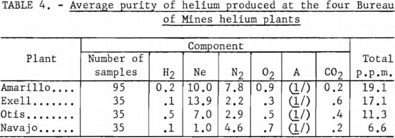
Over 200 analyses were made of helium contained in conventional cylinders, obtained from the Amarillo, Exell, Otis, and Navajo Helium Plants, during the 6-month period ending March 1, 1959. Total impurity concentrations, in parts per million, were as follows: Amarillo, 19.1; Exell, 17.1; Otis, 11.3; and Navajo, 6.6. Neon and nitrogen were the major impurities. Complete data are shown in table 4 in the body of this report.
Introduction
Increasing demand for helium containing less than 50 p.p.m. total impurities for missile and atomic energy applications requires reliable determination of the trace impurities in Grade-A helium. For these applications, it is necessary that the impurities be identified and their concentrations known within a tolerance of 1 p.p.m.
Mass spectrometer thermal conductivity, and catalytic conversion methods have thus far been used for determining trace impurities in helium. These methods are, however, inadequate for various reasons. The mass spectrometer, such as Consolidated Electrodynamics Corp. 21-103, is limited in sensitivity, for most contaminants, to about 25 p.p.m. Instruments based on the thermal conductivity method, such as those manufactured by Gow-Mac Instrument Co., Beckman Instruments, and others, are satisfactory for monitoring nitrogen and hydrogen in helium, but since these gases have opposite thermal conductivity effects, this method, when used alone, gives indefinite results.
Catalytic conversion methods, such as are employed in an instrument manufactured by Baker & Co. for analysis of trace quantities of hydrogen and oxygen, are not responsive to other impurities and are therefore poorly adapted to an overall analysis of trace impurities in helium.
Recently, methods employing gas chromatography have been utilized in this problem. This technique, however, is unsatisfactory, because neon, a major contaminant in Grade-A helium, cannot be quantitatively measured.
A method of repurifying helium by adsorbing impurities into better metals at high temperatures is being used by at least one industry. This method has been extended to the determination of trace impurities in Grade-A helium.
Total impurity concentrations around 200 p.p.m. can be estimated by observing the quality of aluminum welds prepared by the heliarc method, using the helium to be analyzed as feed to the arc. This method is inadequate because it is not quantitative, does not identify specific impurities, and will not show the presence of neon and argon in Grade-A helium. The Helium Activity and industries consuming helium require an instrument that will meet this need. The method described herein was suggested by the third author. It was tried and perfected in the Bureau of Mines Helium Activity Research Laboratory at Amarillo, Tex. The apparatus is described in detail in this report.
Apparatus and Experimental Procedure
Description of Apparatus
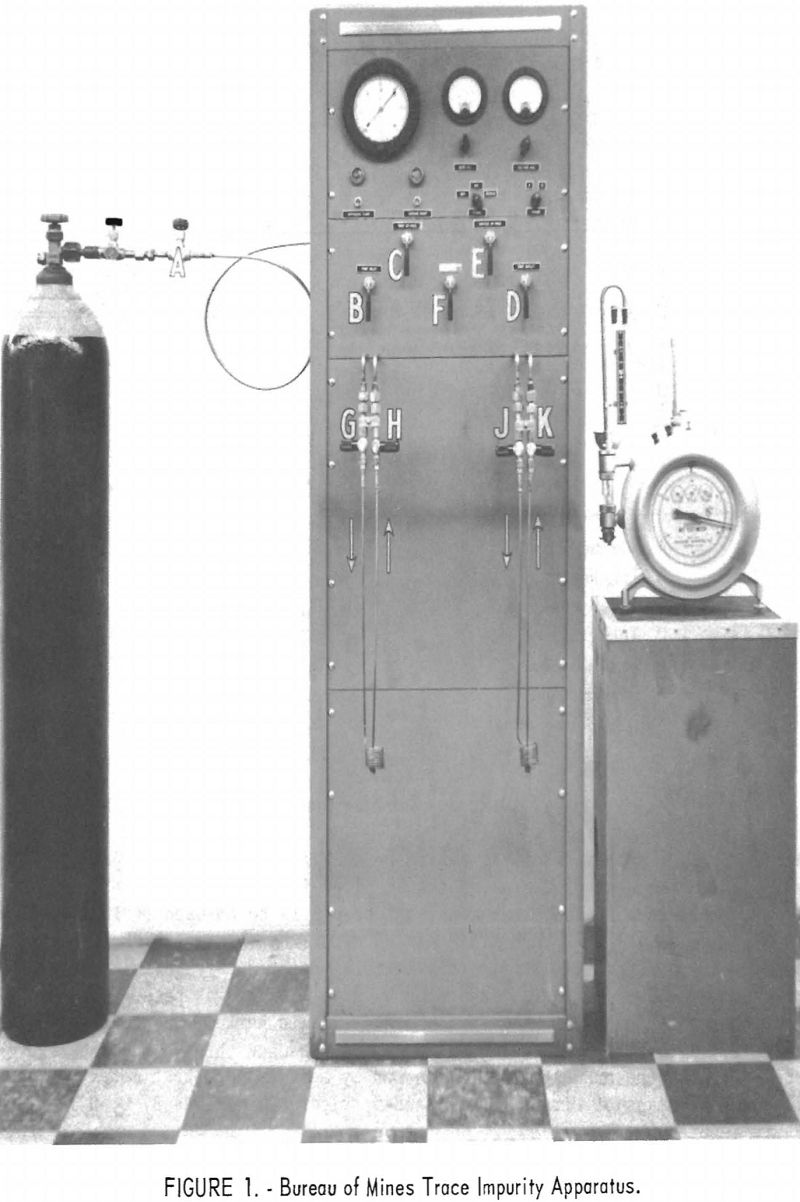
Figure 1 is a front view of the completed apparatus, showing a gas cylinder attached. The apparatus is essentially self-contained, requiring only a 110-volt a.c. power source, a source of cooling water, a supply of liquid helium, and an external wet-test meter. It incorporates vacuum equipment, two Pirani gages for measurement of vacuum, two coil-and-trap assemblies to contain the impurities, and a fixed orifice for controlling flow in the apparatus. Stainless steel tubing is used wherever possible, and all stainless steel connections are silver-brazed. The apparatus is assembled in a relay-rack cabinet with overall dimensions of 17 by 22 by 67 inches.
A gas flow diagram is given in figure 2. Before entering the sample into the apparatus, both traps are attached and the entire system is evacuated by means of forepump 8 and oil-diffusion pump 7, with liquid nitrogen around trap 6, valve A closed, and all other valves open. Following
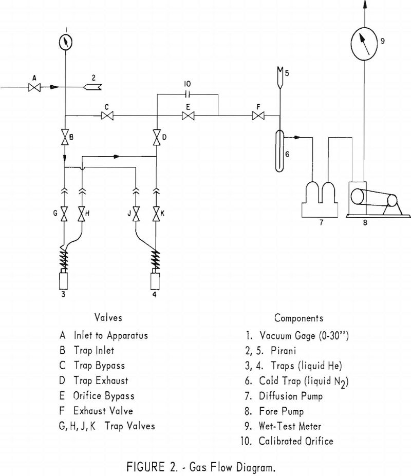
evacuation, a small flow of the gas to be analyzed is allowed to pass through valve A and the rest of the apparatus to purge it of residual gases. Only one trap is used in each run. Assuming that trap 3 is to be used (valves G and H open), then valves E, J, and K are closed after the system is purged and again evacuated. Gas from the sample container is admitted through valve A, and the pressure in the apparatus is indicated by gage 1. The gas passes through valve B into trap 3, which is surrounded by liquid helium, thence through valve D, calibrated orifice 10, valve F, and exhausts through the vacuum system. Flow of the exhaust gas is measured by means of wet-test meter 9. Vacuum is noted by means of Pirani gages 2 and 5, figure 2. Valves B, C, D, E, and F are V-point needle valves.
Liquid-Helium Trap
Figure 3 is a detail drawing of the freezeout coil and trap assembly. The coil is wound to a diameter of approximately 1.5 inches, using seven turns of 0.093-inch-outside-diameter (OD) stainless steel tubing having a wall
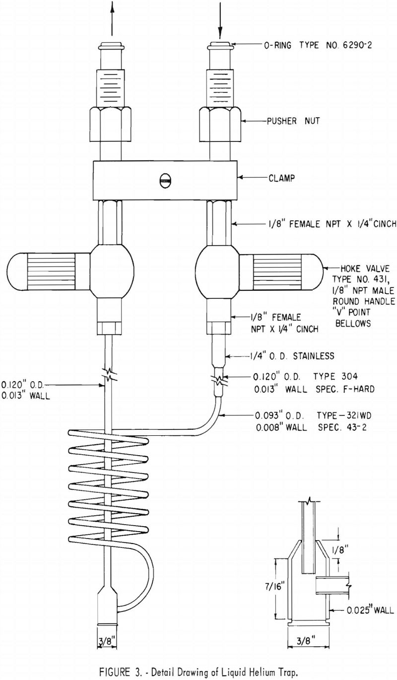
thickness of 0.008 inch. The coil terminates in a trap machined from 3/8-inch stainless steel rod. The trap consists of a “body” and a “cap”, as shown in the inset in figure 3. The cap is silver-brazed to the body. This trap serves as a reservoir for the solids formed in the coil. The volume of the coil-and-trap assembly is slightly less than 10 cm³. Liquid-helium requirements are kept low by making the cooled portion small and using material of low thermal conductivity. The two legs of the coil-trap assembly are 0.120-inch OD 304 stainless steel tubing having 0.013-inch wall thickness. Bellows valves, with V-point, are employed in the trap assembly. Use of two traps permits impurity concentrations of duplicate samples from each cylinder at a faster rate than would be otherwise possible. To prepare a large number of concentrated samples, it is helpful to have additional coil and trap assemblies. In this laboratory 12 of these assemblies are used.
Operation of Apparatus
In high-vacuum apparatus it is essential that the inner walls be kept clean and free of moisture and high vapor-pressure contaminants. If adsorption occurs on inner surfaces in the apparatus, it is difficult to determine in ensuing runs whether the impurities are contained in the inlet gas or are due to outgassing of adsorbed contaminants. For this reason, organic solvents should never be used in cleaning the apparatus. The technique of repeatedly evacuating the apparatus, then purging with helium while the traps are heated gently, is used to remove impurities. When not in use, the apparatus is kept filled to atmospheric pressure with dry helium.
In placing the apparatus in service, the freezeout traps are disconnected, valves A, B, and D (fig. 2) are closed; valves C, E, and F are opened; and the system is evacuated. When gage 1 indicates a vacuum of the same magnitude as the local barometric pressure, Pirani gages 2 and 5 are turned on and read on the millimeter scales. Liquid nitrogen is placed around cold trap 6, and the Pirani gages are then switched to the micron scales. When the pressure is below 1 micron, a check for leaks is made by closing valve F and observing Pirani 2 for pressure increase. If none occurs, the system is considered operable. Valve F is next opened, and the freezeout trap assemblies are attached, making sure that the coil side of each trap is connected to the trap inlet line. Valves B and D and trap valves G, H, J, and K are opened; the system is evacuated to 1 micron; and a second check for leaks is made following the same procedure.
A cylinder of the helium to be analyzed must be connected to the inlet of the apparatus through a special adapter valve attached to the cylinder. This is a “needle nose” valve and is much better for regulation of flow than the cylinder valve itself. This special valve is shown in figure 1 between the cylinder valve and valve A. It should be purged by opening it slightly and then fully opening the cylinder valve. The adapter valve is then closed and the cylinder is connected to the inlet of the apparatus. The Pirani gages are turned off. Valve A is opened and the system evacuated, then the cylinder adapter valve is opened slightly to allow a slow purge of helium through the system. Care should be taken that the pressure in the system does not rise more than a few inches above atmospheric pressure, as otherwise the standard taper joints housing the Pirani elements may be blown off. After purging the system for approximately 5 minutes, inlet valve A is closed and the cylinder adapter valve opened.
Valve C is next closed, and A is opened slightly to allow a slow flow through the traps. To hasten evacuation of the system, the traps may be heated slightly with a gas flame. Next, inlet valve A is closed and C is opened. The Pirani gages are turned on and the system is evacuated to below 1 micron. Then valves C and E are closed. The valves on the trap in use should be open, those on the other trap closed.
To conserve liquid helium, the trap in service is precooled with liquid nitrogen and then is surrounded with a dewar flask containing liquid helium. Readings of the wet-test meter and barometer are noted, and valve A is opened slightly to enter a flow of sample gas through the trap. Gage 1 (fig. 2) should indicate about 10 inches vacuum. If the pressure is much higher than this, erratic flow occurs. If a constant pressure is maintained at this point, the flow will be constant through the fixed orifice. The Pirani gages may be turned off during the gas flow.
After one quarter to one half cubic foot of gas has passed through the system, as shown by the wet-test meter, inlet valve A is closed. It should take approximately 8 minutes to pass the sample through the apparatus. Faster flow rates may result in incomplete freezeout of impurities.
After the sample has passed through the apparatus, Pirani 2 is turned on and the system is evacuated to 1.0 mm. Then valve E is opened and the system is pumped down to less than 0.1 mm. pressure. Valve C is next opened to allow a complete pumpout of the helium from the trap and lines up to valve A.
After the pressure falls to 1.0 micron or less, both trap valves are closed, and the volume of helium passed through the trap is read on the wet-test meter. The trap is then warmed to room temperature for analysis of the sample by the mass spectrometer.
Sufficient time (at least 30 minutes) must be allowed for the gas to warm and become uniformly mixed before analyzing it. The pressure in the trap is measured when the sample is entered into the mass spectrometer. At this laboratory a Consolidated Electrodynamics 21-103 instrument is employed.
Calculations
The volume of each trap assembly must be known before making a run. This is determined by comparison with a known volume, previously calibrated. The pressure of the vaporized impurities and helium contained in the trap is determined by means of a calibrated micromanometer located on the mass spectrometer. By introducing known pressures in each trap assembly and then attaching the trap to the mass spectrometer inlet, a reading on the micromanometer is obtained. From a plot of these data, the pressure existing in the trap after a run is determined from the micromanometer reading obtained when the sample impurities are entered into the mass spectrometer for analysis. The mole-percent of each component in the concentrated impurity sample is calculated from the mass spectrometer data.
The calculation of the trace impurity percentage is dependent upon the degree of concentration (concentration ratio) occurring during each run. Assuming the temperature to be constant, this ratio can be determined by measurements of volume and pressure.
A material balance may be written as follows:
PV = PtVt + PHeVHe…………………………………………………….(1)
in which P = the pressure of the sample of Grade-A helium,
V = the total volume of Grade-A helium entered into the apparatus,
Pt = trap pressure,
Vt = trap volume,
PHe = pressure of purified helium leaving the apparatus (equal to barometric pressure at time of run), and
VHe = volume of purified helium leaving the apparatus (measured by wet-test meter, with appropriate corrections).
The traps contain a fraction of residual helium (designated Het) in addition to the impurities; thus, we may write:
PtVt = PiVi + PtVtHet…………………………………………………..(2)
where Pi = pressure of concentrated impurities contained in the trap, and
Vi = volume of concentrated impurities in the trap.
Substituting equation (2) into (1) we obtain
PV = PiVi + PtVtHet + PHeVHe……………………………………(3)
In the experimental method Pt, Vt, PHe, VHe directly measured. The concentration factor is equal to PV, the product for the total sample of Grade-A helium passed through the apparatus, divided by PiVi, thus:
Concentration Factor = PV/PiVi………………………………….(4)
Solving (2) for PiVi and substituting into equations (3) and (4), and substituting PV from equation (3) into (4) we obtain

Total impurity (p.p.m.) = 10 6/C.F…………………………………………..(6)
Substituting equation (5) into (6),
Total impurity (p.p.m.) = 10 6 [PtVt – PtVtHet/PtVt + PHeVHe]……………(7)
Because, in actual practice, PHeVHe>>PtVt equation (7) may be simplified to:
Total impurity, (p.p.m.) = 10 6 [PtVt – PtVtHet/PHeVHe]………………………..(8)
Experimental Data
A typical run gives the following data:
Run 3161
Pt = 19.03 mm. Hg. Vt = 9.34 cm.³
Het = .017
PHe = 670.2 mm. Hg.
VHe = .502 ft.³
These data are substituted in equation (8) to give:
Total impurity, p.p.m. = 10 6 [(19.03) (9.34) – (19.03) (9.34) (.017)/(670.2) (.502) (28316)] = 18.3
This is the total impurity content, independent of the individual contaminants.
Table 1 gives the results of mass spectrometer analysis of the concentrated impurity sample, less the residual helium (1.7 percent) contained in the trap.

Percentage of each contaminant in the concentrated impurity sample is multiplied by the total parts per million to give the parts per million concentration of each component in the original helium sample. These data, for the above example, are given in table 2.

Table 3 gives data obtained in several runs made using a single cylinder of helium to determine the reproducibility of the method.
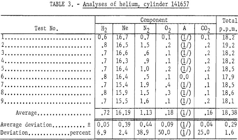
The relatively high percent deviations obtained for nitrogen, oxygen, and carbon dioxide (38.9, 50.0 and 25.0 percent, respectively) result from the low absolute values obtained and the method employed in rounding off the data. Oxygen and carbon dioxide are minor contaminants (0.18 and 0.16 p.p.m., respectively). The percent deviation obtained for neon, the major impurity, was only 2.4, and that for the total impurity content was 1.6.
During the 6-month period ending March 1, 1959, 200 samples of Grade-A helium produced at four Bureau of Mines plants were analyzed. All samples were contained in conventional compressed gas cylinders. The average of all data obtained in these analyses are given in table 4.
Reproducibility of data contained in this table is equal to, or better than, the data given in table 3. It is noted that the total impurity content varied from approximately 11 to 20 p.p.m. at the. Amarillo, Exell, and Otis plants, of which more than half was due to neon. The Navajo plant produces the purest helium of any of the four plants, the total impurity content averaging 6.6 p.p.m.
During the development of the apparatus described in this report, several experiments in which two traps were connected in series established the fact that all impurities were isolated in the first trap, provided that the desired flow rate (0.5 cu. ft. in 8 minutes) was not exceeded.
The apparatus requires only a modest supply of liquid helium. Approximately six concentrated samples can be obtained per liter of liquid helium.
It is hoped that this method will be helpful in evaluating performance of helium repurification equipment in connection with wind tunnel, reactor cooling, and missile-testing applications.
