The continuous vacuum filtration is the solid-liquid separation process that is nowadays most frequently used in the beneficiation industry all over the world.
After a development time of several decades, the various filter types such as drum filter, disk filter, plate filter and belt filter can be considered as a sound fractional design ensuring a trouble-free operation.
Nevertheless, the vacuum filtration does no longer meet the present and future technological requirements. The moisture content of filter cakes is too high. Their thermal secondary drying is too expensive (coal, ores) and may bring about undesirable material changes and the filter cake conditioning with water-binding substances for dumping purposes is too costly.
The possible throughput increase is not only limited by the pressure difference for vacuum operation but also by the cake thickness diminishing with rising speed. Under a minimum thickness, the cake can no longer be removed from the cloth.
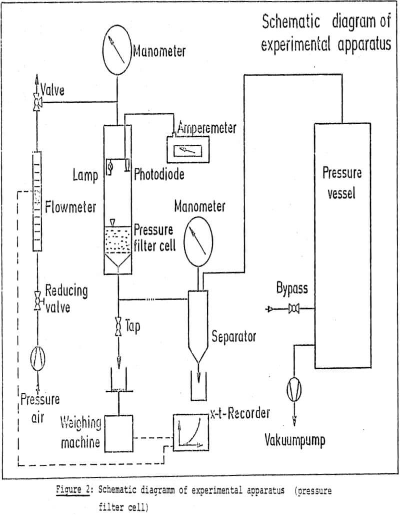
The moment of transition from cake formation to dewatering of filter cake is ascertained by utilization of the different reflection behaviour of liquid and cake by means of a combination of lamp, photo-diode and amperemeter.
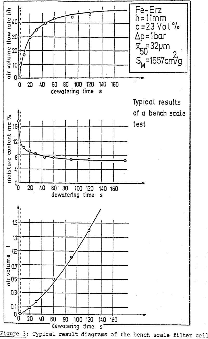
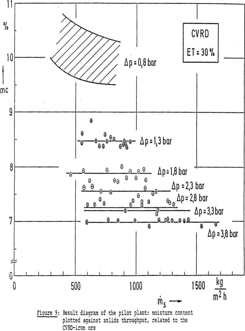
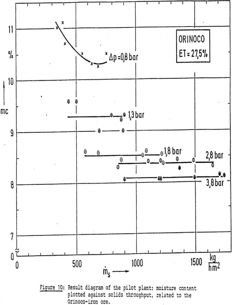
The reexamination with several ore types and the conversion by calculation to the rotation of a vacuum-type drum filter showed that during vacuum filtration Δp=0.8 bar) particularly in the case of very fine iron ore types, a pressure increase by 1 bar in the form of overpressure yielded the optimum results.
This idea of hyperbar vacuum filtration i.e. vacuum filtration with additional, mean, overpressure on the filter cake and suspension, has also particular advantages with regard to equipment:
- special pressure filter constructions are needed but all available sound filters can be further used by installing then in a correspondingly pressurized room.
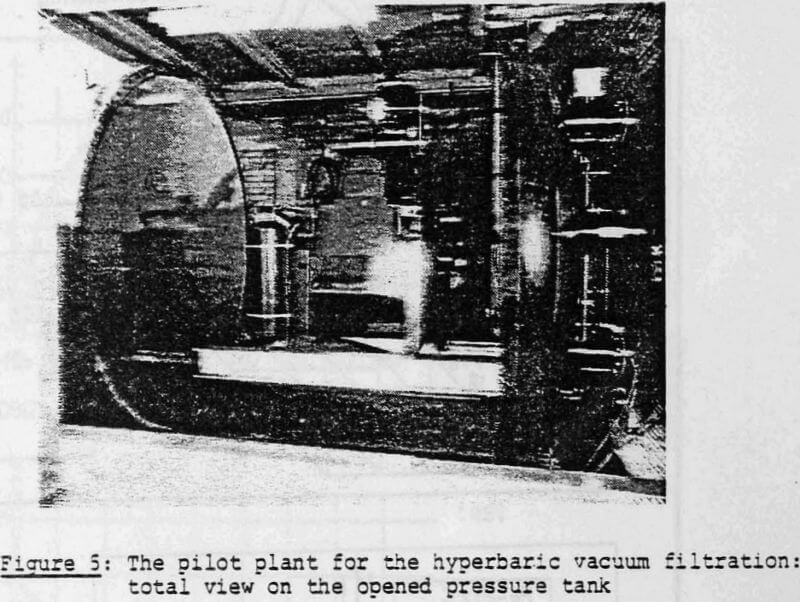
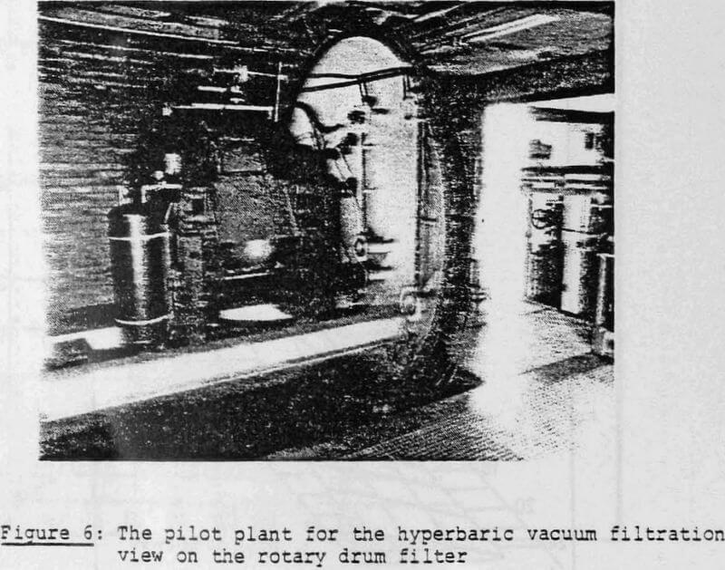
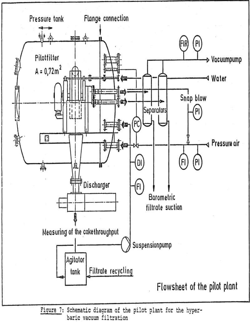
- The problems of a gas-tight discharge of filter cake from the pressurized room are much less difficult at overpressures of up to 1 or 1.5 bar than for pure pressure filter designs operating at an overpressure of 4-6 bar. On the basis of the results obtained with the laboratory-type filter and in the light of these considerations, a pilot plant was designed in which a commercial vacuum drum-type filter of 0.7 m² filter area was installed in a pressurized room.
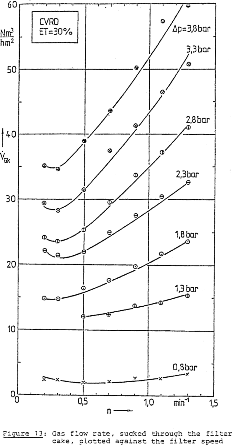
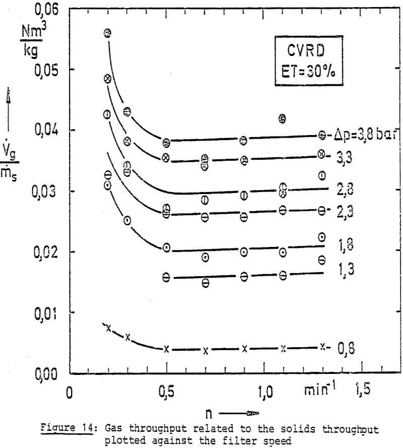
The air leaving the filter escapes through the filtrate piping system and separators. On this occasion, the air passing through the filter cake is measured and after pressure and temperature correction indicated, in standard volumes.
In the case of a pure pressure filtration, the compressed air is adjusted to the desired filtration pressure, in the case of a pure vacuum filtration the underpressure is produced by a water ring pump and applied through the separators to the filter. In the event of the hyperbar vacuum filtration, the over and underpressure are simultaneously applied.
The plant was installed in the bay of the Institute for Mechanical Process Technology and Mechanics and has been in operation since one year.
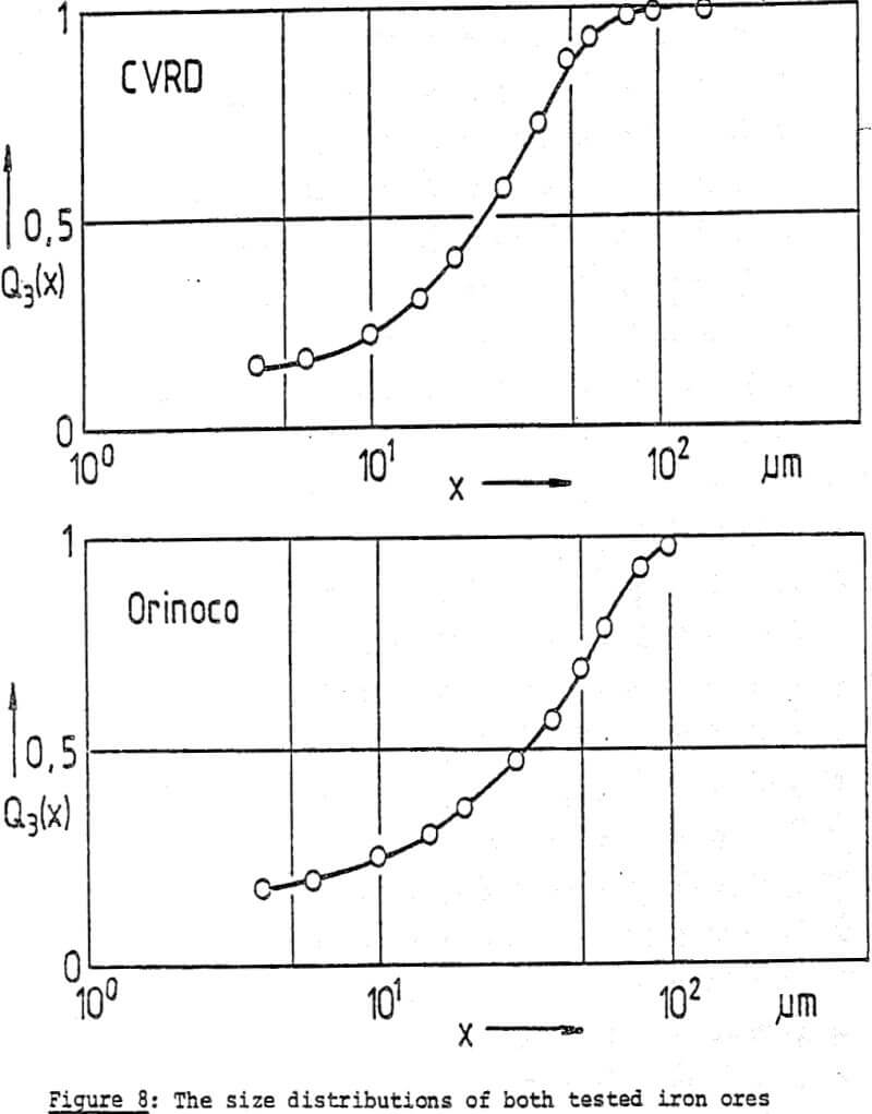
Up to now, two ores were available (the brasilian, hematite CVRD iron ore and the Venezuelan limonitic hematite Orinoco-iron ore which ware ground to very fine grain sizes in tests and which in this size distribution are not produced in plants in operation.
The size distributions are indicated in Figure 8.
The remarkable values are the following:
CVRD ore:
100% < 120 um/50% < 27 µm/10%,< 10 µm
Specific surface SM = 1890 cm²/g
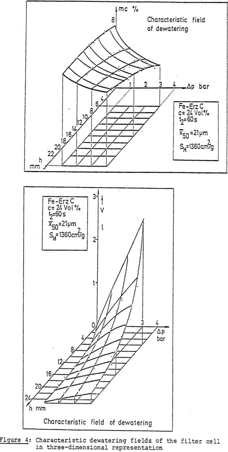
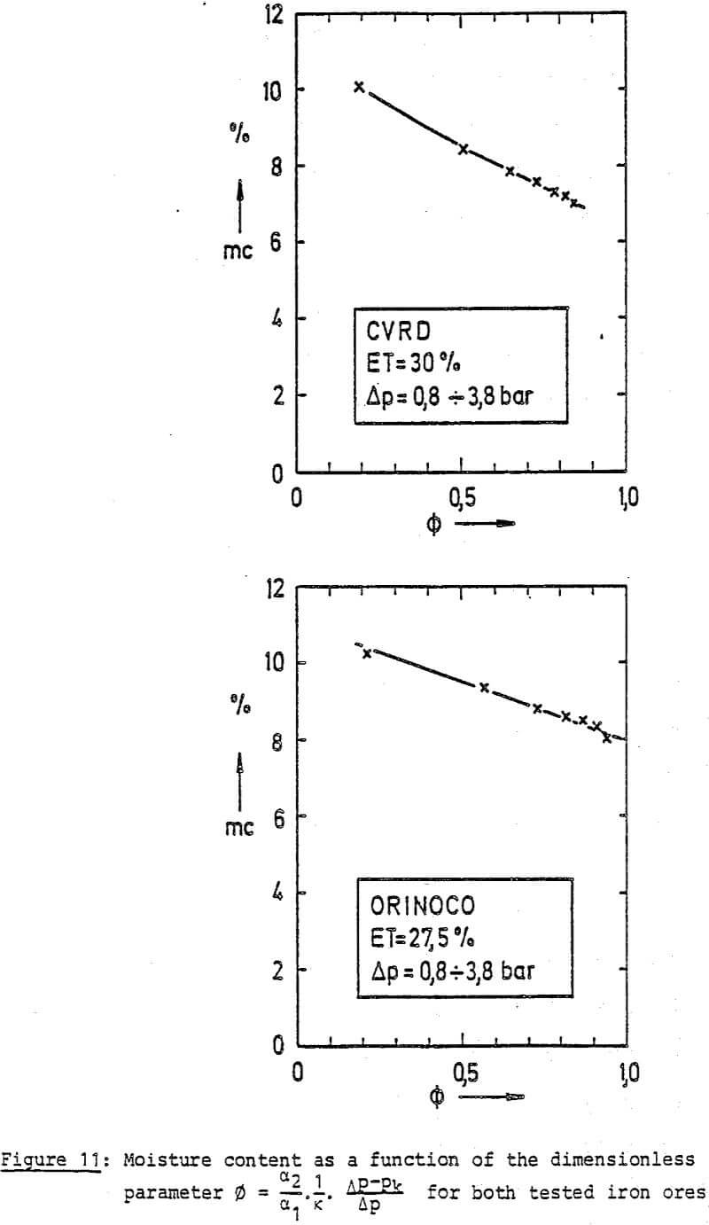
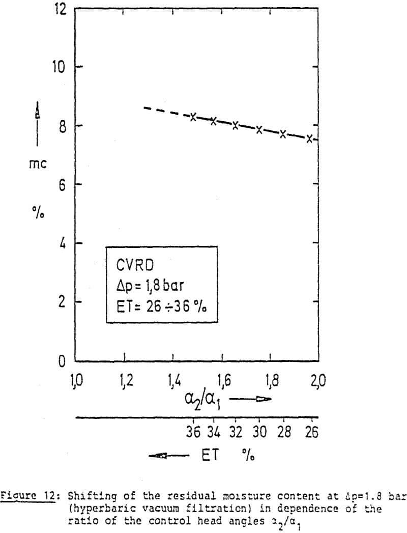
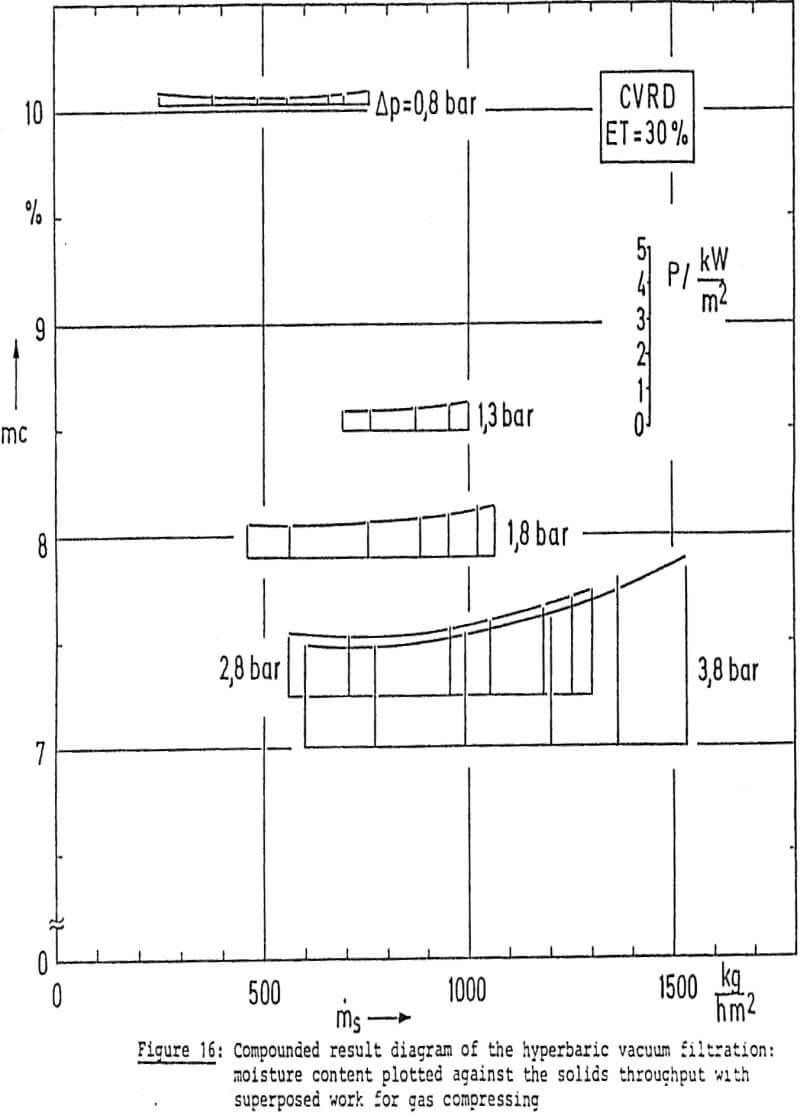
If the residual moisture content results are plotted on this parameter, a typical profile for the product involved is obtained from which the dependence of the residual moisture content on the parameters: pressure difference suspension concentration and control head angle ratio α2/α1 can be seen.
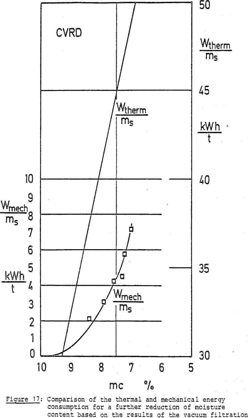
For most beneficiation products whose capillary pressure is between 0.5 and 1 bar, it is already possible by adopting the hyperbar operating method to achieve the same low residual moisture contents which – as was hitherto assumed – could only be attained by pressure filtration at higher pressures. However, this operating method means that as a whole lower overpressure is sufficient which in several advantages result.
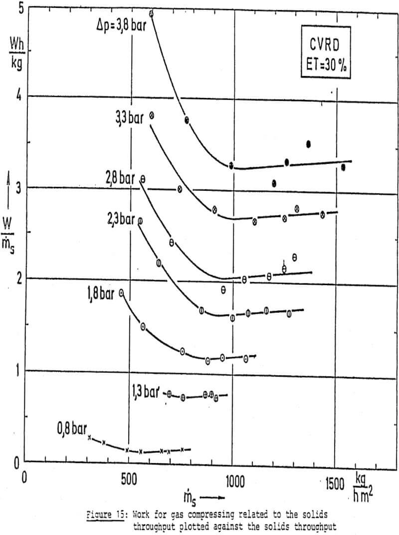
On the other hand it should be noted that due to the application of higher pressure differences higher air flow rates have to be sucked through the filter cake.
In the case of such a small laboratory type filter as it was installed in the pilot plant, the ratio of control head leakage referred to the filter area is of course very unfavourable. It can be assumed that this can be remedied by improving the control head design for hyperbar vacuum fiItration.
Now the question can be answered to which extent it is advisable to use the pressure or hyperbar vacuum filtration to obtain low residual moisture contents.
Moreover, it is possible to have re-course, ir. the case of hyperbar vacuum filtration, to the sound functional design of all conventional vacuum rotary filter designs.
A more detailed cost-efficiency analysis can only be comparatively made for a specific project.
