Table of Contents
In diamond-drill work, a true sample consists of all the material cut by the bit—both core and cuttings. As the recovery of this sample is the object of diamond drilling, the utmost care should be taken to secure it. Speed of drilling and low costs are of little value if an inaccurate sample is obtained. The engineer in charge must study his material and lay out the plan of sampling, and then see that the drill runner follows his instructions; for the runner may be more interested in obtaining a large footage than in developing accurate methods of sampling.
The foregoing is a brief description of a few of the common methods of collecting and preserving diamond-drill samples. Variations of these methods will suggest themselves on every new piece of work. The essential point to bear in mind in all diamond-drill sampling is that the sample must comprise all of the core obtainable and all of the cuttings. This involves the proper operation of the drill as well as the careful collecting of the core and sludge. The engineer must use his own judgment as to the practical methods that will give the desired results under the conditions obtaining.

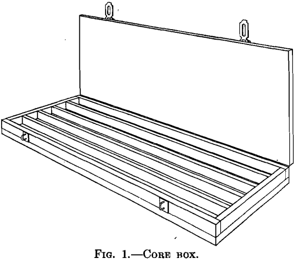
When the core has been removed from the core barrel, it should be placed in a core box in the exact order in which it is taken from the ground. This box, Fig. 1, is usually a shallow tray 4 or 5 ft. (1.2 or 1.5 m.) long, with partitions running lengthwise between which the core fits snugly. It is so designed that, after the cover is fastened in place, the core will retain its position when the box is moved. As the core from each run is placed in the box, a wooden block, upon which the depth of the hole is written, should be placed after the last piece of core. Each run is thus separated and shows the exact depth at which it was made.
If the core is to be used for certain types of inspection, such as foundation testing, a mark on each piece should show which end was uppermost in the hole. This will prevent a piece being placed in the box in the reversed position. Frequent checks of the depth of the hole should be made with a steel tape.
In oil reconnaissance work, where the drill is used to determine the structure by establishing the elevations of certain key horizons, the essential information desired is the exact depth at which certain correlated beds are reached in different drill holes. It is, therefore, especially important to preserve the core in its original position in order to study the various criteria of correlation such as fossil’s, shale partings, color changes, and contacts. It is often desirable to have the runner keep a separate record of the depth of the harder and softer beds, as indicated by the pressure on the drill feed. This will serve as a check against the record given by the core.
Collecting the Sludge
The ideal sample of the material drilled would consist of 100 per cent, core of uniform size, but this ideal is seldom reached. In certain ores, the rich and softer streaks will tend to grind, so an analysis of the core that is left will not give the true grade of the material drilled. In such cases, the cuttings or sludge must also be collected and analyzed. The correct grade of the ore is obtained by analyzing both core and sludge separately and combining the results, as described in Method 3.
In order to obtain a correct sludge sample, all of the water pumped down the rods must be returned, for if any is lost in crevices or in broken and porous rock part of the sample will go with it. To avoid this, the openings in the walls of the hole must be closed by casing, cementing, or other treatment. Care must be taken that the sample is not enriched or impoverished by material caving from the wall of the hole above the bit. If there is any tendency for this to take place, the casing must be kept well down toward the bottom of the hole. There are three methods in common use for collecting the sludge; the one to be adopted depends on the character of the material drilled and the results desired.
Method 1.—When the material shows little tendency toward concentration, the water may be run into a tub and allowed to overflow. Enough cuttings will be retained in the tub to furnish a sample. By this method, however, the sample is usually enriched, for the lighter particles are carried off; this method, therefore, is rarely satisfactory.
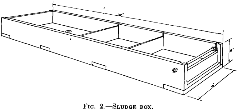
Method 2.—The sludge box (or floor box), Fig. 2, will give much better results. This box is 12 to 18 in. (30 to 45 cm.) wide, 6 to 10 in. (15 to 25 cm.) deep, and 4 to 10 ft. (1.2 to 3 m.) long and contains two or more baffle plates to aid in the settling of the cuttings. The water may run into the box through a tee, or the casing may pass through a properly packed stuffingbox or gland in the bottom of the box. Samples may be removed at any time that the rods have to be pulled, but preferably at 5 or 10-ft. intervals. In any case, care should be taken that core and cuttings represent the same interval in the hole. At the end of each interval, the drill is stopped and water pumped through the rods until

the hole is clear of all cuttings and the return water clean. After the cuttings have settled in the sludge box, the top water is carefully siphoned or poured off, leaving the residue in the bottom. This is dried  and quartered to convenient size for analysis or assaying, a representative sample being permanently, preserved. This is the method most commonly used when diamond-drilling iron ore. In most ores, there may be considerable concentration of the heavier minerals, especially if the metallic content is small or if there is a great difference in specific gravity between the ore minerals and waste. The sludge box should be used only with due regard to its limitations.
Method 3.—In the third method, which is the most reliable, the return, water is run into three or more barrels through a pipe or launder. When one barrel is filled, the pipe is swung to the next barrel, and so on. After the material in the first barrel has settled sufficiently so that the clear water can be siphoned off, the barrel is again filled. The process is continued until the end of the interval to be sampled. All of the material is then poured into one barrel and allowed to settle further. After all of the clear water has been drained off, the residue is removed, slowly dried over a fire, quartered, and sacked. The number of barrels used depends on the time necessary for the material in suspension to settle. When this method is used, the hole must be in such condition that all of the cuttings are washed to the surface. On one of the large copper deposits in Arizona, this method gave remarkably accurate results even though less than 50 per cent, of the core was recovered. Later test pits and mining operations checked the drill sampling within 0.005 per cent, in carbonate ore and 0.05 per cent, in sulfide ore. A bit recovering a 1 1/8-in. core was used. The choice of sampling methods must depend on the engineer’s judgment of the character of the material to be sampled. In case of doubt, it is better to err on the side of accuracy than to risk getting a worthless sample.
Averaging Core and Sludge Analyses
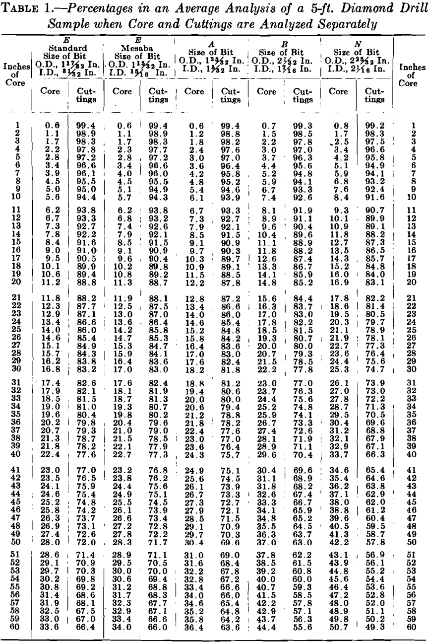
To obtain the average analysis of the material drilled in a given run, the separate analyses of both core and sludge (cuttings) must be combined in the proportion of their respective masses, as originally lying in the ground. Fig. 3 represents a 5-ft. run with an “N” bit, in which only half of the core was recovered. The cuttings represent all that part of the hole which is not core but it would not be correct to take the arithmetical mean of the two samples because, as the illustration shows, the cuttings are the largest part of the sample and must be weighted accordingly. In this case, the core is only 25.3 per cent, of the total sample, and the cuttings are 74.7 per cent. If the analysis of the core is multiplied by 25.3 and added to the analyses of the cuttings multiplied by 74.7 and the sum divided by 100, the result will be the average analysis.
Table 1 has been prepared to facilitate the calculation of average analyses; the figures are based on the ratios of the volume of core and the volume of cuttings to the total volume of the hole. The values of the separate analyses made for core and cuttings in a 5-ft. run should be multiplied by the percentage found in the column headed by the size of the bit used, opposite the number of inches of core recovered. The results are to be added and divided by 100 for the average analysis for that run.
Assume that in a 5-ft. run with an “ A ” bit, 34 in. of core are recovered and that the analysis of the core is 57.6 per cent, iron and of the cuttings, 61.0 per cent. Opposite 34 in the column of Table 1 headed Inches
of Core, in column A, appear the values 20.6 and 79.4, which are the percentages of core and cuttings of the total material cut in the hole.
Then,
57.6 x 20.6 + 61.0 x 79.4/100 = 60.3 per cent.
Although this table is made for a 60-in. run, it is a simple problem of proportion to adapt it to a run of any other length. For instance, if a 38-in. run is made and 23 in. of core are recovered, multiply 23 by 60 and divided by 38, which will give a value 36, which for the purpose of the table is to be used as the number of inches recovered.
The table is accurate only in case: (1) the bit is of the dimensions specified at the head of the columns, (2) the hole is of uniform size with no increase, in diameter in the softer strata, (3) there are no additions from caving in the upper portions of the hole, and (4) all of the cuttings are recovered. If a portion of the cuttings is lost or other material is added, the sample will be correct only to the extent that the material analyzed represents a true sample of the actual cuttings. Hence the necessity for extreme care in recovering and sampling the sludge.
Splitting the Core
It is often desirable to retain, a complete core sample to show structure or banding and at the same time have, a portion of the core analyzed, especially where the results of exploration are to be submitted to a prospective purchaser. In such cases the core may be split longitudinally by a, core splitter; it is then possible to grind up one-half into a pulp for analysis while the other half is preserved in its original state.
Permanent Filing of Samples
The method adopted for permanently filing samples depends on the needs of the company doing the drilling. Sludge may be preserved in sacks and the core in the boxes shown in Fig. 1. Some companies find it more convenient to keep the cores in drawers with partitions similar to those in the box; the core is then accessible for future study. In the

Lake Superior iron districts, nearly all the mining and exploration companies have filed both core and sludge in tin boxes 12 by 1½ by 1 in. (30.5 by 3.8 by 2.6 cm.) with hinged cover. In the ore, the core recovery is small. Half the split core, or often a few representative pieces, are placed in the tin box with a sample of the sludge and the end of the box is properly labeled. A representative sample of the hard rock above the ore is kept also in the tin box. By this method samples can be stored in a relatively small space.
