Lead is one of the oldest metals known to man and has been used for hundreds of years. The method for producing lead from galena has changed very little. A lead concentrate is mixed with fluxing agents, roasted to remove sulfur, and heated to about 1,000° C with carbon to obtain an impure metallic product, which is refined. The smelting process is a low-cost operation but results in SO2 and lead emissions.
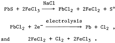
The Bureau of Mines under a cost-sharing program with St. Joe Minerals Corp., ASARCO, COMINCO, Ltd., and AMAX has investigated an alternative method for producing lead. The method consists of leaching galena concentrate with a ferric chloride-sodium chloride solution to make lead chloride. The lead chloride is electrolyzed in a molten-salt bath to produce lead metal and chlorine. The chlorine is used to regenerate ferric chloride in the leaching solution. The reactions involved are:

The low melting point (327° C), of lead, its high electrochemical equivalent, and the availability of stable low- melting electrolytes make the development of a molten-salt electrolytic process possible. Lead chloride is a favorable starting material because it is not hygroscopic and has good electrical conductivity when molten. Purified lead chloride can be electrolyzed to market-grade lead without a refining step.
Molten-salt electrolytic methods for producing lead metal have been studied but have not attained commercial acceptance. The leaching and electrolysis procedures have been described in Bureau of Mines publications. Since the impurity compounds in the lead chloride could influence the lead product quality and power consumption in the electrolysis step, research was performed to determine the effects of Zn²+, Ca²+, Na+, Mg²+, Fe²+, Cu²+, SO4²-, and H2O on electrolysis. Impurity effects were evaluated in the concentration range in which significant problems with cell voltage, current efficiency, sludge formation, and viscosity were observed in the earlier pilot demonstration unit (PDU).
Equipment and Materials
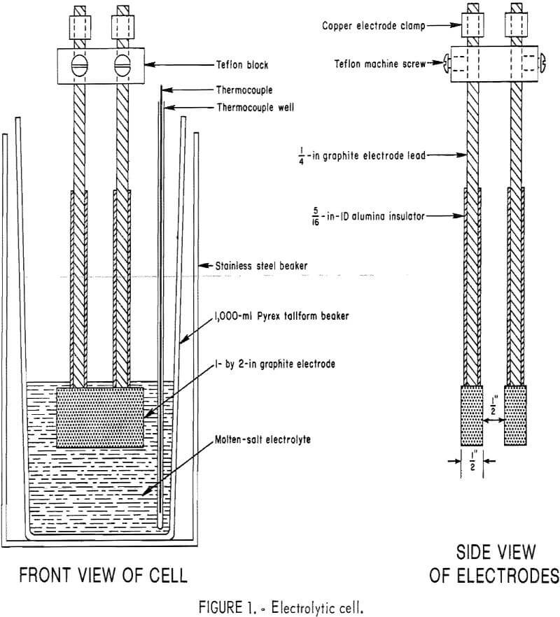
Figure 1 shows the electrolytic cell. The electrolyte container, a 1,000-ml Pyrex tallform beaker, had a capacity of about 1,000 g of electrolyte. Electrodes were made of high-purity graphite. Electrode leads were ¼-in diameter graphite sheathed with alumina tubes.
A pot furnace with heating elements 5 in high was used to heat the electrolytic cell. The furnace was controlled by an autoproportioning, offset correction controller. A protective stainless steel beaker, 4.5 in in diameter by 7 in high, was placed inside the furnace to keep the molten salts from damaging the heating elements. Temperature was measured with an electronic pyrometer, which had an open thermocouple interrupter and automatic cold junction compensation. The Chromel-Alumel thermocouple for the pyrometer was stainless steel sheathed and placed inside a Vycor thermocouple well.

A Hewlett Packard model 6264B constant-current silicon rectifier was the direct current source. With this rectifier, the current was constant to ±0.03 pct in the range of operation. Cell voltage was measured with a solid state electronic digital voltmeter. Amperage was measured with a precision dc ammeter across a 25-amp, 50-mv inline shunt.
Anhydrous MgCl2, FeCl2, and PbSO4 were ultrapure grade, and all other chemicals were reagent grade.
Experimental Procedure
The electrolyte composition for all experiments was 63.3 pct PbCl2, 24.5 pct KCl, and 12.2 pct LiCl. The composition was similar to that used in the PDU. All salts were dried for 24 hr at 110° C with the exception of the moist PbCl2 used in some tests.
Electrolyte components were weighed, mixed, heated in air until molten, stirred, allowed to come to thermal equilibrium, and then sampled. Sampling was done prior to electrolysis by dipping a 10-ml ladle into the molten solution and pouring the molten salt into a graphite mold to cool. The sample was placed in a heated bottle and capped. Samples were ground to minus 40 mesh in a warm mortar, which minimized moisture contamination. The lead metal samples were obtained by drilling two holes in the lead metal and cutting the drilled material into small pieces. Analyses for cations were made with an inductively coupled plasma emission spectrometer. Analyses of Cl- and SO4= were performed gravimetrically.
Between tests, the electrodes and electrolytes were stored in a drying oven at 110° C to prevent moisture adsorption. Solid electrolytes in tallform beakers were taken from the drying oven and placed in the furnace. After the electrolyte was heated to about 450° C, the electrodes were placed in the molten electrolyte, and the system was permitted to attain thermal equilibrium before the experiments were started.
Each experiment was performed for 4 hr and controlled at 5 amp. Anode and cathode current density was 2.5 amp/in². Average voltage was obtained after exclusion of the initial reading. The experiments were terminated by withdrawing the electrodes from the molten electrolyte and permitting the molten salt to drain from them. The warm electrodes were placed in a drying oven at 110° C.
After removal of the electrodes, the beaker was removed from the furnace and its contents of molten lead and salt were poured into a graphite crucible. After cooling for 30 min the solid materials were removed from the crucible. The salt was broken into chunks and reused in the next experiment. Salts adhering to the lead button were removed by leaching in a hot ammonium acetate-hydrochloric acid solution. The metal button was weighed, and the current efficiency was calculated. From the current efficiency, the amount of PbCl2 needed for the next experiment was calculated. The determined amount of PbCl2 was weighed and added to the salt chunks, and the next experiment was started. After each series of tests on an impurity, the electrodes were leached in a 10-pct-HCl solution to remove adhering salts and dried before reuse.
Results and Discussion
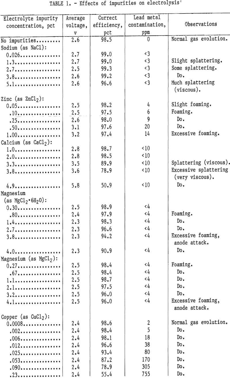
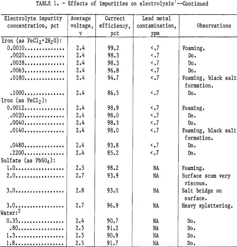
The results of adding the impurities to the PbCl2-KCl-LiCl electrolyte in lead electrowinning are presented in table 1.
Previous Bureau research showed that the lead chloride concentration can be varied considerably and not affect the melting point, voltage, or current efficiency. A 5-pct variance in potassium and a 0.4-pct variance in lithium had very little effect on the melting point, voltage, or current efficiency.
A series of 15 experiments using reagent-grade LiCl, KCl, and PbCl2 at 450° C was made to obtain baseline data for comparison with data presented in this report. Average cell voltage was 2.6 v, and average current efficiency was 98.5 pct. Low electrolyte viscosity permitted the chloride to escape easily.
Adding sodium to the electrolyte resulted in a very small decrease in current efficiency and no change in voltage. The current efficiency was 99 pct between 0 and 3.8 pct Na and decreased to 97 pct at 5 pct Na, When the NaCl was increased, the electrolyte became more viscous, which caused electrolyte splattering. Analysis for sodium showed 2 to 3 ppm in the lead products.
Adding zinc to the electrolyte decreased the current efficiency from 98 to 97 pct. When the zinc concentration was increased to 1 pct, the voltage increased from 2,6 to 3.2 v. At 1 pct Zn, the electrolyte foamed excessively. When zinc concentration increased in the electrolyte, the zinc concentration in the lead metal increased slightly. American Society for Testing and Materials standards for corroding-grade lead metal are <15 ppm Cu <20 ppm Fe, and <15 ppm Zn. No values are listed for Ca and Na.


Calcium was one of the most deleterious impurities and had a large effect on voltage and current efficiency. The voltage increased from 2.6 to 5.8 v, and the current efficiency decreased from 99 to 51 pct when the calcium concentration was increased from 0 to 5 pct. Above 3.8 pct Ca excessive electrolyte splattering was caused by the increase in electrolyte viscosity. The calcium content of the lead metal was less than the analytical detection limit.
Magnesium was added to the electrolyte as anhydrous MgCl2 and MgCl2·6H2O. The hydrated form decreased the current efficiency, decreased the voltage, and attacked the graphite anode. When the magnesium was increased to 4 pct, the current efficiency decreased to 91 pct, and the voltage decreased from 2.6 to 2.3 v. The anhydrous form decreased the current efficiency to 96 pct, but the voltage remained constant at 2.5 v. Both forms of MgCl2 caused corrosion of the graphite anode, but the hydrated form was more corrosive. Both species caused excessive foaming of the electrolyte, but neither contaminated the lead metal.
Copper additions to the electrolyte caused a large decrease in current efficiency. Increasing the copper concentration from 0.0008 to 0.23 pct decreased the current efficiency from 98.6 to 55 pct and increased the copper content of the lead metal to 755 ppm. The decrease in current efficiency and the increase in copper contamination in the lead metal were almost linear with copper additions. Copper additions did not cause a voltage increase, foaming, or an increase in viscosity of the electrolyte.
Iron was added to the electrolyte as anhydrous FeCl2 and FeCl2·2H2O. The iron chloride dihydrate was prepared by mixing FeCl2·4H2O with PbCl2 and heating at 140° C for 24 hr. This was done to simulate the “lead chloride” produced in the pilot plant. The hydrated iron chloride decreased the current efficiency more than the anhydrous iron chloride. When the iron concentration was increased to 0.10 pct by adding FeCl2·2H2O, the current efficiency decreased to 86.5 pct. A black iron oxide sludge deposit formed in the electrolyte. Anhydrous ferrous chloride caused the current efficiency to decrease to 85 pct when the iron concentration was increased to 0.22 pct. The voltage remained constant at 2.4 v when the iron concentration increased. Foaming of the electrolyte was observed at all concentrations during electrowinning.
Sulfate ion was added to the electrolyte in the form of PbSO4 and Na2SO4. When the sulfate concentration increased from 1 to 3 pct the current efficiency decreased from 98 to 93 pct and the voltage increased from 2.5 to 2.8 v. A salt crust formed on the surface of the electrolyte when the sulfate increased to >2 pct because the sulfate solubility in the chloride melt was exceeded. Sodium sulfate added to the electrolyte had the same effect as PbSO4 but to a lesser degree. At 3 pct sulfate, the voltage increased to 2.7 v and the current efficiency decreased to 97 pct.
Using lead chloride with a slight amount of moisture could save energy in drying and minimize dusting problems in handling. Tests were performed to determine the effect of moisture on electrolysis and anode corrosion. Moisture was added with the PbCl2 and caused the current efficiency to decrease to 91 pct when the electrolyte contained 0.35 pct moisture. Current efficiency remained at 91 pct when the moisture was increased. Voltages remained constant. Excessive electrolyte splattering was observed. Moisture added with lead chloride caused incomplete coalescence of the lead metal but no noticeable anode corrosion.
Summary
Significant decreases in current efficiency occurred with additions of Ca²+, Cu²+, Fe²+, PbSO4, and H2O. Slight decreases in current efficiency were observed with Na+, Zn²+, and Mg²+ additions.
The voltage increased from 2.6 to 5.8 v with increasing concentrations of Ca²+. Zinc caused a small increase in voltage. MgCl2·6H2O caused a slight decrease in voltage.
Copper and zinc contaminated the lead metal. Copper in the lead metal increased linearly with increasing copper concentration in the electrolyte.
The graphite anode was attacked by both the anhydrous and hydrated MgCl2. The hydrated MgCl2 did the most damage.
The viscosity of the electrolyte increased with increasing additions of sodium, calcium, and sulfate.
Foaming of the electrolyte occurred with additions of zinc, magnesium, and ferrous chlorides.
The lead metal did not coalesce completely when moist lead chloride was added to the electrolyte, but no anode attack was observed.
