Table of Contents
A rapidly expanding market for Nd-Fe-B permanent magnets has created intense interest in development of a new process for producing neodymium metal. The current industrial process is calciothermic reduction of neodymium fluoride (NdF3), which entails reacting calcium metal with NdF3 at 1,200° to 1,400° C in closed tantalum crucibles. The process was initially developed for yttrium metal production by Daane.
The disadvantages of the calciothermic reduction process are as follows: NdF3 is an expensive form of neodymium; calcium is an expensive reductant; tantalum crucibles are expensive containers that have a limited life; the process requires high temperatures and must be operated on a batch basis; and the neodymium metal produced contains about 1.5 wt pct Ca, which must be distilled to obtain high-purity neodymium.
In recent research, Sharma produced neodymium metal by calcium metal reduction of neodynium oxide (Nd2O3) between 710° and 790° C. The neodymium product was collected in a molten pool of Nd-Fe. The Nd-Fe alloy was removed from the cell and iron and boron were alloyed using an arc furnace to bring the final product to Fe77Nd14B composition, which is used in the rare-earth magnet.
A review of electrolytic production of rare-earth metals from both chloride and fluoride electrolytes was published by Morrice. In the 1930’s, Trombe published a series of papers on electrowinning rare-earth metals from chloride electrolytes. Trombe electrowon neodymium metal from a NdCl3-KCl-CaF2 electrolyte. Subsequently, he deposited neodymium metal at 625° to 675° C into a Mg-Cd alloy, which was used as a liquid cathode.
In 1974, Ishikawa electrowon samarium metal into a molten zinc cathode at 500° C. Zinc was removed from the samarium by vacuum distillation at 700° C. After 4 h of distillation, the zinc concentration was decreased from 92 to 7 wt pct.
The present study was undertaken by the U.S. Bureau of Mines to assess the feasibility of electrowinning neodymium from a chloride electrolyte. After unsuccessfully attempting to electrowin pure neodymium metal, the work focused on deposition into a molten-metal cathode.
Materials and Equipment
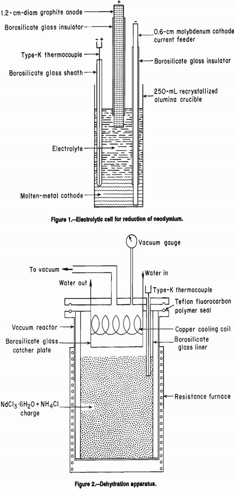
Figure 1 shows the cell used for the electrolytic reduc-tion of neodymium. A 5.5-cm-ID by 10.5-cm-tall recrystallized alumina crucible contained the electrolyte. A 0.6-cm- diam molybdenum rod provided the electrical connection to the molten-metal cathode. A 1.2-cm-diam graphite rod served as the anode. Both the cathode current feeder and the anode were sheathed with borosilicate glass tubes to fix the electrode surface area and accurately control the current density.
A 1,500-W resistance furnace supplied the heat. The temperature was controlled using an Omega 4002 temperature controller with a type-K thermocouple. The thermocouple, which was sheathed with borosilicate glass, was immersed in the molten-metal cathode. Direct current was supplied by a Hewlett-Packard rectifier operating in constant current output mode. A Curtis integrating ampere-hour meter measured the current passed through the cell and a Fluke 8060A digital multimeter measured the electric potential across the cell.
NdCl3, supplied by Research Chemicals, Phoenix, AZ, was 99.5 pct pure. Zinc, cadmium, and magnesium purities were 99.9, 99.9, and 99.8 pct, respectively. The ammonium chloride (NH4Cl), supplied by Mallinckrodt, Inc., St. Louis, MO, was reagent grade.
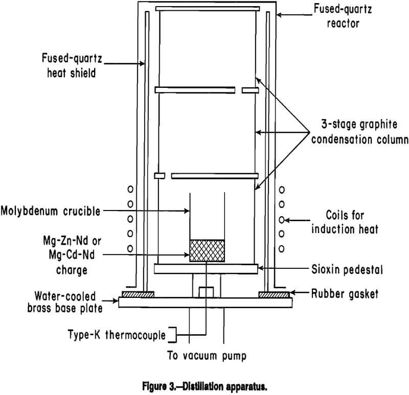
The drying apparatus for the neodymium chloride hexahydrate (NdCl3-6H2O) is shown in figure 2. A 2-L, 9.8- cm-OD by 26.0-cm-tall cylindrical Pyrex heat resistant glass container held the NdCl3 · 6H2O + NH4Cl charge. The Pyrex heat resistant glass liner was placed in a 10.0- cm-ID by 26.5-cm-tall 316 stainless steel vacuum reactor. The 316 stainless steel lid for the reactor was drilled and tapped with five ¼ national pipe thread (NPT) ports. Four of the ports were placed symmetrically around the circumference with the fifth dead center. These ports provided the throughputs for the cooling coil, vacuum port, vacuum gauge, and thermocouple well.
The cooling water circulated through a copper coil, 6.0- cm diam, constructed from ¼-in tubing, centered 5.0-cm down and inside the Pyrex heat resistant glass container. The coil passed through the lid using ¼-in tubing to ¼ NPT adapters placed on opposite sides of the lid. The vacuum port and vacuum gauge had ¼ NPT threads.
The type-K thermocouple was sheathed with borosilicate glass and used a ¼-in tubing to ¼ NPT adapter with a Teflon fluorocarbon polymer compression ferrule. All ports were vacuum tight.
Heat was supplied with a 1,500-W resistance furnace. The temperature was controlled with a type-K thermocouple and an Omega series CN-2010 temperature controller with ramp and soak capabilities.
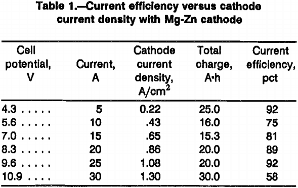
The main components of the vacuum distillation apparatus are shown in figure 3. The base metal, neodymium charge, was contained in a 2.5-cm-ID by 5.0-cm-tall molybdenum crucible. The molybdenum crucible was placed in a three-stage graphite condensation column. The lower stage, which held the molybdenum crucible, was 7.5 cm OD by 7.5 cm tall. The wall and bottom thickness was 0.5 cm. The upper two stages were 7.5-cm OD by 7.5-cm- tall cylinders. Each stage was separated by an 8-cm-diam graphite plate, which was machined so that it fit snugly between the upper and lower stages. The purpose of these dividers was two-fold: one was to hold the stages together; the second was to act as baffles to prevent the reflux of material back into the molybdenum crucible. This was accomplished by rotating the off-center 0.75-cm holes in each plate 180°.
The entire column was supported above the vacuum port by a refractory ceramic pedestal. A thermocouple, sheathed with a molybdenum tube, was fed through the vacuum port and was placed in contact with the bottom of the graphite column. The entire condensation column was surrounded by a cylindrical fused-quartz heat shield.
A fused-quartz bell jar, 10.0 cm ID by 43.0 cm tall, was used as the vacuum chamber. The quartz bell jar had a 2.0-cm annular flange around the open end, which sealed against a rubber gasket resting on a water-cooled brass base plate.
Vacuum was provided by a two-stage mechanical pump capable of a free air displacement of 100 L/min. The vacuum system was used to evacuate both the distillation apparatus and the alloying systems used to produce the binary alloys. In the case of alloying, a needle valve was connected to a port in the throat of the main vacuum line to bleed in 99.999 pct argon or helium.
Induction coils were placed around the quartz bell jar on the outside. The coils were at the load end of a 15-kW Power Trak 10,000 Hz induction heating system built by Inductotherm Industries, Rancocas, NJ. The power was controllable to 0.25 kW. The temperature was monitored by the display of the thermocouple output and compared with the temperature obtained from a Leeds and Northrup optical pyrometer aimed at the lower portion of the graphite condensation column.
Experimental Procedures
NdCl3 was obtained as NdCl3·6H2O which required dehydration before electrolysis. Block outlined a procedure for drying the salt. A 1:1-mole mixture of NdCl3·6H2O and NH4Cl was heated to 360° C over 72 h at a pressure of 0.01 to 0.1 torr. The NH4Cl sublimes at 360° C and was condensed on water-cooled copper coils. This procedure was followed to inhibit the formation of neodymium oxychloride (NdOCl), which has deleterious effects on cell performance because it increases the electrolyte’s resistivity, melting temperature, and viscosity.
Numerous electrolytes of binary and ternary chloride systems have been used in the electrowinning of rare-earth metals. The electrolyte, which was used in this study, was a 50:50 mole mixture of NdCl3-KCl. The mixture melts at 480° C and has a liquid density of 2.99 g/cm³. It is an eutectic with a relatively low increase in melting point with compositional changes that was desirable for experiments in which NdCl3 was not added during electrolysis.
Preparation of Cathode Alloys
Alloys of Mg-Zn and Mg-Cd were prepared by melting the pure metals in an inductively heated graphite crucible. The crucible containing the metals was placed into a vacuum chamber, which was evacuated for 1 h to assure thorough outgassing. The chamber was backfilled with high-purity argon, and the crucible and metals were slowly heated to 650° C, and held at that temperature until all the metal was molten. The induction field provided sufficient agitation for thorough mixing. Metal loss by evaporation during melting was less than 1.0 pct.
Nd-Fe alloy was prepared by arc melting on a cold copper hearth. The vacuum chamber was outgassed using a mechanical pump and flushed with high-purity argon several times. A titanium button was melted to getter traces of oxygen. After melting, if the titanium button appeared clean and shiny with no discoloration, it was assumed that oxygen was no longer present, and then the cathode metals were melted. The Nd-Fe cathodes were turned over and remelted at least seven times to assure homogeneity. The Nd-Fe alloy’s melting point was deter-mined to be 660° C using differential thermal analysis.
Cell Operation
One-hundred-fifty to three hundred grams Zn, Mg-Zn, Mg-Cd, or Nd-Fe were placed in the bottom of the electrolytic cell shown in figure 1. The molybdenum cathode current feeder was inserted, and 400 g of mixed electrolyte salts were placed in the cell container. After melting the electrolyte, the graphite anode was inserted to a depth of 2.0 cm. The cathode and anode surface areas were, respectively, 23.13 and 8.67 cm². The cell was operated at 650° ±10° C for these experiments.
Upon cessation of electrolysis, the anode, cathode current feeder, and thermocouple were removed, and the electrolyte was allowed to cool in the alumina crucible. Once cooled, the crucible was broken, and the cathode was separated from the frozen electrolyte. Any remaining electrolyte was removed from the cathode with a wire brush. The cathode was weighed, and current efficiency was calculated from the increase in cathode weight.
An experiment was made in which 50 A·h was passed through the cell that required periodic additions of NdCl3. Twenty grams of NdCl3 were added to the cell every 5 A·h. Approximately 100 g of cathode alloy was syphoned from the cell every 25 A·h. A 25-mL Pyrex heat resistant glass pipette was connected to a mechanical vacuum pump. The pipette was immersed into the bottom of the cell and vacuum was applied. Once the bulb was full with alloy, the vacuum was turned off, and the alloy was allowed to freeze in the pipette. The alloy was removed by breaking the pipette.
Distillation
Sixty grams of the neodymium-bearing cathode alloy was used for distillation. Figure 3 shows the distillation apparatus. The alloy was added to a molybdenum crucible and placed in the graphite condensation column. The graphite column was placed in a bell jar, and the system was outgassed for 1 h at 10-³ torr. High-purity argon was bled into the bell jar until a pressure of 400 torr was obtained, after which induction heating brought the alloy to 900° C. When the alloy was completely molten, the pressure was gradually lowered to 10-³ torr. The temperature was increased to 1,100° C and maintained for 15 or 30 min at 10-³ torr. After cooling, the neodymium was recovered by inverting the crucible and reheating under vacuum. The molten neodymium dripped from the crucible onto a cold copper hearth.
Results and Discussion
Zinc was tried as a molten-metal cathode because of its low melting and boiling points. Since zinc melts at 419° C, a relatively low operating temperature could be used. In addition, because zinc boils at 906° C, it was postulated that zinc should distill rapidly from neodymium.
Neodymium was electrodeposited into the molten-zinc cathode, but the current efficiencies averaged only 50 pct. Zinc became dispersed throughout the electrolyte at all current densities. Decreasing the operating temperature from 650° to 500° C did not improve the results. Although lowering the operating temperature to 500° C decreased the mobility of zinc in the electrolyte, the current efficiencies dropped to 40 pct. Cell performance was worse when the temperature was increased to 750° C. The zinc mixed freely with the electrolyte at temperatures more than 700° C, and current efficiency dropped to zero. In all cases, it was difficult to separate the solidified salt from the zinc cathode after electrolysis.
Magnesium-zinc alloys were tried as a replacement for zinc in an attempt to decrease zinc’s mobility in the electrolyte. Also, the addition of magnesium to zinc reduced the density of the molten-metal cathode, which would cause the neodymium to sink into the cathode faster.
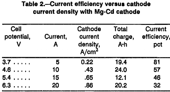
Table 1 shows the results of six experiments with a liquid Mg-Zn cathode. The current efficiency was affected by varying the operating current density between 0.22 and 0.65 A/cm². The current efficiency dropped to 58 pct at a current density of 1.30 A/cm². Furthermore, as with zinc, the separation of the frozen electrolyte from the surface of the Mg-Zn cathode was difficult. Dissolving the salt from the cathode with anhydrous ethanol revealed that surface topography was highly irregular. Increasing the current density increased the irregularity of the surface. The failure to recover all the cathode material is the reason for the scatter in the current efficiency data in table 1.
Although Mg-Zn cathodes performed better than zinc cathodes, the problem of the cathode mixing with the electrolyte prompted the study of Mg-Cd alloys as liquid-metal cathodes. The Mg-Cd cathode demonstrated no tendency to mix with the electrolyte. The cathode always had a smooth surface, which separated neatly from the electrolyte. There was no evidence of vaporization of the cadmium.
Results of the experiments with a Mg-Cd cathode (table 2) show that current efficiency decreased with increasing current density. The decrease in current efficiency with increasing current density may be explained by considering that at 650° C, neodymium metal is electrowon at the molten-metal cathode surface as solid dendrites. The dendritic neodymium must then alloy with the cathode. After alloying, the neodymium is afforded protection from the electrolyte. At low current density, the rate at which the neodymium dendrites enter the liquid cathode may nearly equal the electrodeposition rate. As the rate of electrodeposition is increased, the rate at which dendrites enter the molten cathode may not keep pace, which results in neodymium metal being solubilized.
The Mg-Zn and Mg-Cd cathodes were routinely loaded from 10 to 20 pct neodymium by weight during electrolysis. The viscosity of the cathode was relatively unchanged for neodymium concentrations up to 20 wt pct. However, neodymium concentrations more than 25 wt pct caused a noticeable increase in the viscosity of the cathode and a dramatic decrease in current efficiency. Apparently, a solid phase formed above 25 wt pct Nd.
A 50 A·h electrolytic experiment was made to determine the feasibility of operating a cell for longer periods. The cathode alloy was syphoned from the cell after the neodymium concentration reached 15 wt pct. The syphoning procedure went smoothly, and 100 g of molten cathode metal was removed at a time. Additional solid Mg-Cd was slowly lowered into the cell to maintain a desirable cathode depth.
Other metals and alloys were tried as molten-metal cathodes but none performed as well as the Mg-Cd cathode. Lead and bismuth were among the metals used. The experiments were performed as outlined above. Neither lead or bismuth mixed with the electrolyte and although chlorine evolved from the anode, no neodymium reported to the cathode.
Because neodymium’s major use is in Fe-Nd-B magnets, Nd-Fe, which is molten at 650° C, was tried as a liquid cathode. The alloy was solubilized by the electrolyte, and metal was lost to the bath even though the alloy was kept cathodic while heating the cell.
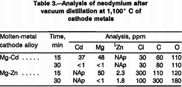
Table 3 shows the analysis of neodymium metal after vacuum distillation for 15 and 30 min. The neodymium recovered from the Mg-Cd cathodes was 99.97 pct pure; neodymium recovered from the Mg-Zn cathodes contained about 2.0 pct Zn after vacuum distillation.
Summary and Conclusions
Neodymium was electrowon from a NdCl3-KCl electrolyte by using molten-metal cathodes. High current efficiencies were obtained when electrowinning into Mg-Zn or Mg-Cd cathodes. The Mg-Cd cathode performed best because the metal separated cleanly from the electrolyte, and the neodymium obtained after vacuum distillation was of higher purity. The duration of electrolysis was extended, and the molten-metal cathode was easily removed and replenished, demonstrating that this procedure could operate continuously.
