Table of Contents
- Mineralogy
- Introduced Metallics
- Sampling & Preparing Ore for Treatment
- Chemical Analysis
- Treatment of Ore
- Oxidizing Roast
- Leaching with Dilute Sulphuric Acid
- Electrolytic Precipitation
- Kinds of Anodes
- Depolarizing Effect of Sulphur Dioxide Gas
- Step System of Electrolytic Precipitation
- Copper Electrolysis Process Explained
Experiments on a Porphyry Copper Ore: This research was done partly in the non-ferrous laboratory of the Department of Metallurgy of Columbia University, under the direction of Dr. Edward F. Kern, and completed elsewhere. Acknowledgment is due to Prof. Arthur L. Walker, Dr. Edward F. Kern and Dr. William Campbell of the Department of Metallurgy, for their kind advice and for the inspiration derived from their instruction.
This report is given under the following heads: Petrographic Description (Microscopic Study); Sampling and Preparing Ore for Treatment; Chemical Analysis; Treatment of Ore.
Mineralogy
(Minerals are grouped for interpretation purposes and are arranged in each group in approximate order of abundance)
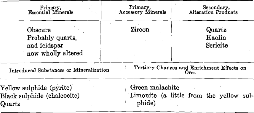
The original character of the rock has been much obscured by modification. The variable texture indicates that the original rock was much brecciated. Silicification seems to have been a prominent feature. Some of the quartz appears to be remnants of primary grains. It must have been primarily an acid intrusive, which, after having been fractured and brecciated, has become still more acid by silicification. There appear to be recorded several sets of movements. The special features of most importance seem to be as follows:
Ground Mass
This shows variable texture, fragmental (brecciated). The whole is so much modified that the fragmental character is not plain. Most of
the grains seem to be quartz. The only evidences of feldspar are those areas judged to be slightly kaolinized and areas of sericite. The fragmental character of the rock is somewhat further emphasized by the manner in which the metallics are distributed. These are distributed in such a way as to suggest an original fragmental (breccia), into the interstices of which were introduced the yellow and black sulphides. Certain streaked areas are much clearer than the rest of the ground mass and generally free from introduced metallics. These are filled with what is plainly introduced quartz, and they seem to represent old fractures. It is difficult to say just what relation these bear to the mineralization periods; they may possibly represent the closing stages of silicification.
Introduced Metallics
These consist of yellow pyrite and black chalcocite. The yellow sulphide seems to be a little too yellow for typical pyrite and not quite yellow enough for chalcopyrite. The yellow sulphide bears evidence of having been fractured and somewhat crushed. The fractures are healed with the black sulphide. The fractures extending across the grains of yellow sulphide end abruptly at their margins, and do not continue into
the adjacent grains of ground mass. Under the microscope, there may be seen areas of yellow sulphide, veined and rimmed with black sulphide; the whole is rimmed with a narrow band of sericite and, in some cases, of quartz. It is evident that the history of this rock is very complicated.
It would seem, therefore, that two periods of mineralization are here represented: first, the decomposition of the yellow sulphide, followed by sufficient movement to cause fracturing and slight crushing, either during the closing stages of its deposition or immediately thereafter; second, the introduction of the black sulphide, which was deposited in the previously formed and fractured yellow sulphide and as an envelope surrounding the smaller grains of the yellow sulphide. Silicification very likely accompanied all of these changes. According to this interpretation, the rock is a silicified and mineralized brecciated, acid intrusive (quartz porphyry), in which two periods of mineralization are represented. There is no absolute proof in these slides as to the source of the secondary mineralization, i.e., the chalcocite.
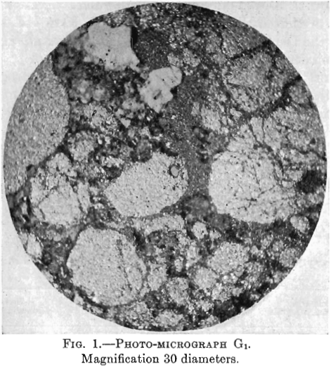
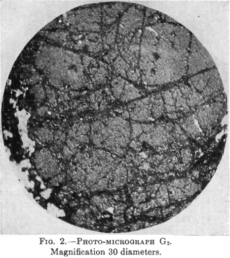
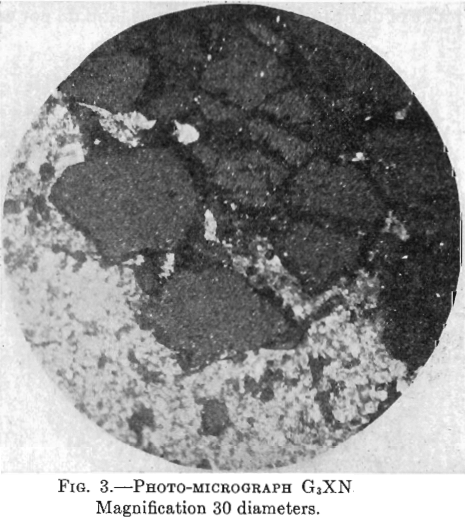
Photo-micrographs G1, G2, G3XN, Figs. 1, 2, 3.
(.Magnification 30 Diameters).
G1—The large patches, light in shade, comprising the greater part of
the photomicrographs, are yellow pyrite. There are two large patches, and several smaller ones, light in shade, but differing in appearance from those representing pyrite, in that they have a surface of homogeneous shade. These are quartz. The darker portions, occurring as spots and veinlets cutting the yellow pyrite, are of chalcocite.
G2—In this photomicrograph, the black masses and veinlets of chalcocite are very strongly marked. There is also some white non-metallic material.
G3XN—This photomicrograph was taken with crossed nicols of a slide containing more non-metallic material. The yellow pyrite here shows as large patches, quite dark, intersected by black veinlets of chalcocite. There is much white non-metallic material which, being doubly refracting, shows white as in the other photomicrograph (taken with upper nicols out), while the pyrite, not being doubly refracting, shows darker.
Sampling & Preparing Ore for Treatment
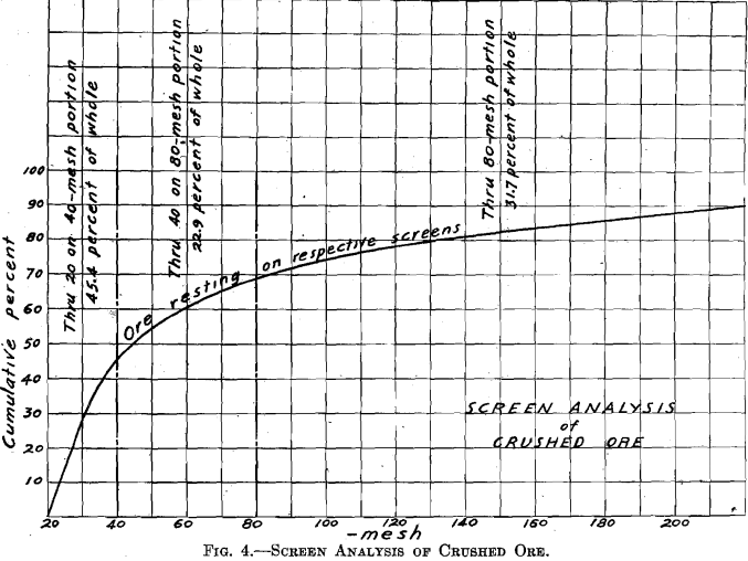
The ore was received in lump form. Five hundred pounds were crushed to pass a 4-mesh screen, using the gyratory crusher followed by the cone-and-ring sample grinder. A sample for analysis was cut out and ground through 100 mesh. One-quarter of the lot was then cut out for treatment. This was passed repeatedly through the sample grinder (which was set up so as to grind finer), until all passed a 20-mesh screen. This one-quarter was then thoroughly mixed by repeated coning, and then split by split shovel. One resulting one-eighth was retained for treatment and will be called “Whole through 20 mesh.’’ The other resulting one-eighth was sized, producing the portions: Through 20 on 40 mesh, 45.4 per cent, of whole; through 40 on 80 mesh, 22.9 per cent, of whole; through 80 mesh, 31.7 per cent, of whole. (The screen analysis of the crushed ore is given in Fig. 4.)
Chemical Analysis

Treatment of Ore
It has been seen that the ore is mainly a sulphide. Copper sulphide ores, which contain an excess of silica, have been heretofore usually treated by mechanical concentration followed by smelting. But this ore, like much of the disseminated orebodies of the Southwest, contains a portion of its valuable copper contents in an oxidized condition—malachite. Mechanical concentration on pure sulphides makes usually a saving of 66 per cent.; and when there is an oxidized component the saving is likely to be still lower. For this reason, it was decided to make a test on this ore by a leaching method. The method selected comprises:
- Oxidizing roast;
- Leaching with dilute sulphuric acid;
- Electrolytic precipitation of the dissolved copper.
Oxidizing Roast
A series of four roasts was made in a gas muffle furnace (17½ by 11½ by 4 in.—inside measurement). In order that the relative roasting qualities of coarse and fine material, as well as the most suitable temperature, might be determined, 300 g. of through 20 on 40 mesh material and 300 g. of through 80 mesh material were roasted, in two 7-in. roasting dishes. The temperature of roasting was measured by a thermo-electric pyrometer. Samples to determine the progress of roasting were taken at ½-hr. intervals. These samples were ground through 100 mesh and then tested as follows: One gram of sample was boiled in a covered casserole for 20 min. with 150 cc. of water. The soluble copper thus obtained is reported in per cent, copper soluble in water. After filtering and washing, the same portion of sample was boiled in a covered casserole for 20 min. with 150 cc. of dilute hydrochloric acid (100 cc. of concentrated hydrochloric
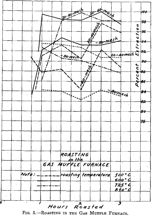
acid diluted to 1,000 cc.). The soluble copper thus obtained is reported as per cent, copper soluble in dilute hydrochloric acid. The sum of these two is reported as the per cent, of total soluble copper. The difference between this and the total per cent, of copper found in the sample is reported as per cent, insoluble copper. By dividing per cent, of total soluble copper by total per cent, of copper in sample, per cent, extraction was determined.
On referring to Fig. 5, Roasting in the Gas Muffle Furnace, where material through 20 on 40 mesh and material through 80 mesh were
roasted side by side in separate roasting dishes, it will be seen, by leaching with dilute acid, that the material through 20 on 40 mesh always gave a higher extraction than the material through 80 mesh. As regards temperature, the roast conducted at 850° C. gave the poorest extraction, the temperature being too high. (The series of roasts indicates that at temperatures above 725° C. the resulting copper oxide forms insoluble compounds.) The roast conducted at 500° C. gave better extraction, but, as shown by subsequent roasts, the temperature was too low to secure the best extraction on leaching. Roasts conducted at 600° C. and 725° C. are equally good on material through 20 on 40 mesh; but on material through 80 mesh, the 600° temperature gave material which yielded the
best extraction. Consequently the temperature of 600° C. was selected as the best for subsequent roasting in the large gas roasting furnace.
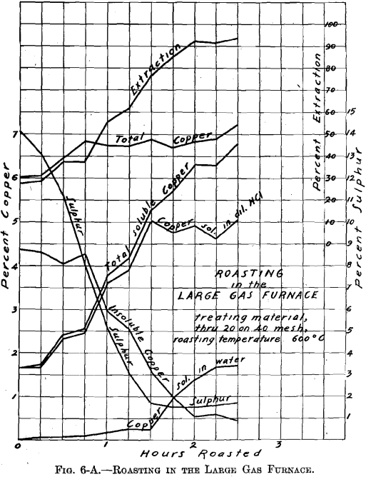
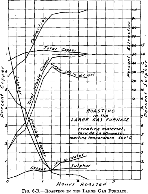
There was no muffle in the large gas roasting furnace and its operation was similar to that of a gas-fired reverberatory furnace. The hearth, which was removable, consisted of a sheet-iron pan, lined with firebrick (22½ by 9 in.—inside measurement). Two series of roasts were made; viz., A-Series and B-Series. Eight pounds of material were roasted per charge. The temperature of 600° C. was held constant. The materials roasted were: through 20 on 40 mesh; through 40 on 80 mesh; through 80 mesh; whole through 20 mesh. In all about 100 lb. of ore were roasted. Samples were taken during roasting at ¼-hr. intervals. Of the several
roasts made of one size material, in the A-Series and in the B-Series as through 20 on 40 mesh, average samples were made. These samples were ground through 100 mesh, and tested for soluble copper, in the same manner as the samples resulting from the roasting in the gas muffle furnace.
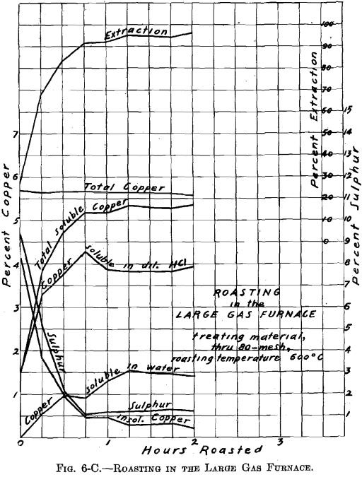
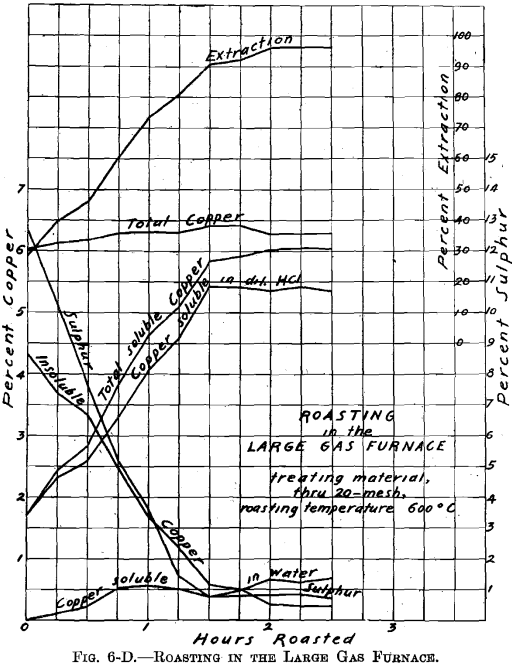
Referring to Figs. 6-A, 6-B, 6-C, 6-D, Roasting in the Large Gas Furnace, it will be seen that an extraction of 96 per cent, was secured in all roasts, except on the through 20 on 40 mesh material, which was but 93 per cent. The roasts were all carried on for a longer time than was necessary. An inspection of the curves will enable one to determine the most desirable time of drawing the roasts.
Leaching with Dilute Sulphuric Acid
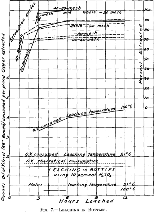
In order to forecast, as well as could be done in a small way, what might be expected in practice, regarding extraction and acid consumption, the following leaching experiments were made: 20 g. of roasted ore, together with 200 cc. of 10 per cent. H2SO4, were introduced into glass-stoppered bottles, which were continually shaken. Two tests were made, one at a temperature of 21° C., the other at a temperature of 100° C. The material here leached was in the same condition, as regards degree
of comminution, as when it left the sizing sieve, except as the roasting may have affected it. It is to be noted that it was not so with the samples of roasted materials earlier tested for solubility of the copper contents, and which were all ground through 100 mesh before boiling in the casserole with water and dilute hydrochloric acid.
In the test made at 21° C., the extraction ranged from 72 to 90 per cent. The extraction was not improved by continuing the operation longer than 6 hr. The acid consumption was moderate, being 2.0 lb. of oil of vitriol (66° Be.) per pound of copper extracted, as compared with 1.65, lb. theoretically required to dissolve 1 lb. of copper existing as oxide. The test which was made at 100°,C. gave an extraction of 90 per cent, with the through 20 on 40 mesh material, while with all other materials the extraction was 100 per cent. The acid consumption was somewhat higher, as Fig. 7 shows. The time required for efficient leaching was between 3 and 6 hr. Nothing was gained by increasing the time of leaching beyond 6 hr.
Electrolytic Precipitation
Electrolytic Plant
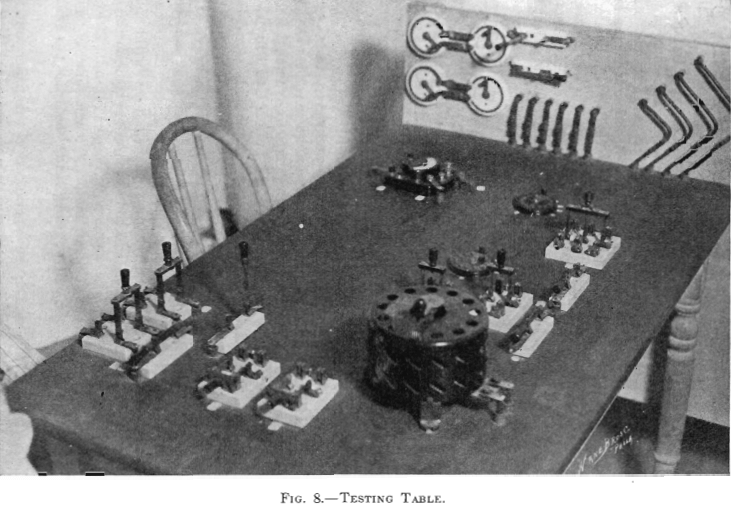
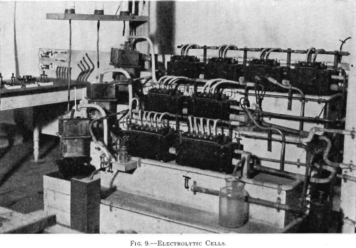
The electrolytic plant, designed for experimenting in the deposition of copper from solution with insoluble anodes, comprised a motor-generator set, circulating pumps, electrolytic cells, and a testing table. (See Figs. 8, 9, and 10.)
The motor-generator set used was a Robbins & Meyers ¼-hp., 110- volt, 60-cycle, 1,750 r. p. m., single-phase motor, belted to their 0.125-kw., 10-volt, D. C., 1,750 r. p. m., compound-wound generator.
A small acid-proof pump could not be found in the market, so a single-acting acid-proof pump was designed. Four pumps were made. A 2-oz. syringe, No. 135, made by the American Hard Rubber Co., was used as a pump barrel. A block of dry maple was suitably bored. There were two ball valves; the seats were rings of ¼-in. hard rubber; the balls, glass agates. The balls were ground into the seats with emery. The seats entered the cavities bored for them snugly. P. & B. acid-proof paint secured the seats in place so that there was no leakage. The syringe, the suction pipe, and the discharge pipe, entered holes in the maple block prepared for them. Water-tight connections were made by suitable soft-rubber packing rings. The Robbins & Meyers, 1/8-hp., 110-volt, 60-cycle, 1,750 r. p. m., single-phase motor, through suitable pulleys and gears operated the four pumps, which made 35 strokes per minute. (See Fig. 10.)
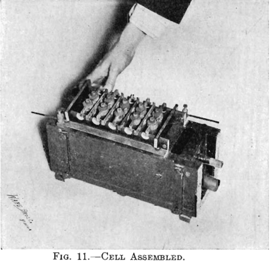
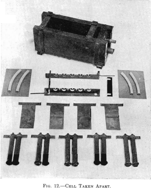
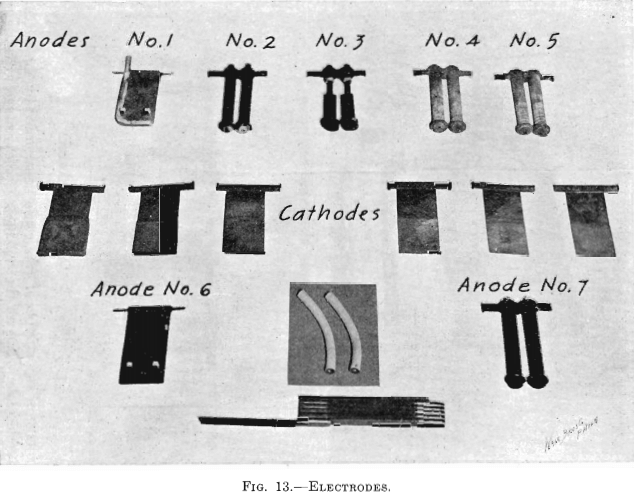
The electrolytic cells used in the experiments of this paper were four cells with one cathode each, two cells with two cathodes each, and two cells with four cathodes each. Each cell had one more anode than cathodes. (See Fig. 9.) Figs. 11 and 12 show one cell with four cathodes, assembled and taken apart. The electrodes were spaced ¾ in. from center to center. Anode No. 6, seen in Fig. 13 (lower left-hand corner), was
used in Tests Nos. 1 and 2. It was made from a sheet of lead (8 lb. to the square foot), 2½ in. wide and of the proper length. The upper edge was wrapped around a piece of No. 6 bare copper wire by which it was suspended in the cell. Cathodes may likewise be seen in Fig. 13 (middle row). The cathode was made of a sheet of thin copper attached to a copper clamp by which it was suspended in the cell. There were four insulating blocks of hard rubber, 1 by 1 by ½ in., beneath the cell. There were four pieces of hard rubber, 1 by 1 by 5/16 in., with a 3/16 in. upward projection for insulating and holding the bus-bars in place. In Fig. 12, just below the cell, the bus-bars may be seen. The bus-bar was comprised of a 1 by 1 in. brass angle and a 1 by ¼ in. hard-rubber strip. The rubber strip was bolted to the vertical leg of the brass angle. There were two pieces of hard rubber spacing pieces used for holding the bus-bars rigidly in place. The method of connecting the electrodes with the bus-bars was similar to practice. The brass and the hard rubber of the bus-bars were so cut that when the horizontal arms of the electrodes rested on them, on one side the arms of the anodes rested on the brass plus conductor while the arms of the cathodes were insulated by hard rubber, and on the other side the arms of the anodes were insulated by hard rubber while the arms of the cathodes rested on the brass minus conductor. The binding posts with No. 6 bare copper wire served for connecting between cells. (See Figs. 9, 11, and 12.)
Quite elaborate piping systems about the cells may be seen in Fig. 9. The elevated temperature tank and the cells of a step were connected by 1-in. lead pipe, the connections to and from the step circulating pump were made by ½-in. lead pipe. For the progressive circulation of the electrolyte through the plant, ½-in. lead pipe was used. The sulphur dioxide gas was conveyed to the cells by its system of lead piping. The gas was supplied from a cylinder of liquid gas. The gas cylinder was connected by small rubber tubing to the end of a 2-ft. length of 1-in. lead pipe. From the rear side of this pipe, four ½-in. lead pipes, leading to different parts of the plant, passed beneath the cells. (See Fig. 9, in foreground.) There was placed horizontally above the cells of each step a ½-in. lead pipe. This pipe was fitted with ¼-in. tee connections which were connected to the hollow anodes, used in Tests Nos. 3 and 4, by rubber tubing. Bottles were introduced between the ends of the four distributing pipes and these horizontal pipes, just mentioned, in order to indicate the amount of gas flowing. The four indicator bottles for judging the rate of flow of the gas contained a little water through which the gas bubbled. A screw clamp on the rubber tubing connection, between each distributing pipe and its indicator bottle, adjusted the distribution of gas.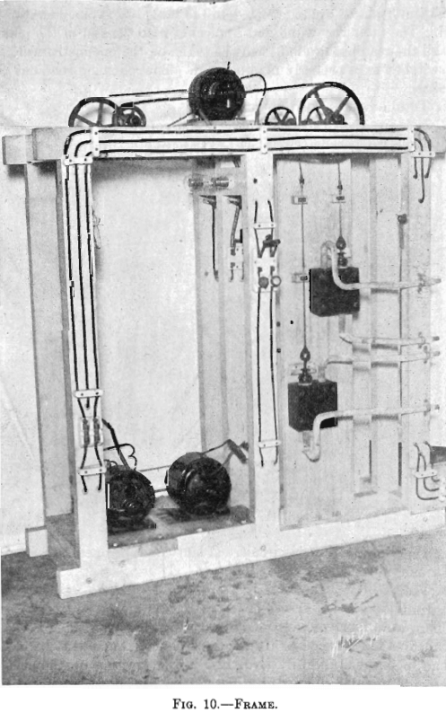
A poplar kitchen table, with top 30 in. by 48 in., was selected for the testing table. A Weston miniature, precision, direct-current volt-amp-meter was used (Model 280 triple-range portable volt-ammeter, Weston Electrical Instrument Co., Newark, N. J., Bulletin No. 8, 1912). The scales were: 150, 15, 3 volts; 30, 15, 3 amperes. The instrument was permanently placed and connected on the table top at the operator’s left hand. The table was wired and connected with the rest of the plant, so that all the readings desired might be taken on the one instrument when the switches were properly manipulated. The following readings could be taken:
- Total amperes, load on generator.
- Amperes, No. 1 load circuit. (Plant could be operated as one circuit or as two parallel circuits.)
- Amperes, No. 2 load circuit. (Plant could be operated as one circuit or as two parallel circuits.)
- Generator volts.
- Individual volts across cells.
There were fourteen voltage wires, each terminating at one end (the cell end) in a tee connector. In the foreground of Fig. 9 may be seen the cell end of one voltage wire (No. 12). In connecting up the cells (arrangements might be varied in different tests), there was always to be found close to the cell the cell end of a voltage wire. In making series connections between consecutive cells, No. 6 copper connecting wires from the respective binding posts of the bus-bars of the two cells entered a tee connector, one leg of which was permanently attached to the end (cell end) of a voltage wire. All the fourteen voltage wires passed to the testing table where they connected to two 13-point circular switches. The switch to the operator’s left had connected to it wires Nos. 1 to 13, while the switch to his right had connected to it wires Nos. 2 to 14. On properly setting the two 13-point switches and throwing the three-pole double-throw switch adjoining, the individual volts across cells, or the
sum voltage of any number of cells, could be recorded by the instrument on suitable scale. Not all the cell ends of the voltage wires were connected in any one test. When the plant was wired up for some one test, the voltage wires in use were noted and the corresponding switch points on the table top were tagged for the operator’s use. All switch points connected with unused voltage wires were dead.
The generator field rheostat is seen in the foreground of Fig. 8. To the operator’s left, on the vertical panel, were four battery rheostats, connected in parallel, serving as a variable load in series with the cells in load circuit No. 2. These battery rheostats could be short circuited, when the generator field rheostat would give the desired voltage regulation. When a lower voltage was desired than the field rheostat could give, then the variable resistance in series was used.
Test No. 1.—Arrangement A, in “Example of Step Arrangement of Plant,” was employed, operating No. 1 Step and No. 2 Step and omitting the Finishing Step. No. 1 Step had four cells, connected in series, each with one cathode. No. 2 Step had two cells, connected in parallel, each with two cathodes: this combination will be spoken of as one cell of four

cathodes. Note that the plant was operated with one-third as many cells as are indicated in the diagram, Fig. 16 (Example of Step Arrangement of Plant—A). Evaporation was compensated for by adding sufficient water to the temperature tank of No. 1 Step and to the temperature tank of No. 2 Step. The relative amounts of water for each step were proportional to the step surface exposed to evaporation. Consequently the overflow to the sump of No. 2 Step was equal in volume to that of the copper solution fed to the temperature tank of No. 1 Step. (See Table I.)
Current density of 20 amperes per square foot was selected for No. 1 Step. The area (sum of the two sides) of the cathode is 0.0824 sq. ft., therefore a current of 1.648 was supplied. The volume of copper feed solution required for 12 hr., in order to supply the cells of No. 1 Step with an amount of copper equal to that deposited in that step by the current selected plus the copper carried on by the progressive circulation so that the electrolyte would remain constant in composition, was determined as follows:
1.648 x 4 x 12 x 1.1855 x 0.90/0.75 x 0.06 = 1,872 c. c. copper feed solution required for 12 hr.
Where,
Current amperes……………………………………..1.648
Number of cells in series, No. 1 Step……………..4
Duration, hours………………………………………….12
Theoretical copper deposited by 1 ampere-hour, grams…………1.1855
Current efficiency, per cent., assumed……………………………90
Copper deposited in No. 1 Step, expressed as per cent, of that in feed……………..75
Copper in feed solution, per cent………………………..6
1,872 c. c. of No. 1 Step electrolyte, containing 1.5 per cent, copper, overflowed from the last cell of No. 1 Step to the temperature tank of No. 2 Step. This supplied No. 2 Step with an amount of copper equal to that deposited by the current in that step, plus the copper carried on to the sump by the progressive circulation, as the following calculation shows:
1.648 x 1 x 12 x 1.1855 x 0.90/0.75 x 0.015 = 1,872 c. c., overflow of No. 1 Step electrolyte, required for No. 2 Step.
Where,
Number of cells in series, No. 2 Step………………………………………….1
Copper in overflow of No. 1 Step electrolyte, per cent…………………1.5
The strength of the electrolyte in H2SO4, which is developed by the acid liberated by the copper on deposition, was determined as follows:
No. 1 Step.
0.06 x 0.75 x 1.54 = 0.069 (or 6.93 per cent.).
Where,
Copper in feed solution, per cent…………………………….6
Copper deposited in No. 1 Step, expressed as per cent, of that in feed…………………….75
H2SO4 freed per unit of copper deposited……………………………1.54
No. 2 Step.
0.06 x 0.9375 x 1.54 = 0.0866 (or 8.66 per cent.).
Where,
Copper deposited in Nos. 1 and 2 Steps, expressed as per cent, of that in feed…………………..93.75
In starting up the plant, each step was supplied with the necessary volume of electrolyte to put it in operation. The composition of this initial charge of electrolyte in copper and acid was that which the above calculations indicate and which may be seen in Table I. The results of this test show that when employing the Step Arrangement of Plant, and when adding water to each step to compensate for evaporation, the initial values of copper and acid contents of the electrolyte remain constant during the electrolysis. The results of this test also show the performance when copper is deposited, using insoluble lead anodes. (See Fig. 9; Tables I and II; and Fig. 16, Diagram Example of Step Arrangement of Plant—A.)
Test No. 2.—Arrangement A, in “Example of Step Arrangement of Plant,” was employed, using No. 1 Step, No. 2 Step, and the Finishing Step. The arrangement of the cells in Nos. 1 and 2 Steps was the same as in Test No. 1. The Finishing Step had two cells, connected in parallel, each with four cathodes; this combination will be spoken of as one cell of eight cathodes. The operation of the Finishing Step of this test will be discussed in Test No. 4.
In order to simplify the operation, a weaker copper feed solution was made for No. 1 Step by adding 1,170 c. c. water to 1,872 c. c. of 6.0 percent, copper solution, producing 3,042 c. c. of feed solution containing 3.7 per cent, copper, which was used for the 12-hr. run. This supplied No. 1 Step with the same amount of copper as in the previous test and with the water necessary to compensate for evaporation. There should have overflowed from Step No. 1, during the 12-hr. run, 1,872 c. c. of solution containing 1.5 per cent, of copper and 6.93 per cent, of H2SO4. When, as in Test No. 1, evaporation in No. 2 Step is compensated for by the addition of an equivalent amount of water, this becomes the step electrolyte with 0.375 per cent, of copper and 8.66 per cent, of H2SO4. But in this test no water was added to No. 2 Step, so assuming evaporation to be the same in amount as during the preceding test, namely 925 cc., there should have overflowed to the sump 1,872 — 925, or 947 cc. solution of the following composition:
0.00375 x 1872 x 947 = 0.00743 (or 0.743 per cent.) copper.
0.0866 x 1872/947 = 0.171 (or 17.1 per cent) H2SO4.
Note that in Test No. 2, as well as in Test No. 4, the initial charge of electrolyte to all steps deviated slightly in H2SO4 composition from the value which was calculated that it should have been. There was charged to No. 1 Step, a solution containing 6.24 per cent. H2SO4, instead of 6.93 per cent.; to No. 2 Step and to Finishing Step, 15.4 per cent. H2SO4, instead of 17.1 per cent.
The results of this test show that when employing the Step Arrangement of Plant as outlined above, and which differs in some details from the method used in Test No. 1, and when supplying initial charges of electrolyte of the compositions stated, these initial values remain constant in both copper and acid. The results of this test also show the performance when copper is deposited, using insoluble lead anodes. (See Figs. 9, 15, and 16; Tables I and II.)
Test No. 3.—But one electrolytic cell was used in this test. The intention was to introduce sulphur dioxide gas into the electrolyte during electrolysis in all subsequent work, so this test was run as a preliminary test to determine the best method of introducing the gas as well as the most suitable anode, in order to secure the best depolarizing effect.
Kinds of Anodes
See Fig. 13: Anodes Nos. 1, 2, 3, 4 and 5, top row, counting from left to right; Anodes No. 6, lower left corner; No. 7, lower right corner.
Anode No. 1 was the lead Anode No. 6, used in Tests Nos. 1 and 2, so modified that SO2 could be introduced into the electrolyte. Sufficient width and length was cut from one side and the bottom of Anode No. 6, as formerly used, so as to permit of attaching a ¼-in. lead pipe, without increasing its size. This lead pipe was closed at the immersed end, and had its horizontal leg perforated on the upper side with three No. 50 drill holes (about diam.), equally spaced. It was thought that the placing of the perforations thus would give an even distribution of the gas over the surface of the anode. (See Fig. 13, Anode No. 1.)
Anode No. 3 was made of lead pipe to imitate in form the carbon anode (No. 7). The main part is a piece of a ½-in. lead pipe. The bottom end was closed with a disk of lead in which was drilled a 1/8-in. hole (the same size as the central channel in the carbon anode). A short piece of ¼-in. lead pipe was forced into and burned to the upper end of the ½-in. lead pipe. To this ¼-in. lead pipe rubber tubing was attached for supplying the sulphur dioxide gas. A soft rubber washer was placed on the pipe, near its lower extremity, to act as an insulator for preventing the occurrence of short circuits in the cell. Such a rubber washer was similarly placed on all other round anodes. This soft rubber washer had the same office as the hard rubber pegs of the flat lead anode (No. 6). The complete anode comprises a pair of these lead pipes which are rigidly held in a special copper clamp. (See Fig. 13, Complete Anode No. 2.)
In Anode No. 3, a ¼-in. lead pipe extends through a short section of a ½-in. lead pipe, which enables it to be held firmly in the standard copper clamp. A piece of charcoal free from flaws was cut exactly ¾ in. square by 2½ in. long, and bored so as to fit snugly over the ¼-in. lead pipe. The sulphur dioxide gas enters the electrolyte from the bottom of the ¼-in. lead pipe. (See Fig. 13, Anode No. 3.)
Anode No. 4 is of carbon. The carbon tube from which the anode was made is ¾ in. outside diameter, 1/8 in. inside diameter and 12 in. long. This is an electric-arc carbon, incomplete in manufacture, and made by the National Carbon Co. Were it completed, the center channel would be filled with another grade of material, and then it would be a standard carbon for use in an electric arc for industrial purpose. This anode had a number of small holes made with a No. 50 drill, entering radially to the center channel. (See Fig. 13, Anode No. 4.)
Anode No. 5 differs from Anode No. 4 in that saw cuts were made instead of drill holes. These saw cuts extend half way through the carbon tube intersecting the center channel. (See Fig. 13, Anode No. 5.)
Anode No. 7 differed only from Nos. 4 and 5 in that it had no lateral perforations, the gas entering the electrolyte from the bottom extremity of the center channel. (See Fig. 13, Anode No. 7.)
Depolarizing Effect of Sulphur Dioxide Gas
On the assumption that all chemical energy is transformed completely into electrical energy, it was found by calculation that when no depolarizer is used, in a copper sulphate electrolyte, the theoretical counter E. M. F. of polarization is 1.22 volts, and when sulphur dioxide is used as depolarizer, the theoretical counter E. M. F. of polarization is—0.15 volt. Thus, theoretically, sulphur dioxide gas should reduce the polarization by 1.37 volts, changing the polarization of the cell from 1.22 volts opposing the generator to 0.15 volt, pulling with the generator. Consequently in this experiment a reduction of polarization of 1.37 volts has been taken as the standard of perfection. In the calculation of the counter E. M. F. of polarization, the correction term of absolute temperature times the temperature coefficient of the electrical energy was neglected, because its value is unknown. The results obtained were somewhat influenced by the omission of this correction term.
Polarization volts were determined as follows: During the test, when running at the current density desired, Reading 1 was taken of amperes and volts. By suitably manipulating the generator field rheostat, together with the series resistance in the circuit, the current was reduced appreciably. New current value, together with corresponding volts, was quickly recorded, giving Reading 2. The current was quickly brought back to its running value when Reading 3 was again taken of amperes and volts. Reading 3 should correspond to Reading 1. If it did not, the system was allowed to assume again its normal constant conditions and the same operation was repeated. All the readings were taken in a few seconds.
Example illustrating determination of polarization:
Reading 1, at C. D. 8 amperes per sq. ft.,
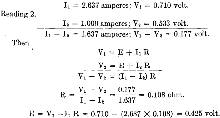
R equals ohmic resistance, made up of resistance in the solid conductor, contact resistance, and resistance in the electrolyte. This is constant.
E equals polarization voltage, constant at any one current density. It is assumed that during the time of taking Readings 1, 2, 3, E does not vary. This is proved when Reading 3 checks Reading 1. Results were not recorded unless this was the case.
On trying out the Anodes Nos. 1, 2, 3, 4, 5, 7, which were supplied with sulphur dioxide gas, it was found that with Anodes Nos. 1, 2, 3 there was no reduction in polarization at all. The reason Anode No. 3 was tried was because, from a few random tests with the carbon anode, it had been learned that with this anode there would be beneficial reduction in polarization by the introduction of sulphur dioxide gas. It was thought that charcoal, being quite porous, might promote anode efficiency on account of its known property of occluding gases. A charcoal rod, when used as anode, was found to have too high resistance to permit current to pass, therefore the combined lead-charcoal anode (No. 3) was made. This anode did permit current to pass, but, contrary to expectation, there was no beneficial depolarization.
The carbon anodes Nos. 4 and 5, the former with radial holes and the latter with saw cuts, were tried with their submerged ends of central channel open. Then they were tried with their submerged ends plugged, forcing all the gas entering the electrolyte out through the radial holes and
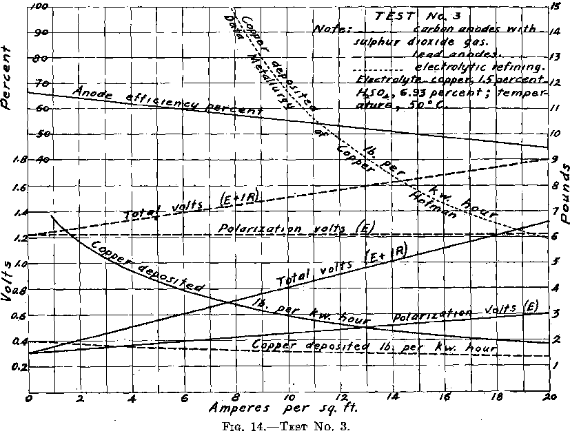
saw cuts. A variety of arrangements of holes and saw cuts were tried. Finally Anode No. 7, carbon anode with central channel extending through (not plugged) and with no other opening (neither radial drill holes nor saw cuts), was tried. The gas was delivered into the electrolyte entirely from the lower extremity of the anode. The depolarization efficiencies of Anodes Nos. 4, 5, 7 were equally good compared one with the other. Therefore Anode No. 7, being the simplest in form as well as one of the most efficient, was selected to be used in Test No. 3 and in Test No. 4. Readings were then taken from which Fig. 14 has been drawn. It is to be noted that during this test, sulphur dioxide gas was admitted through every anode, at such a rate that there was a gentle bubbling of the gas in the electrolyte.
Depolarization was not always equally good with the same carbon anode. It was generally only with a new carbon anode, when on closing the circuit permitting current to pass at current density of 20 amperes per square foot, that a total voltage reading as low as 0.60 volt might be recorded. This extremely low voltage always rose to some higher value which remained constant during the test. A subsequent test with the same anode generally gave the first voltage reading higher, likewise, the reading of the constant value higher. When depositing copper with a current density of 20 amperes per square foot, at one stage of the experimenting it appeared that the total voltage could be held at 0.9 volt, at a later stage, 1.2 volts, while Test No. 4 recorded 1.3 total volts. Apparently a new anode, when first put into use, is more efficient in reducing polarization than subsequently. This may partially account for variations in tests on the same anode. From time to time there was considerable variation in the ohmic resistance of cell (due to contacts), which may account for some of this variation in total volts.
Finally, after completing all the regular readings for the curve sheet, a little further experimenting was done. Ten anodes were used in a test. Gas was admitted by the ten anodes, by four anodes only, and by six anodes only. The reduction in polarization was as good when admitting gas by four anodes or by six anodes as when admitting gas by all ten anodes. The only difference noticed was that the gas was required to flow through the anodes admitting gas somewhat faster than before— probably the volume of gas entering was no more.
In Test No. 3, when using different kinds of anodes, beneficial reduction of polarization was only secured when carbon anodes were used, indicating that the nature of the anode is important. When using the carbon anode, equally good results were secured with all forms of the carbon tube (National Carbon Co. tube). It mattered not whether they were perforated by drill holes or saw cuts, for admitting and distributing the gas to the electrolyte, or whether it entered by every anode. All that was necessary was that the anode should be a carbon tube, with sufficient sulphur dioxide gas admitted to the electrolyte in some way. It appears that the quantity of sulphur dioxide gas required is that necessary to keep the electrolyte saturated with the gas.

Referring to the Tossizza patent, which states: “I have thought to use insoluble anodes kept in contact with sulphurous acid and to utilize the known depolarization properties of the said sulphurous acid;” “These anodes can be made of carbon.” From the above quotations, together with the results obtained in this test, I infer that Tossizza experimented only with carbon anodes. (See Figs. 8, 9, 10, and 14.)
Test No. 4.—The operation of this test differed from Test No. 2 only in that carbon tube anodes were used in place of the lead anodes, and sulphur dioxide gas was introduced into the electrolyte. Were depolarization perfect in operation, then for each equivalent of copper deposited, two equivalents of H2SO4 would appear instead of one when sulphur dioxide gas is not used. In this test, the initial charges of electrolyte to the different steps had the degree of acidity which had been determined suitable for Tests Nos. 1 and 2 where SO2 gas was not employed. Consequently, when using sulphur dioxide gas as depolarizer, the electrolytes became more acid in proportion to the anode efficiency as the electrolysis progressed. The tabulation of Test No. 4 shows a decided increase in acidity. (See Table I.) When the anode efficiency is known and when the initial electrolyte charged to the cells is made correspondingly more acid, then the electrolyte should remain constant in acid contents. Anode efficiency is discussed fully in Test No. 3. It was there estimated by percentage reduction in polarization rather than by increased acidity, as with a fine electrical instrument this method was thought to be more accurate than analytical methods. By the electrical method, results were recorded instantaneously, while the determination of the sulphuric acid by chemical analysis would require days to secure a series of results.
Referring to the tabulation of Test No. 4, where the average results of readings taken half-hourly are recorded, quite a saving in power in Nos. 1 and 2 Steps of Test No. 4 over Test No. 2 will be seen.
Finishing Step.—The curve sheet of the Finishing Step (Fig. 15) represents the performance of this step of the process in Tests Nos. 2 and 4.
The 5,210 cc. of electrolyte, containing 0.743 per cent, copper and 15.4 per cent. H2SO4, with current of 1.648 amperes passing, required theoretically, 19.85 hr. to completely deposit the total copper contents. In these tests, when carried to the 19.85-hr. point, the results were:

While the extraction is high and current efficiency good in both tests, it would not be desirable to carry the electrolysis to this point (19.85-hr.
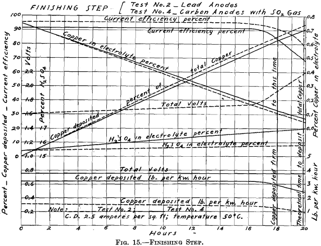
point) in Test No. 2, because the last of the copper comes down spongy and falls to the bottom of the cell. In Test No. 4, the electrolysis may be carried to the 19.85-hr. point and a good cathode produced on account of the presence of SO2 in the electrolyte. But even in Test No. 4, this point is the limit of feasible electrolysis. At the 20-hr. point, great blotches of sulphide of copper formed on the cathode. Test No. 2 may be carried to the 18th hour and produce a good, firm deposit of copper. In Test No. 2, when carried to the 18-hr. point, the results were:

Note that there is a decided saving in power by the use of sulphur dioxide gas with the carbon anodes, in the Finishing Step of Test No. 4. In Test No. 4, there is no rise of polarization as the copper contents becomes depleted, while the total voltage becomes 2.2 volts in Test No. 2.
The middle row of Fig. 13 consists of six cathodes. Counting from left to right, the first group of three (Nos. 1, 2, 3) was used in Tests Nos. 1 and 2; the second group of three (Nos. 4, 5, 6) was used in Test No. 4. Immediately below Cathode No. 2, is one of the lead anodes used in Tests Nos. 1 and 2; immediately below Cathode No. 5, is one of the carbon anodes used in Test No. 4. Cathodes Nos. 1 and 4 are from No. 1 Step of their respective tests; Cathodes Nos. 2 and 5 are from No. 2 Step of their respective tests; and Cathodes Nos. 3 and 6 are from the Finishing Step of their respective tests.
The performance in Test No. 4, in pounds of copper deposited per kilowatt-hour—between 1.82 and 3.7 lb.—is not equal to that in Test No. 3. Owing to the construction, electrodes light in weight, and resting on bus-bars, the contact resistance was abnormally high. Special precaution was taken in Test No. 3 largely to eliminate the contact resistance. Even in Test No. 3, the ohmic resistance is to that of practice as 0.108 is to 0.062. Consequently it is believed that even the showing of Test No. 3 can be bettered in practice, and with this plant on repetition.
Test No. 1 showed the performance of lead anodes when used with the step system. Test No. 2 was a modification of Test No. 1, seeking to place the operation on a more practical basis. Test No. 3 compared the performance of different kinds of insoluble anodes with and without sulphur dioxide gas. Test No. 4 showed the performance of carbon tube anodes with sulphur dioxide gas introduced into the electrolyte, when used with the step system. The operation of the Finishing Step with SO2 gas showed a remarkable saving of power as well as a better deposit of copper over that of the Finishing Step in Test No. 2 with lead anodes and no gas. (See Figs. 9, 13, and 15; Table I.)
Step System of Electrolytic Precipitation
The copper solution used in the preceding experiments was obtained by dissolving copper sulphate in water. The electrolytic plant was not supplied with copper solution obtained by leaching the ore, because the amount of ore roasted was insufficient to keep the electrolytic plant in operation for the length of time desired. Moreover, it is believed that the only additional informa-
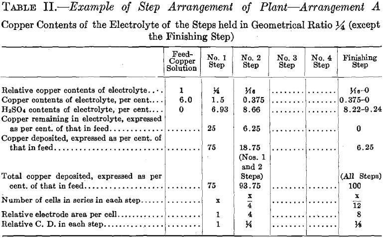
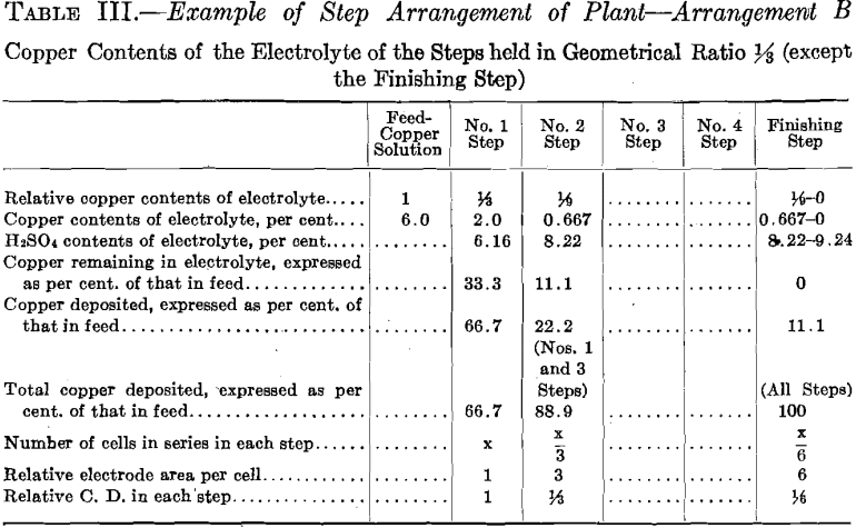
N. B.—When using carbon anodes with sulphur dioxide gas, the acid contents will be higher than given in these tables.
These tables were worked up, assuming that there was no evaporation of the electrolyte during its passage through the plant, or, what amounts to the same thing, that water was added to the different steps equal in amount to the evaporation occurring in the different steps.
tion that could have been obtained by treating copper solution resulting from ore leaching, would have been the effect of accumulation of impurities in the electrolyte. In order to determine the effect of accumulation of impurities in the electrolyte, and to inaugurate the necessary purification methods, such as chemically purifying the electrolyte or wasting a sufficient amount of barren solution, a greater amount of material than was at hand would have been required, as well as a long campaign of operation. Much information is available regarding the maintaining of the purity of solutions in a cyclic process. The analysis of the ore together with the results of the leaching tests, and the acid consumption, enables one to judge the quantity of impurities entering the leaching solution in the treatment of the ore now under discussion.
The electrolysis of the copper sulphate solution was conducted in steps. All the electrolytic cells were connected in series, while the electrodes of the individual cells were connected in parallel. Each step maintained constant the composition of the electrolyte—both in copper and acid.
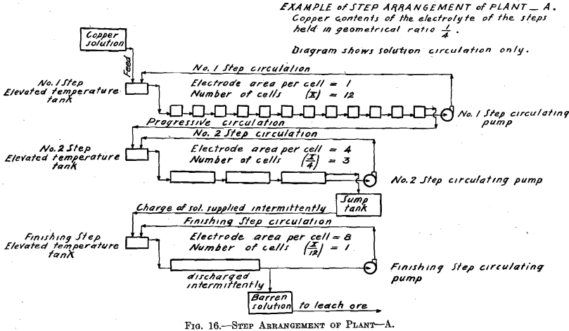
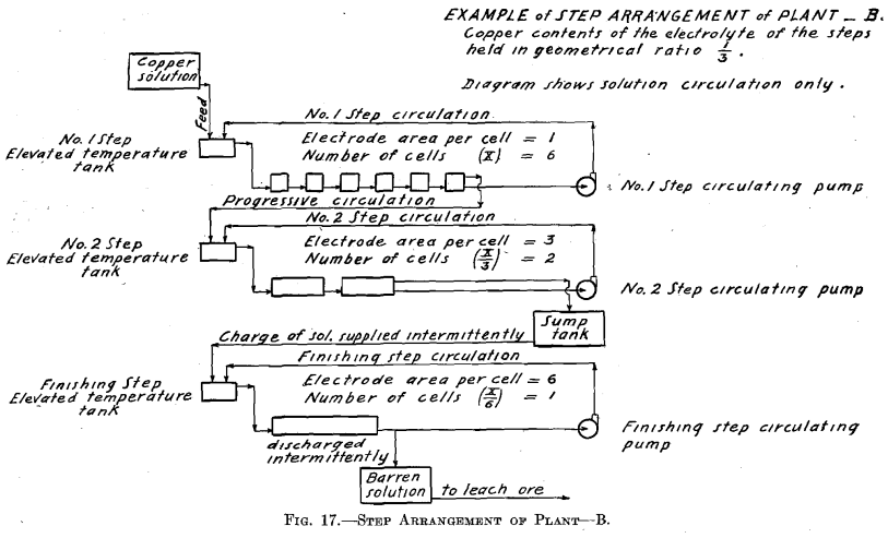
The cells comprising each step have two circulations of the electrolyte. There is one circulation, which is designated the step circulation, in which the step circulating pump draws the electrolyte from the last cell of the step, sending the electrolyte to a more elevated tank (temperature tank)
in which it may be heated (maintaining the temperature of the system constant), and from which it overflows and gravitates into the first cell of the step. The electrolyte then passes on through the series of cells in the step and finally again to the same circulating pump.
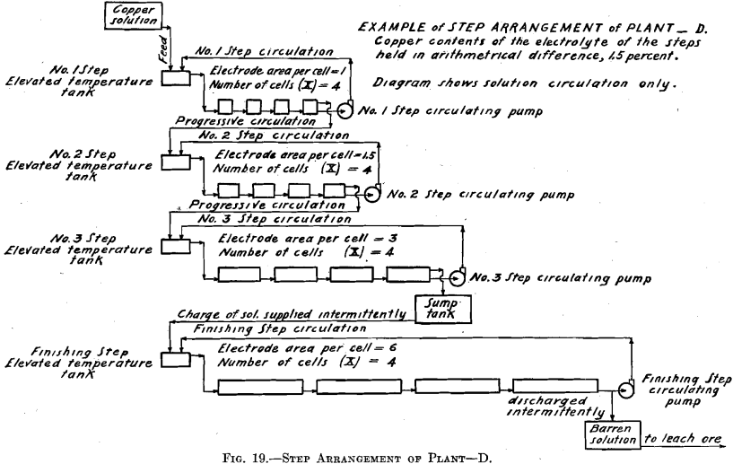
There is the other circulation, which is ordinary progressive movement of the solution through the plant. The copper solution resulting from the leaching of the ore, or otherwise obtained, is run, together with the discharge of the No. 1 Step circulating pump, into the elevated temperature tank of the No. 1 Step. Thus more solution enters the first cell of the step than is drawn away by the circulating pump, consequently an equivalent amount of solution must leave the last cell of the step by way of the overflow discharge. This overflow discharge passes on and joins the discharge of the circulating pump of No. 2 Step, and enters the elevated temperature tank connected with that step. Finally the last cell of the step preceding the Finishing Step, overflows an amount of solution equal in amount to the inflowing copper solution fed to the elevated temperature tank of the No. 1 Step.
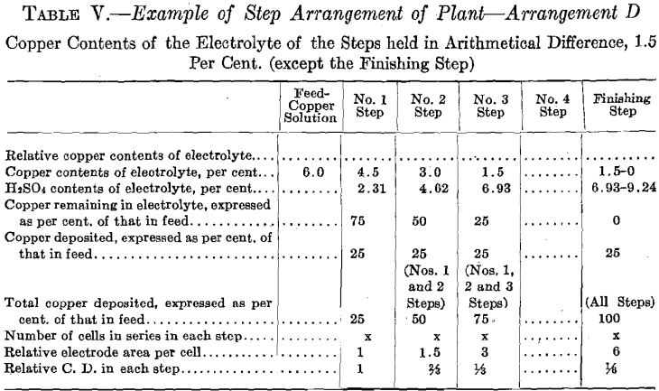
The copper contents of the solutions is maintained in geometrical ratio or in arithmetical difference from that of the copper solution fed to No. 1 Step to that of the electrolyte of the step preceding the Finishing Step.
The experimental plant was designed so that a variety of factors could be used. Let us select for a plant a solution resulting from the leaching of the ore with copper contents of 6.0 per cent, and the geometrical ratio for the copper contents of the electrolyte of the different steps. (See Table II and Fig. 16.) Then the electrolyte of No. 1 Step
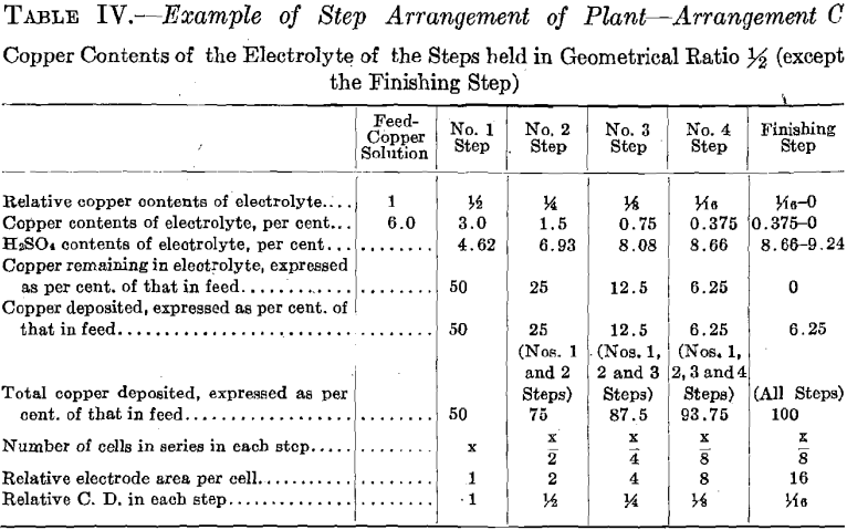
will contain 6.0/4 equals 1.5 per cent, copper, and 6.93 per cent. H2SO4. Let us further assume for No. 1 Step 12 cells in series, each with one unit of area of cathode surface. Next select the most suitable current density for this step. The copper contents of the electrolyte is the governing factor in making this selection, since it is desirable always to maintain current density proportional to copper contents of the electrolyte. The selection of current density fixes the strength of current. The copper solution is fed to this step at such a rate that the copper deposited on the cathode amounts to three-quarters of the entering copper. The electrolyte circulating in the step thus remains constant in copper contents and in acid, and the solution overflows in volume equal to that of the inflowing feed solution.
The solution fed to No. 2 Step, being the overflow of No. 1 Step, contains 1.5 per cent, copper and 6.93 per cent. H2SO4. Since the electrolyte of this step contains one-quarter as much copper as that of the preceding step, then in order to maintain the electrolyte of this step constant one-quarter as much copper must be deposited on the cathodes of this step. This is accomplished by placing one-quarter as many cells in series, namely, using three cells. These cells should each have four units of cathode area, that is, a cathode area four times as great as that employed in each cell of No. 1 Step, since in this Step (No. 2) the electrolyte contains one-fourth as much copper, which requires a current density one-fourth that of No. 1 Step to be employed.
It is seen that the solution overflowing from No. 2 Step contains but 6.25 per cent, of the original copper contents. This solution in which the acid has been regenerated may pass on and be used to leach ore. That it contains a small amount of copper is no detriment since this copper will return in the enriched solution and will not be lost.
In case it should be desired to extract the copper to the last trace, one more step—a finishing step—may be added to the plant. This step would be supplied intermittently with a charge of solution from the sump tank,
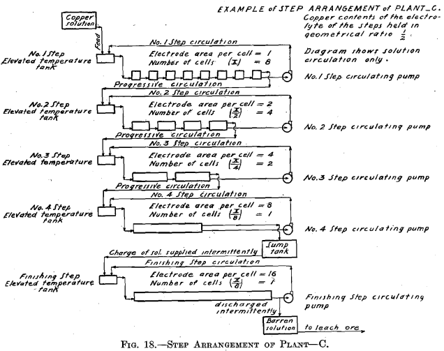
where the solution overflowing from No. 2 Step has collected. This charge of solution would be circulated in the Finishing Step by a circulating pump in the same manner as in the preceding step but with neither feed nor overflow, until all of the copper contents is deposited on the cathode. The solution, barren in copper, would be withdrawn from the system, after which a new charge would be supplied.
The number of cells in series in the Finishing Step would be one-third the number used in No. 2 Step. Then this step must operate continually to deposit all the copper sent to it by the overflow of No. 2 Step, since the amount of copper contained in the overflow solution of No. 2 Step is one-third the amount deposited in that step. The cells of the Finishing Step should each have (in this example there is but one cell) eight units of cathode area, that is, twice the cathode area and one-half the current density as that employed in each cell of No. 2 Step, as in this step (Finishing Step) the electrolyte has on an average one-half the copper strength.
Even when the Finishing Step is employed, it may be desirable to stop the electrolysis somewhat short of complete extraction. (This matter is discussed in connection with Tests Nos. 2 and 4.)
In order to obtain the figures given above, it is necessary to compensate for evaporation, which at the temperature employed (50° C.) and with the large surface of solution exposed is considerable. In Test No. 1, evaporation was compensated for by the addition of water to the temperature tank of each step, equal in amount to that of the evaporation. Thereby was demonstrated the feasibility of maintaining the composition of the electrolyte constant, both in copper and acid, during the electrolysis, and with copper contents of the electrolyte of the different steps in the above-described ratios (4:1)
In Tests Nos. 2 and 4 the plan of operation was slightly modified from that followed out in Test No. 1 in order to somewhat simplify the operations. To the temperature tank of No. 1 Step was fed a more dilute copper solution, which amounted to the original volume of the 6.0 per cent, copper solution plus the required amount of water to compensate for evaporation of No. 1 Step. Consequently No. 1 Step oper-
ated in every way exactly as it did in Test No. 1, thus maintaining the composition of its electrolyte the same and causing an overflow equal in amount and composition to that in Test No. 1. This calling for a more dilute copper feed solution might be an advantage in practice, as it might be easier to secure than the one of higher copper contents. Further dilution of the copper solution fed to No. 1 Step, to compensate for evaporation in No. 2 Step, is not permissible as it would derange the constant conditions desirable to be maintained in that step. Moreover, for simplicity of operation, water was not added to No. 2 Step to compensate for evaporation, consequently the copper contents of the electrolyte of No. 2 Step differed from the original geometrical ratio. A higher value of both the copper and the acid contents obtained. Such higher values of both copper and acid, however, remained constant. The higher copper value would permit of a somewhat smaller electrode surface and higher current density per cell than was called for in Test No. 1.
The ideal of the copper hydrometallurgist is to secure, in the hydro-electrolytic extraction of copper from its ores with insoluble anodes, conditions comparable with those which obtain in the electrolytic refining of copper with soluble anode. By means of the step system it is believed that these conditions are more nearly approached than they have been heretofore. The desirable conditions are: (a) Constant composition of electrolyte with current density adjusted to suit composition; (b) small power consumption.
The step system arrangement of the electrolytic cells accomplishes “a” and also permits the electrolyte to be circulated at any rate desired as in electrolytic refining of copper. A rapid rate of circulation in the individual cells which is made possible by the step system, together with the adjusting of the current density proportionate to the copper contents (which is held constant in each step), makes possible the securing of high current efficiency.
As most copper ores contain sulphides, they should be roasted prior to leaching. Sulphur dioxide gas is evolved. In such cases it may be desirable to pass this gas through the electrolytic cells, utilizing it as a depolarizer and at the same time producing additional sulphuric acid for the leaching. Ordinarily in leaching copper ores, the solution takes up some iron from the ore. Were no sulphur dioxide gas introduced into the cell, the ferrous sulphate would become oxidized to ferric sulphate at the anode. The ferric sulphate formed would be carried by circulation of the electrolyte to the cathode where it would dissolve some of the deposited copper, again becoming ferrous sulphate, after which the cycle would be repeated. Current efficiency would thus be decreased. But the sulphur dioxide gas when employed with a suitable insoluble anode, besides maintaining a high current efficiency, is beneficial in reducing the power consumption to a point more comparable with that consumed in the electrolytic refining of copper with soluble anode. (See Figs. 14 and 15.)
Increased areas of electrodes to give reduced current density for corresponding depletion in copper contents of the solution in the process of electrolysis have been used heretofore. In these processes, however, there is but one circulation of the electrolyte, namely, that through the plant progressively; the solution becomes depleted of the copper during its passage. Such a circulation would necessarily be slow and insufficient for securing the best results. Moreover, the electrolyte, due to the slow progress through the cells, would vary in composition in different parts. So, although in the ordinary processes the aim is to maintain the current density proportional to the copper contents, it has not really been accomplished.
The step arrangement of the plant is such that:
- Rapid circulation is maintained by the step circulating system.
- The composition of electrolyte remains absolutely constant in each step of the plant.
- The current density is held strictly proportional to the copper contents of the electrolyte.
Copper Electrolysis Process Explained
It was desired to select an Arizona problem, so the treatment of a porphyry copper ore seemed to be one of the most important. This kind of ore when treated for the extraction of its copper by mechanical concentration and smelting, the methods most generally employed, yields 66 per cent, or less of its copper.
In these experiments, therefore, the aim was to determine a better method of treatment. The method selected for investigation was one in which metallurgists are at present doing much experimenting in the hope of demonstrating the superiority of leaching and electrolytic precipitation over earlier practice, namely: 1, Oxidizing roast; 2, leaching with dilute sulphuric acid; 3, electrolytic precipitation of the dissolved copper.
While it was planned to carry on a complete systematic test of the ore, thereby enabling one to determine the suitability of this ore to the hydro-electrolytic treatment, special stress was laid on roasting and on electrolytic precipitation using sulphur dioxide to lessen the consumption of power and to produce additional sulphuric acid.
It has been demonstrated in these experiments that it is feasible successfully to roast the ore, so that when leached with hot dilute sulphuric acid, the entire copper contents may be obtained in solution.
Some of the practical engineers say that they secure but little beneficial reduction in power consumption when using sulphur dioxide gas as a depolarizer. Tossizza says, “I have thought to use insoluble anodes kept in contact with sulphurous acid, and thus to utilize the known depolarization properties of the said sulphurous acid. These anodes can be made of carbon, and in this case the sulphurous acid can be introduced outside the anode or in the interior thereof;” “One can thus obtain a very beautiful deposit of pure electrolytic copper with a sufficient intensity at a voltage of about six-tenths of a volt.” The experiments reported under Tests Nos. 3 and 4 corroborate Tossizza’s statement in that the method of introducing the sulphur dioxide into the electrolyte is unimportant, provided only that it be introduced in sufficient quantity to keep the electrolyte saturated.
Regarding the saving of power (depolarization), these experiments show depolarization by the use of sulphur dioxide only when used in connection with carbon anodes, while Tossizza, although specifically suggesting a carbon anode, intimates that the same may be obtained with other insoluble anodes. Tossizza does not state the current density at which he was operating when depositing copper with the extremely low voltage of six-tenths of a volt, although “with a sufficient intensity” might mean commercial current density. Experiment Test No. 3 shows likewise that copper deposits continuously at six-tenths of a volt when current density equals 5.8 amperes per square foot, depositing 4 lb. of copper per kilowatt-hour. (See Fig. 14.) It is to be noted that although beneficial depolarization and consequent saving of power is secured at all current densities, when SO2 is introduced into the electrolyte, it is relatively not the same in amount but decreases as the current density increases.
It is to be hoped that future experiments will demonstrate how to secure the same beneficial depolarization with sulphur dioxide when electrolyzing with high current densities. Likewise whether, and how, beneficial depolarization by sulphur dioxide may be secured with other kinds and types of insoluble anodes.
When it is desired to extract the copper from the electrolyte down to a small trace, sulphur dioxide is very beneficial, not only in reducing the power consumption but in causing the copper to deposit more firmly on the cathode, which when sulphur dioxide gas is not used forms as a spongy deposit toward the last of the electrolysis. On attempting to extract the last trace of copper from the electrolyte, sulphide of copper forms on the cathode.
Regarding the lead anodes, there is no depolarization when used with or without sulphur dioxide gas. There was no loss in their weight during the test.
When starting out on this line of investigation, it was found necessary to design and construct a complete plant on a miniature scale. In doing this, a novel idea appeared—the step arrangement—which greatly facilitated the work in all stages of the process, especially in the finishing step where the copper was extracted down to a trace with the production of a good firm cathode, when sulphur dioxide gas was used.
Test No. 1 demonstrates, when using the step system, the feasibility of depositing copper continuously from the electrolyte, while at the same time the copper contents of said electrolyte remains undiminished: A plant composed of several steps of such cells may be operated so that a liquor strong in copper flows into the upper step of the plant continuously from the leaching vats at such a rate that a liquor depleted of its copper, in which the acid solvent has been regenerated, outflows from the plant continuously to the leaching plant. The advantages of a step arrangement of plant are apparent in that the electrolysis is conducted under constant invariable conditions in each cell of the respective steps, as well as in every part of the cell. The cathode area of a step may easily be adjusted so that the most desirable current density is secured (as determined by experience in operating). It is to be noted in step arrangement of plant, the electrolyte may be circulated in any of the steps at any desired rate. This has been shown to be beneficial in promoting high current, efficiency.
The experiments demonstrate that the porphyry ore, when treated by a hydro-electrolytic process, will yield its entire copper contents as a good grade of cathode copper. It is therefore hoped that by using a hydro-electrolytic method, lower-grade copper porphyry deposits may be worked than formerly could be worked by methods of concentration followed by smelting.
Epitome
- The most suitable temperature for roasting the Arizona porphyry copper ore, containing sulphides, in order to render it amenable to acid leaching methods, is between 600° C. and 725° C. The more finely ground the material the shorter the time required for the roasting so as to produce the maximum amount of soluble copper: materials which will pass through a 20-mesh screen and remain on 80 mesh require about 2 hr. roasting at 600° C. to 725° C.; and when ground to pass through an 80-mesh screen the time required is about hr. If the roasting is concluded at temperatures above 800° C., the oxidized copper is converted into a compound which is insoluble in dilute sulphuric acid. The longer the roasting is conducted above 800° C., the greater the amount of insoluble copper produced.
- A heated solution is necessary to leach efficiently the copper from the roasted material. A 10 per cent. H2SO4 solution at 100° C. leached out, in from 3 to 6 hr., all the copper from all roasted materials (through 40 on 80 mesh, through 80 mesh, whole through 20 mesh), except material through 20 on 40 mesh, in which case the extraction was not so high.
- The nature of the anode is an important factor in securing depolarization by sulphur dioxide gas.
- Depolarization with consequent saving in power is accomplished when using sulphur dioxide gas with a carbon anode, while there is no depolarization with a lead anode.
- The depolarization by sulphur dioxide gas, even with carbon anodes, does not reach the theoretical amount, being between 45 and 65 per cent.
- The amount of depolarization effected by sulphur dioxide gas when used with carbon anodes varies with the current density, being a maximum at low current density.
- The method of introducing the sulphur dioxide gas into the cell is unimportant. All that is necessary is that it be introduced in some way, and in such quantity that the electrolyte is saturated with the gas, so that there is some escaping by bubbling at the surface.
- A smoother deposit of copper forms when using sulphur dioxide gas as a depolarizer than when not using it.
- In the electrolysis of an acid solution of copper sulphate, when sulphur dioxide is not supplied to the cell and when one is endeavoring to carry electrolysis to the point of complete extraction, a soft spongy deposit begins to form on the cathode before the complete extraction of the copper is effected. There is also a considerable rise in polarization when the copper contents of the electrolyte becomes low.
- In the electrolysis of an acid solution of copper sulphate, when sulphur dioxide is supplied to the cell, the copper contents of the electrolyte may be reduced to a very small trace with the formation of a good, firm cathode, without rise in polarization toward the end. Current density and energy efficiency remain high to the end. It is only when prolonging the operation beyond the time when but a small trace of copper remains that sulphide of copper forms as a thin coating on the cathode.
- Lead anodes do not peroxidize or deteriorate appreciably when used with or without the introduction of sulphur dioxide into the electrolyte.
- A novel idea—step arrangement of process—makes feasible the depositing of copper continuously, while the copper contents of said electrolyte in the respective steps remains constant. A plant composed of several steps of such cells may be operated so that a liquor strong in copper flows to the plant continuously, and the liquor which outflows from the plant is depleted of its copper.
- The circulation of the electrolyte by the step arrangement increases the current efficiency. Such rapid circulation is not possible in plants as ordinarily arranged.
