Table of Contents
The preparation of aluminum by molten salt electrolysis of AlCl3 was undertaken as part of the Bureau of Mines overall research program to develop methods for the utilization of domestic low-grade raw materials, de Beauchamp and Thomas and others summarized the preparation and manufacture of anhydrous AlCl3 from a variety of aluminiferous materials: aluminas, bauxites, kaolins, shales, aluminum silicates, and other clays and rocks.
Earlier efforts on the electrolytic preparation of aluminum from AlCl3 were summarized by Good and coworkers in their research report on small-scale, batch AlCl3 reduction tests. A two-compartment cell for the reduction of AlCl3 was constructed and operated to determine feasibility of continuous aluminum production by this method. The cell was designed to accommodate feeding AlCl3 as a vapor. Successful operation of this cell led to the present study whose objective was to develop a simple cell design for continuous AlCl3 reduction using a particulate AlCl3 feed and to determine suitability of cell construction materials, feed methods; product removal and operational parameters for the cell. This investigation was of 6 months’ duration.
There are several potential advantages for the production of aluminum from AlCl3 rather than from Al2O3 in a fluoride system. A lower operating temperature, 700° to 750° C versus 960° to 1,000° C in a Hall Heroult cell, should lower energy requirements. The electrolyte is less corrosive and coupled with lower temperature operation, promotes longer cell life and increases the variety of suitable cell construction materials. NaCl-KCl salts used in the electrolyte are cheaper than the component salts used in the present process. Reduction of AlCl3, instead of Al2O3, precludes anode carbon consumption and enables greater productivity from smaller, more compact cells, since higher anode current densities are possible with essentially nonconsumable anodes. Metal of higher purity should be produced from chloride systems, since impurities contributed by carbon of both the consumable anodes and the pot linings would be eliminated. A broader operating range of aluminum concentration is possible with aluminum chloride in a chloride electrolyte than with alumina in a fluoride electrolyte. Further, aluminum chloride concentration can be maintained at a selected level in the chloride electrolyte avoiding cyclic concentrations that result in periodic anode effect and accompanying lower efficiencies in the Hall-Heroult cells.. Large quantities of gases and particulate matter which contribute to air and ground pollution are evolved from Hall-Heroult cells. The AlCl3 cells utilize a closed system and should minimize pollution problems.
Experimental Equipment
Cell Assembly
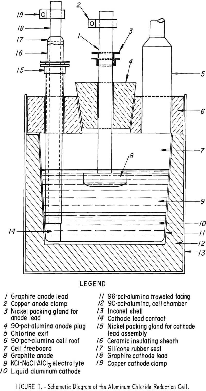
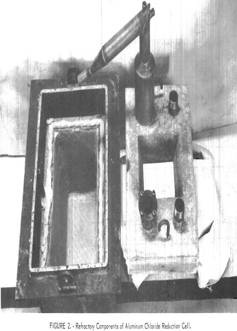
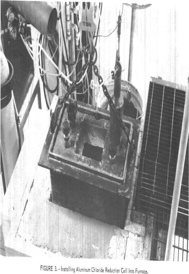
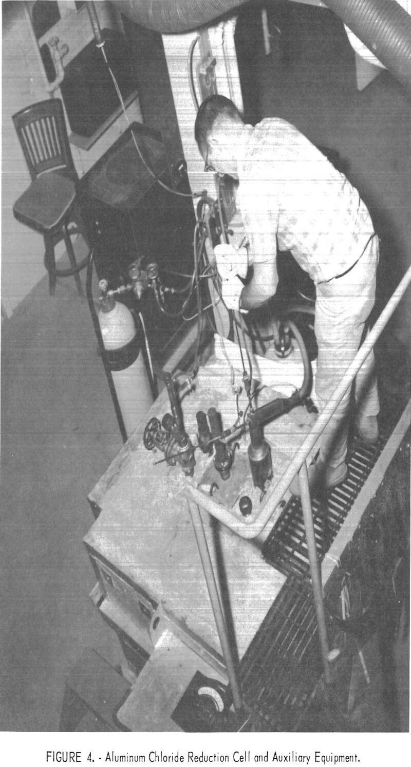
A sectional drawing of the AlCl3 reduction cell used in this investigation is shown in figure 1. Figures 2 to 4 show the cell at successive stages of construction.
A rectangular shell of ½-inch Inconel, 23-¾ inches long by 15 inches wide by 22 inches deep, was lined on the floor and sides with a 90-percent alumina phosphate-bonding, plastic refractory mixture applied by ramming with a pneumatic hammer. The formed refractory cell chamber was 12-5/8 inches deep, 8 inches wide by 16-¾ inches long at the floor level, and 10 inches wide by 18-¾ inches long at the top. The floor was 3-½ inches thick and the side- walls tapered from 3 to 2 inches. After air drying the cell interior, it was
faced with a 1/8- to ½-inch-thick layer of a 96-percent-alumina phosphate-bonding mixture of troweling consistency, which was also air-dried. The refractory composite was then cured as specified by the manufacturer to fully develop its chemical bonding.
A 4-inch-thick roof slab was formed of the 90-percent-alumina refractory mixture. It was placed on top of the cell refractory after drying and curing and sealed to it with the troweling mix. The roof slab had four embedded access ports of nickel tubing or pipe, one at each corner of the slab, which were anchored by ramming the refractory through perforated flanges attached to the nickel components as the slab was formed. The four ports and their functions were:
- A 4-inch tube reducing to 1 inch for exhausting the chlorine to a recovery system.
- A 1-½-inch capped pipe for siphon-tapping aluminum and for taking electrolyte and cathode samples.
- A 2-½-inch pipe with a packing gland for supporting 2- to 2-1/8- inch-diameter mullite or alumina tubes which enclosed and insulated a 1-5/8- inch -diameter graphite rod cathode connection to the molten aluminum.
- A 1-½-inch pipe fitted with a 1-½-inch stainless steel gate valve through which (a) granular AlCl3 was fed to the cell, (b) cathode and electrolyte depth measurements were taken, (c) internal temperatures were measured, and (d) nitrogen gas purge was supplied to the cell.
The roof slab contained a central opening 8-½ by 8-½ inches tapering to 6-½ by 6-½ inches on the bottom side, into which was fitted a matching 5-inch-thick, rammed-anode assembly plug. The plug had a centered access opening of 2-inch nickel tubing with a nickel packing gland for supporting and sealing a 1-½-inch-diameter graphite anode connector rod. The lower end of the connector was threaded for attachment to drilled-and-tapped crowned-faced anodes. Three anodes, fabricated from 2-inch-thick graphite stock, were used. They were a 6-inch disk of 28 square inches area and two rectangular shapes, similar in proportions to the molten cathode, of 34 and 50 square inches area. These anodes provided cathode-to-anode area ratios of approximately 5 to 1, 4-½ to 1, and 3 to 1, respectively. All anodes and anode and cathode rod connectors were machined from National Carbon CS-grade graphite. Stranded copper cables and copper clamps provided direct current connections to the graphite electrode leads from a 12-volt, 200-ampere selenium rectifier.
Seals were made between the cell lid and anode plug with either troweling mix or ordinary oil-base caulking compound. Graphite-blue asbestos packing was used in the packing glands to seal around anode lead and cathode lead sheaths. Self-vulcanizing, high-temperature silicone rubber was used to form an external seal between the cathode lead and its mullite or alumina enclosure tube. Small leaks during operation were closed by local application of moisture which hydrolyzed the AlCl3 content of escaping vapors.
The cell was installed in a furnace equipped with Globar elements.. The temperature controller for the furnace was connected to a type K thermocouple within a nickel-protecting tube embedded in the refractory cell sidewall , Lightweight cast insulation was installed over the furnace and cell.
The AlCl3 cell feed was purchased from a commercial supplier and was received in 50-pound drums. A stainless steely conical lid; terminating in a 2-inch opening, was built to fit the drums. Two-inch-diameter flexible vinyl chloride tubing was used to connect the lid to the feed port of the cell- The feeding assembly is depicted in figure 5. The feed container was supported on platform scales to measure individual and collective additions of AlCl3.
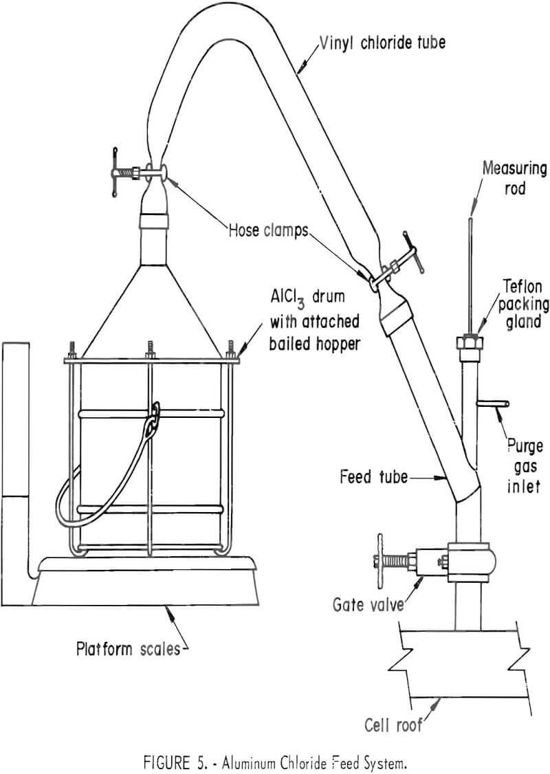
Metal cathode and electrolyte depth measurements were made by inserting a ¼-inch nickel rod to the floor of the cell through a Teflon packing from an entry above the feed valve. Local heating of the portion of rod contacting molten aluminum prevented freezing of salt on that portion during withdrawal. After removal, the metal depth was represented by bare rod and the electrolyte depth, by a thin coating of electrolyte adhering to the rod.
Chlorine Recovery System
The evolved chlorine from the electrolytic reduction of AlCl3 was collected by absorption in a caustic solution. Chlorine was exhausted from the cell along with purging nitrogen and some sublimate from the electrolyte through 1-inch-diameter flexible vinyl chloride tubing to an empty 5-gallon Pyrex bottle where the sublimates were collected. The cell gases were then ducted through 1-inch tubing and ½-inch rigid polyvinyl chloride pipe into 10-percent sodium hydroxide solutions contained in one of two 6-gallon polyethylene gas scrubbers. The gas scrubbers were alternated for separate electrolytic tests. The exit from the working scrubber was connected to an aspirator that maintained the cell under a negative pressure of about 1-½ inches of water.
Experimental Procedures and Results
Cell Operation
A three-component electrolyte (KCl-NaCl-AlCl3) was used in the investigation. An equimolar mixture of KCl and NaCl was the solvent portion of the electrolyte. AlCl3, the solute, was electrolytically reduced to metal which deposited on a liquid aluminum cathode. Chlorine evolved at the anode was continuously exhausted from the cell. AlCl3 additions were made to the electrolyte to compensate for its reduction. All salts were anhydrous technical grade.
Forty pounds of aluminum (alloy 1100, minimum 99.0 percent Al) were placed in the cell with a covering of KCl-NaCl mixture. The cell was heated to 700° C to melt both metal and salt, and the balance of the KCl-NaCl mixture, which totaled 75 pounds, was added in increments. The liquid aluminum neither wet nor penetrated the refractory. It formed a pool on the floor of the cell 3-3/16 inches deep and provided a cathode surface of 146 square inches. A total of 34-½ pounds of the charged KCl-NaCl mixture penetrated the refractory walls leaving a molten salt pool 4-¾ inches deep over the liquid aluminum.
The addition of 10 pounds of AlCl3 completed the starting electrolyte. Eight and three-tenths pounds were retained in the working electrolyte, and the balance was dissolved by KCl-NaCl within the refractory. The electrical connection to the cathode was made by immersing the graphite lead 2 inches into the molten cathode. The anode assembly was installed in the cell roof with the lower anode surface positioned in the electrolyte 3 inches above the initial cathode surface. Electrolysis at 100 amperes was performed for 1,400 ampere-hours to condition the electrolyte and to saturate the cell and scrubber system with chlorine.
At the start of the investigation, reductions of 500 to 1,600 ampere hours were performed during day shifts with the cell temperature maintained continuously. Each day’s reduction constituted a test. Bath measurements were made, and electrolyte samples were taken at the start and conclusion of each test. Electrolyte samples were extracted by sucking electrolyte into Pyrex glass tubes inserted through the tapping port. Similarly, Vycor tubes were used to extract metal cathode samples on a weekly basis. AlCl3 replenishment additions were made, and chlorine recovery scrubbers exchanged after each test. Following each test, the resulting scrubber solution was diluted with water to 20 liters. Samples were then analyzed for total chloride by Mohr’s method following treatment with H2O2. Electrolyte samples were analyzed for aluminum content by atomic absorption spectrometry.
Anode current efficiencies of tests were calculated from produced chlorine. These efficiencies were used to evaluate cell performance, as they were considered to provide a more precise short-term evaluation basis. Deviations of cathode from anode current efficiencies essentially result from reaction of chlorine with oxychlorides in the electrolyte or with any part of the cell structure, Electrowinning from alkali chlorides should not cause appreciable deviation of current efficiencies.
The early tests exhibited high cathode contact resistance at the start of each electrolysis. The initial voltage required to obtain desired cell current was 1.5 to 3.5 volts over steady operating voltage which was usually reached after 20 to 50 minutes of electrolysis. The high initial resistances were attributed to reaction between alkali metal in the cathode and the graphite which resulted in swelling and exfoliation of the contact surface. Electrolysis lowered the contact resistance, as the damaged surface of the contact formed a sludge which accumulated in the electrolyte just above the cathode surface. This cyclic process continued until all the graphite in contact with the cathode metal had eroded away, and the current shorted through the electrolyte. The first two cathode contacts lasted a total of 24,500 ampere-hours before such failure.
The life of the graphite cathode leads was extended by operating the cell continuously. During unattended periods electrolysis was performed at 25 amperes instead of being stopped. This continuous electrolysis eliminated the high voltages and slowed contact degradation. The third contact lasted 62,000 ampere-hours before failure.
Titanium diboride was selected for trial as a cathode contact material because of its conductivity and compatibility with molten aluminum. A 6-inch- long, 1-inch-diameter high-density rod of pressed-and-sintered TiB2 replaced the fifth graphite contact. The rod was inserted into and mechanically suspended from an end-bored 1-¾-inch graphite rod. This assembly was installed in the cell, as were the previous graphite leads, within an insulating sleeve. The TiB2 cathode connection was used for the balance of the investigation, 73,440 ampere-hours of continuous electrolysis, with improved results. It lowered the cell voltage about 0.5 volt at 200 amperes. This eliminated voltage fluctuations resulting from changes in contact resistance and prevented the accumulation in the electrolyte of carbon sludge. The use of the TiB2 contact did not significantly improve current efficiency.
With the change to continuous, rather than intermittent, electrolysis, bath sampling and measurements and chlorine scrubber changeovers were made to coincide with the conclusion of one test and the beginning of another. AlCl3 replenishments to the electrolyte were made at regular intervals with no interruption of electrolysis.
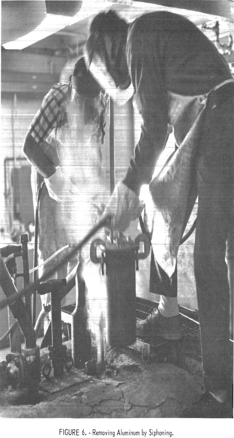
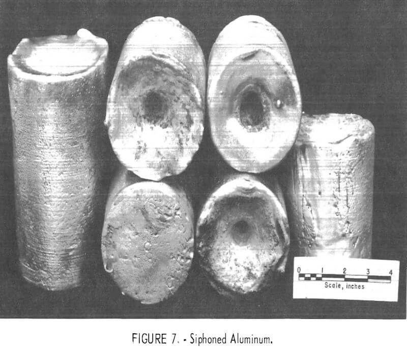
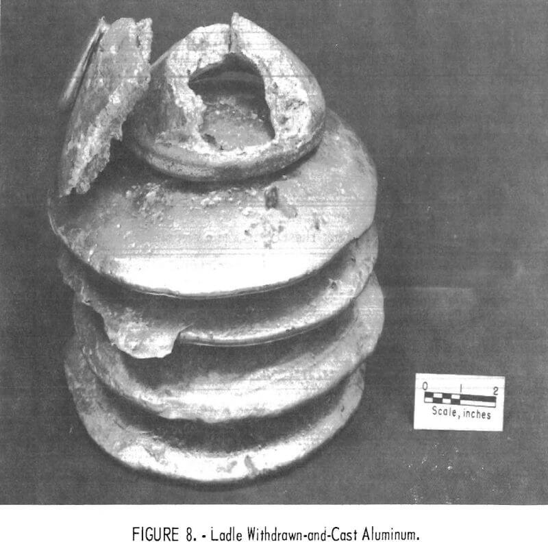
Aluminum metal was usually removed from the accumulating liquid cathode by tapping with a portable vacuum siphon, assembly which was an adaptation of equipment used in a preceding investigation. This operation is shown in figure 6. Metal removed by siphoning into a graphite crucible is shown in figure 7. On occasions of anode plug removal for anode exchange, aluminum was removed by ladling through the opening in the cell roof. Metal ladled and cast in an iron crucible is shown in figure 8.
While the cell was open for anode exchange, sludge was removed from the cell floor and from between the cathode and electrolyte. The sludge from the floor was essentially alumina grains from the cell lining. The sludge between the metal and electrolyte was carbonaceous material from the degradation of graphite cathode leads. Both were removed with fine-toothed skimming rakes of stainless steel construction.
Investigation of Operating Parameters
Current Density
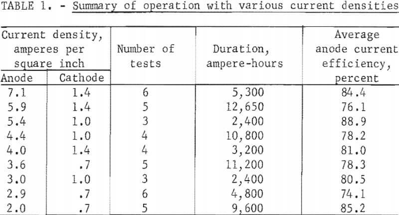
Three anode configurations were tested to study current density effects. A rectangular anode of 50-square-inch surface replaced the original circular anode of 28-square-inch surface after 6,700 ampere-hours of electrolysis. A rectangular anode of 34 square inches of anode surface was installed after 82,600 ampere-hours and was in use at the conclusion of the investigation after another 89,000 ampere-hours of electrolysis. These anodes and a current operating range of 100 to 200 amperes resulted in anode current densities of 2.0 to 7.1 amperes per square inch. With the same current range, the cathode current densities were 0.7 to 1.4 amperes per square inch.
Table 1 summarizes current efficiencies at various current densities. The table includes results of tests, widely distributed throughout the investigation, in which anode-cathode separation was 2-½ to 3-½ inches and excludes tests preceding or following the opening of the cell for anode or cathode lead exchange. Other operating conditions varied within wide limits and masked any trends. These variations include the aluminum content of the electrolyte, quality of graphite cathode contact, and the use of TiB2 cathode contact. The results do not dispute earlier findings that current efficiency is improved by increased current density. Efficiencies obtained when the cell was idling at 25 amperes, 0.5 to 1.0 ampere per square inch on the anode, were inferior to those from investigative tests. Typically, reductions at 100 to 200 amperes resulted in anode efficiencies of 75 to 88 percent, while idling reductions at 25 amperes resulted in efficiencies of 30 to 50 per-cent. The maximum anode current density with this cell was not determined.
Temperature
The melting point of the equimolar KCl-NaCl mixture, 658° C, and the melting point of aluminum, 659.7° C, established the lower temperature limit for operation of the AlCl3 reduction cell. Temperature was controlled to maintain the aluminum cathode between 700° and 800° C, because higher temperature promoted AlCl3 vapor losses from the electrolyte. Temperature was periodically surveyed within the cell at 1-inch depth increments from hearth to roof with an Inconel-sheathed type K thermocouple inserted through the feed port. The electrolyte temperature was 50° C less than the cathode temperature when electrolysing up to 25 amperes, and 35° C less when electrolyzing at 100 to 200 amperes. There was no discernible effect on efficiency with temperature variation within the range employed.
Grothe and Piel, in their investigation of the system KCl-NaCl-AlCl3, between 670° and 730° C, observed that an increasing NaCl content causes a separation from the melt of a doughy-solid, NaCl-rich phase. This separation occurred in the reduction cell where it resulted from sublimation losses; cell sublimates were essentially KCl-AlCl3. Occasional doughy crusts over the electrolyte hindered chlorine evolution and gave low efficiencies. These occurrences were corrected by breaking the crusts and temporarily increasing temperature.
Furnace power demands to maintain cathode temperature without electrolysis averaged 7.34 kilowatts. Input of 1 kilowatt of direct current for electrolysis reduced the required furnace power by 6 to 8 percent.
Electrolyte Composition
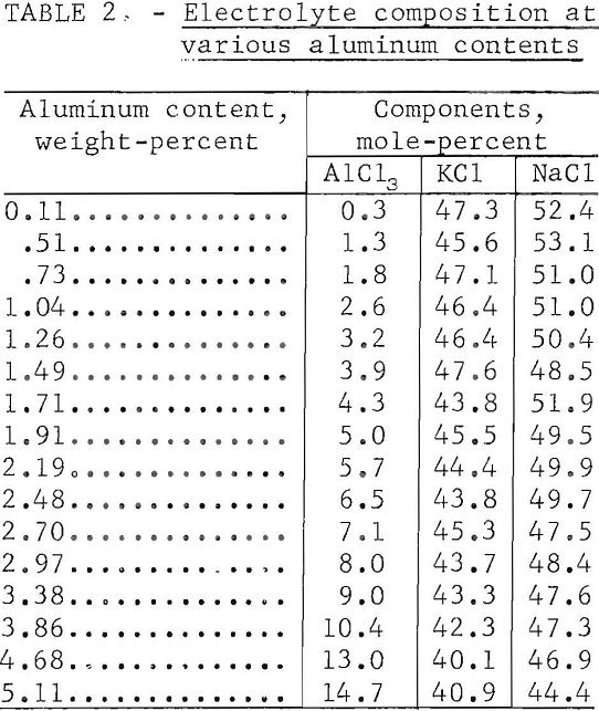
Electrolyses were made with electrolytes containing 0.1 to 5.0 percent aluminum (0.5 to 25 percent AlCl3). No consistent or reproducible effect on efficiency resulted from variations in aluminum content; although best operation with fewer voltage fluctuations was observed when the concentration was maintained between 1.5 and 3.5 percent aluminum (7.5 to 17.5 percent AlCl3). Anode effect, an abrupt voltage increase coincident with electrowinning from the alkali chlorides, occurred when the electrolyte was depleted to 0.25 percent aluminum (1.25 percent AlCl3).
Table 2 presents typical electrolyte compositions related to varying aluminum contents. These compositions are listed in order of increasing aluminum content rather than in chronological order. All compositions demonstrate depletion of KCl, resulting from sublimation of KCl-AlCl3, from the original 1- to -1 molar KCl-NaCl proportions. The equimolar KCl and NaCl composition used in preceding investigations was selected for reasons of its stability, fluidity, and the reduced volatility of AlCl3 dissolved in it.
Cell Atmosphere
The cell was ordinarily operated with a flow of ¼ cfh nitrogen into it to reduce the effects on cell pressure of any abrupt changes in chlorine evolution. A negative pressure of 1-½ inches of water was usually maintained within the cell to exhaust chlorine and nitrogen to the scrubbers. In individual reductions, negative pressures up to 6 inches of water were maintained with no apparent improvement in cell efficiency or operation. Increasing the nitrogen purge up to 2 cfh improved efficiency slightly.
Metal Quality During Operation
The aluminum charged to the cell for the initial molten cathode, contained (in percent) 0.60 Fe, 0.21 Si, 0.011 Mn, 0.06 Cu, and 0.004 Ni. At the conclusion of the investigation the cathode metal contained (in percent) 0.53 Fe, 0.13 Si, 0.05 Mn, 0.02 Cu, and 0.90 Ni. Figure 9 depicts the changes in aluminum quality during the investigation. It is apparent that product purity, with respect to iron, silicon, and copper contamination, improved with
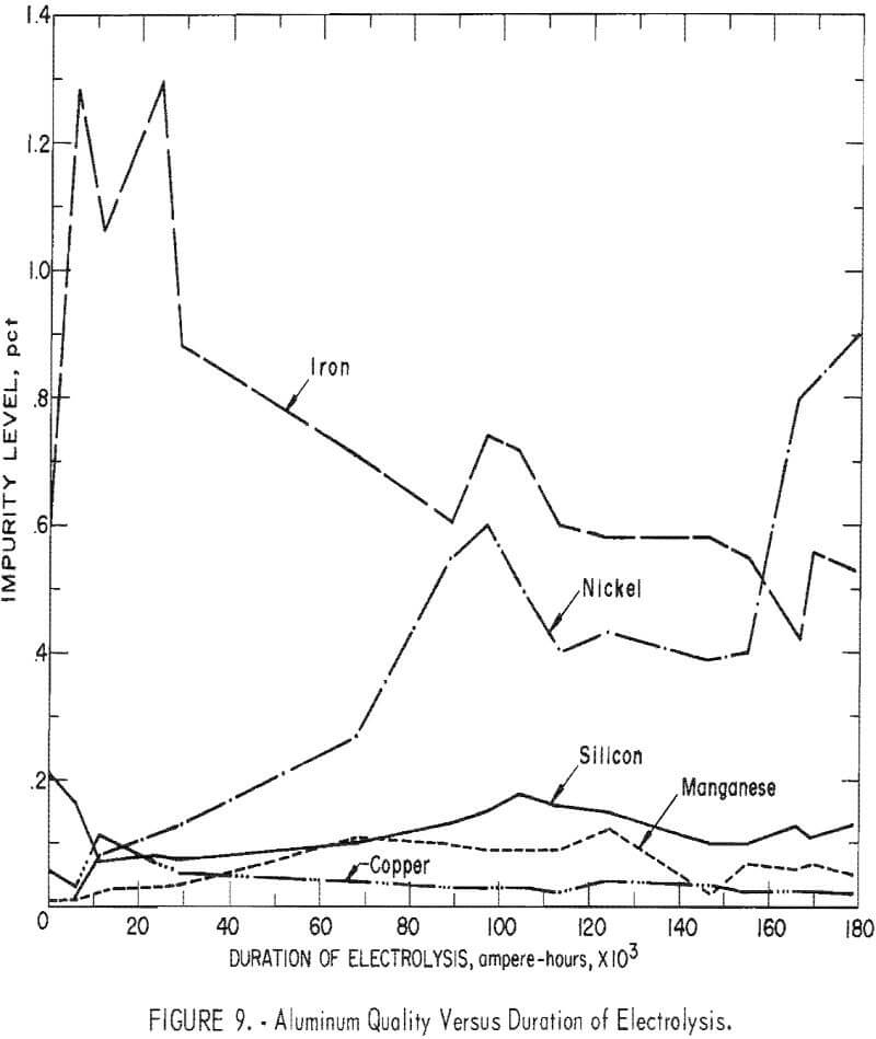
length of operation. There was an initial increase of iron in the products which was attributed to the removal of the iron impurity from the ceramic cell structure. The nickel increase was derived from the shell, as well as exposure of the cathode to the implements used, which were as follow: tapping ladles, thermocouple probes, sludge rakes, and measuring rods. While the nickel increase was substantial, it was the result of operation in an experimental cell and would not occur in a larger cell.
The commercial AlCl3 cell feed contained as impurities (in percent) 0.04 Fe, 0.01 Mn, 0.007 Ni, 0.002 Si, and 0.001 Cu. Retention of these impurities in the produced aluminum would result in a product containing (in percent) 0.2 Fe, 0.05 Mn, 0.03 Ni, 0.01 Si, and 0.005 Cu. As seen in figure 9, the impurities in the aluminum, except for nickel, were approaching these values. By using purified AlCl3 feed material, it appears probable that high-purity aluminum (99.8 to 99.95 percent) could be routinely produced by this process.
There was no evidence of accumulation of aluminum oxychlorides in the electrolyte during the investigation. Aluminum chloride hydrolysis products introduced to the electrolyte during feeding or by opening the cell for measurements, sampling, or tapping were apparently rechlorinated at the anode surface.
Anode-Cathode Distance
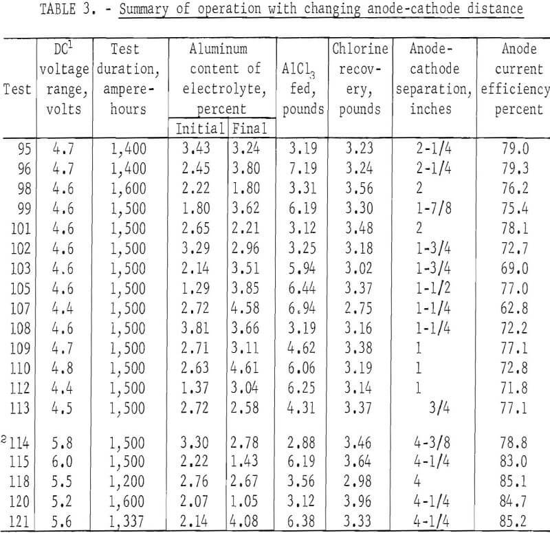
A series of reductions, performed to determine the effects of anode-cathode spacing on electrolysis, is summarized in table 3. This series consisted of 19 tests at 200 amperes for a duration of 1,400 to 1,600 ampere-hours each, using the TiB2 cathode contact and a 34-square-inch rectangular anode. Furnace power maintained the cathode at 715° C and the electrolyte at 685° C. With the anode fixed at 5-½ inches above the floor, the cell was operated through 14 reductions totaling 20,900 ampere-hours, with the interpolar distance decreasing from 2-¼ inches to ¾ inch as the cathode metal accumulated. Aluminum was then tapped from the cathode to increase the anode-cathode distance to 4-3/8 inches. The 14 tests prior to tapping were performed at an anode current efficiency of 74.3 percent. Five tests, totaling 7,137 ampere-hours after tapping, were performed at 83.3-percent efficiency. Higher applied voltage of 0.8 to 1.0 volt was required with the increased separation.
Efforts were made to maintain the aluminum content of the electrolyte in the range of 2.5 to 3.5 weight-percent by making AlCl3 additions of about 3 pounds at regular intervals. Additions resulted in cooling the electrolyte and caused temporary voltage increases, particularly in tests prior to tapping, when the electrolyte volume was relatively small. Reduced conductivity was probably the result of chilling the bath with the addition, as voltages decreased to previous levels after about one-half hour.
The results of the tests show that there is a correlation between the current efficiency and interpolar distance. Higher current efficiencies were obtained with greater anode-cathode separations. Also, as would be expected higher voltages were necessary to maintain the 200-ampere current with greater anode-cathode separation.
During this series, measurements to determine metal level and electrode separations were made by extracting samples at ¼-inch depth increments during each test. The previously used rod measurements were found to be imprecise because of occurrences of a variable layer of metal beads suspended in electrolyte. This layer, between the cathode and electrolyte was indicated on measuring rods as all metal. The depth of the salt-metal mixture varied from 0 to 1 inch, during this series of tests.
Summary of Operation
Overall cell performance is summarized in table 4. In the 6-month investigation, 90 percent of the metal production, based on chlorine produced was recovered in addition to the original cathode metal. Some of the balance was in the form of fine beads mixed with cell sludges. Fifty-two pounds of AlCl3 were contained in cell refractories or otherwise unrecovered.
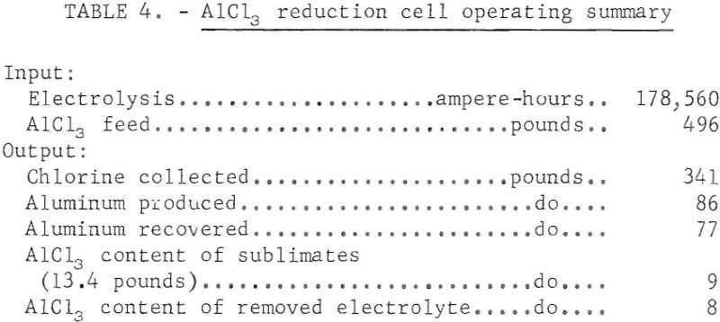
The anode current efficiency of investigative reductions, totaling 122.470 ampere-hours, was 76.5 percent. The investigation included many tests using less than optimum operating conditions. Individual test efficiencies were as high as 95 percent. Efficiencies of 80 to 85 percent were attained consistently, when utilizing the best operating conditions. The low-current-density idling reductions performed during unattended intervals totaled 56,040 ampere-hours and produced chlorine at 41.6-percent efficiency. Other factors which reduced efficiency were short anode-cathode distance, depressed temperature, resulting in either a mushy electrolyte or crust formation over
the electrolyte; or, before use of titanium diboride, an inferior electrical connection to the aluminum cathode. Short electrode separation and crusting of the electrolyte probably reduced cell efficiency by promoting rechlorination of aluminum in the vicinity of the anode. The discovery that aluminum beads were occasionally suspended in the lower portion of the electrolyte supports this supposition.
Incomplete coalescence of aluminum could have caused variations in voltage and efficiency in individual tests besides overall lowered efficiency and recovery. Observations were that the metal-electrolyte suspension alternately accumulated and receded for no apparent reason. No attempts were made to suppress bead formation, nor is it known what methods, other than fluoride addition which could have damaged the cell, would have been effective in promoting metal coalescence.
Evaluation of Cell Construction Materials
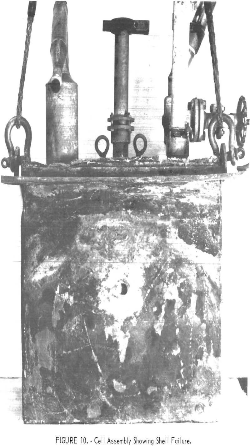
Cell operation was concluded because of a 1-inch hole which had burned through the shell from the outside when a piece of scale bridged the shell and a furnace resistance element. The shell failure, shown in figure 10, coincided with a fine crack in the refractory at the site of the imbedded thermocouple well .
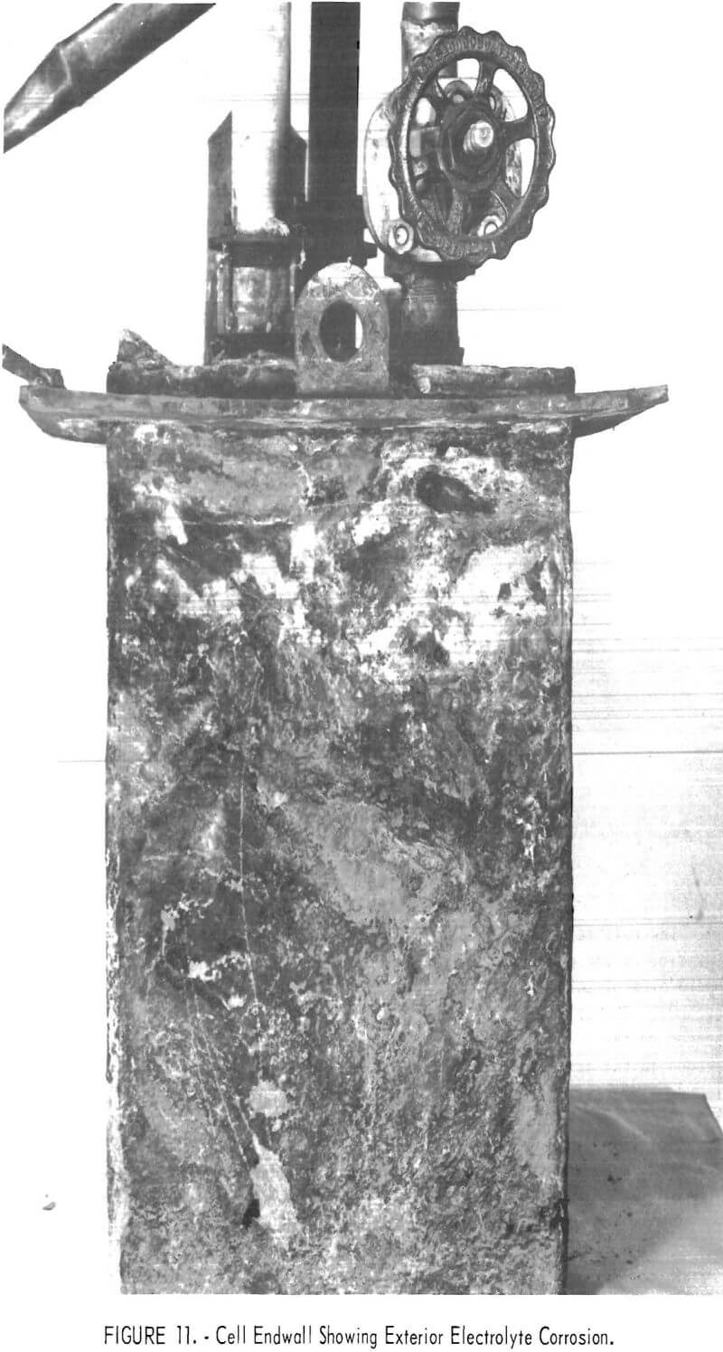
A slow steady loss of electrolyte had been indicated by bath measurements 2 weeks prior to failure, and its cause became apparent in disassembling the cell and furnace. Examinations during disassembly revealed that electrolyte absorbed by the cell refractory was conducted up the walls and through the roof where it was transferred to and absorbed by scale formed on the outside of the Inconel shell and steel supporting flange. Salts saturated scale on the shell down 5-½ inches below the supporting flange. Adjacent furnace brickwork and insulation cast over part of the cell roof were partially filled with salt. Most of the AlCl3 fed to the cell, but unrecovered as chlorine and aluminum, was probably contained in these salts outside the cell. One end of the exterior of the Inconel shell is illustrated in figure 11. Though covered with scale, the upper portion of which was salt-saturated, it was attacked externally only in a narrow band 1-¼ to 1-½ inches below the supporting flange (2-½ inches below the top edge of the shell). The attack was through the shell to solid refractory at two sites, one on each end of the cell. The two lift fittings projecting upwards from the flange apparently acted as barriers to passage of electrolyte, as there was no shell attack beyond them.
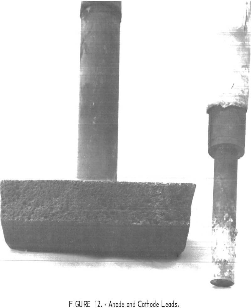
Disassembly of the cell provided more information on compatibility of the construction materials with the environment media. The final anode and cathode lead are shown in figure 12. The anode face was in good condition with no evidence of pitting or powdering, although the edges had been sufficiently eroded to reduce face dimensions by ½ inch. Eroded grooves were channeled in the direction of the chlorine flow to the exit. The titanium diboride cathode contact and supporting graphite lead were in excellent condition, but the alumina insulating sheath around them was eroded to the extent of shortening it 3-½ to 4 inches. The two previous anodes were used for shorter durations. They showed no evidence of reduction in size.
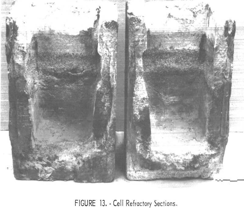
The cell refractory was sectioned, as shown in figure 13, to examine the interior of the cell chamber. The sidewall faces were unaffected in the freeboard area of chlorine exposure and in the area containing the molten aluminum cathode. The troweled facings were retained in these areas and were still bonded to the rammed refractory body. The sidewalls were, however, heavily eroded in the area at the surface of the electrolyte. Eroded pockets were found at each interior corner, and one of these was 1-½ inches deep. On the interior faces erosion was ¼ to ¾ inch deep over the 3 to 4-½ inches of varying electrolyte level. Individual refractory grain in the areas of erosion were hard and sharp, as was that recovered from the cell floor sludge. The erosion was principally directed towards the chemical bond of the refractory which had not been fired sufficiently to develop ceramic bonding. There was no evidence of corrosion to the interior of the Inconel shell.
Conclusions
The AlCl3 reduction cell performed satisfactorily within a wide range of operating conditions. The results of the investigation establish that aluminum chloride can be reduced electrolytically, both continuously and efficiently, to aluminum of good quality in a cell of simple design. The experimental cell was operated at 300° C lower temperature than a Hall-Heroult cell and with a less corrosive electrolyte. After solving problems of cathode electrical connections by substitution of titanium diboride for graphite, carbon consumption was limited to small anode losses.
Most of the problems encountered were associated with construction materials and external heating. Experience acquired in pursuing this investigation suggests improvements in design which would overcome these problems. A cell should be of size and construction to maintain its temperature by direct current alone. Supplemental alternating current supply through carbon resistance elements within the electrolyte would be useful in providing startup heat. The internally heated cell would, by establishing frozen salt containment, limit the mobility of the electrolyte through ceramics. Low-permeability, erosion-resistant, high-alumina ceramic would be most suitable to contain the electrolyte and chlorine. These properties are met by any of the denser grades of high-alumina refractory brick.
Titanium diboride or zirconium diboride are excellently suited for leads for cathode electrical connections. Although not required to promote efficiency, most consistent operation would result from continuous feeding of aluminum trichloride to maintain a constant aluminum content in the electrolyte.
