Table of Contents
To help assure an ample domestic supply of zinc and other essential minerals which provide the foundation of the Nation’s economy and security, the Bureau of Mines is investigating an aqueous chlorine-oxygen leaching procedure to produce zinc chloride from complex sulfide concentrates and is also studying methods of fused-salt electrolysis to produce special-high-grade zinc metal from the resulting purified zinc chloride.
Lead-zinc ores are often difficult to treat by conventional processes because the galena and sphalerite minerals contain interlocked pyrite and copper sulfide minerals. When these ores are processed by flotation, the resulting zinc concentrate has a complex composition. If the flotation circuit is operated to produce a better grade of zinc sulfide concentrate, zinc losses are typically high and overall recoveries are very low. Examples of these types of material are the Copperhill deposit in Tennessee and the Crandon deposit in Wisconsin.
Conventional smelting practice is not suited for the recovery of metal values from these complex sulfide concentrates; therefore, the Bureau of Mines is investigating a hydrometallurgical process to provide a more effective means to utilize these resources. Studies have been conducted and previously reported on a chlorine-oxygen leaching system for extracting metal values from these concentrates, which are complex in composition.
In the Bureau-developed system, a water slurry of the concentrate is reacted sequentially with chlorine and oxygen in a pressure reactor. The resulting leach solution and reactor residue are treated to recover separate purified lead and zinc chlorides. The chloride salts are subsequently treated by fused-salt electrolysis to produce lead and zinc products and chlorine gas for recycle to the leaching step. A simplified flowsheet of the process is shown in figure 1.
In addition to the chlorine leaching system, the Bureau has also conducted research on the fused-salt electrolysis of both lead and zinc chlorides. In 1976, Bureau reports were issued on small-scale research efforts to electrowin lead from PbCl2 in a KCl-LiCl-PbCl2, eutectic fused-salt bath and zinc from ZnCl2 in KCl-LiCl-ZnCl2 baths. The developmental work was conducted in 1,000-ml Pyrex beakers with small graphite electrodes. Larger scale, fused-salt electrolysis of PbCl was reported more recently.
In 1979, the Bureau issued another report in which the effect of composition on bath stability, current efficiency, cell voltage, and liquidus temperature was determined for ZnCl2-NaCl-KCl, ZnCl2-NaCl-LiCl, and ZnCl2-KCl-LiCl electrolyte systems. This report also discussed the design, construction, and short-term operation of a 1,500-amp monopolar, fused-salt cell.
The objective of the work reported in this paper was to design, construct, and operate a 2,000-amp, monopolar, fused-salt zinc electrolytic cell to determine the effects of temperature, electrode gap, current density, electrolyte composition, and electrode configuration on current efficiency and energy consumption and to investigate bipolar electrode configurations. Operating data, obtained from long-term continuous operation of both monopolar and bipolar electrode cells, will enable engineering design for a commercial-size

cell and will allow a reasonable estimate of both capital and operating costs for producing special-high-grade zinc from purified zinc chloride feed material.
Special attention was given to the problem of sludge formation reported in earlier test work. This problem was resolved by operating on a continuous, rather than an intermittent, basis.
Monopolar Cell Test Materials, Equipment, Procedures
Description of 2,000-Amp Monopolar Cell
The general design of the cell was similar to that of the 1,500-amp monopolar cell reported earlier except for revisions in size, materials of construction, and electrode design. Figure 2 shows a cross-sectional view of the monopolar fused-salt cell. The electrolyte chamber was approximately
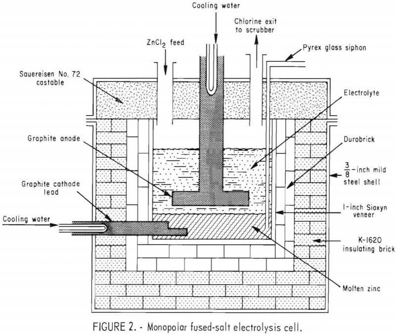
26 inches long by 20 inches wide by 18 inches deep and was lined with a ¾- inch veneer of Sioxyn (silicon oxynitride). The veneer was backed by two layers of 2½-inch-thick acidproof brick (Harbison-Walker Durobrick) and insulated with a 5-inch thickness of insulating brick (Babcock and Wilcox K-1620) on the bottom and sides. The cell was encased in a 3/8-inch-thick mild steel shell, 50 inches long by 44 inches wide by 38 inches high.
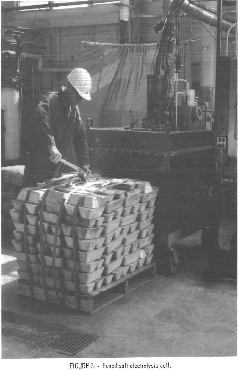
The monopolar electrode system consisted of a horizontal graphite anode constructed from ATJ-grade graphite, and the molten zinc pool served as the cathode. The graphite anode was 18 inches by 12 inches by 2 inches thick and had ½-inch-wide grooves in the lower surface that were inclined at 3° to facilitate the escape of the chlorine. Six parallel grooves were cut in the long axis of the anode and slanted from a 1/8-inch depth on one end to a 1- inch depth on the other end so that the flow of chlorine was directed to one end of the electrolyte compartment. The cathode lead was also ATJ-grade graphite, but the molten-zinc pool at the bottom of the electrolyte compartment served as the cathode. This arrangement allowed the electrode gap to be changed by increasing or decreasing the level of the zinc pool cathode. Electrical contact for the anode was a 6-inch-diameter graphite rod threaded into the anode plate. Both the anode and cathode leads were protected from oxidation by inserting a water-cooled copper block connector cemented in place with a highly conductive silver paste. The zinc level was monitored with a uranium glass-encased tungsten rod with the tip exposed and extending from the bottom of the zinc pool up through the cell lid. By measuring the voltage drop between the anode lead and the tungsten rod, while raising the rod, it was possible to detect when the tip of the rod was no longer in contact with the molten zinc, thus determining the zinc level in the electrolyte compartment. Ports were provided in the lid for chlorine exhaust, zinc chloride feed, thermocouple wells, immersion heater wells, level sensor, and a Pyrex glass siphon to remove molten zinc from the cell. The ports were lined with Hastalloy B-2 pipes welded to the steel shell of the lid and extending through the castable ceramic in the lid. A mild steel vacuum chamber, mounted on top of the lid, was employed to withdraw molten zinc from the cell into a cast iron mold located within the vacuum chamber. Chlorine was exhausted from the cell through a section of 4-inch CPVC (chlorinated polyvinyl chloride) pipe to a 12-inch-diameter soda ash scrubbing column. The first 3 feet of CPVC pipe was water cooled. An overall view of the fused-salt electrolysis cell with the chlorine scrubbing system in the background is shown in figure 3.
Cell Feed Material
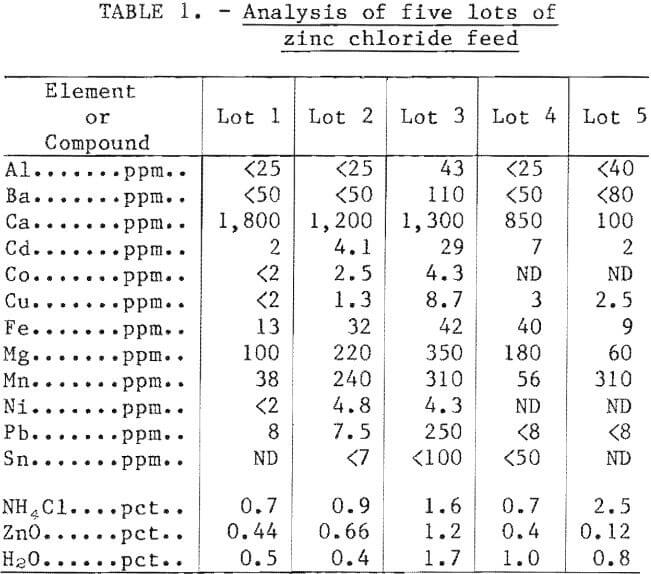
The capacity of the fused-salt electrolysis cells made it impractical to produce the required amount of zinc chloride feed from sulfide concentrate. Therefore, commercially available purified zinc chloride was used for all operations in the fused-salt cells. More than 24,000 pounds of zinc chloride were used throughout the extended operations of these larger scale monopolar and bipolar cells. Table 1 shows typical chemical analyses of various lots of zinc chloride used in the study.
Operating Procedure for 60-Day Run
Direct current was supplied by a constant-current, silicon-controlled rectifier. Alternating current for initial bath meltdown and auxiliary heating was supplied to four 3,000-watt, resistance immersion heaters inside 1½-inch-diameter quartz thermowells. The initial electrolyte charge was 480 pounds of a mixture containing 38 mole-pct (55 wt-pct) ZnCl2, 31 mole-pct KCl, and 31 mole-pct NaCl. At 500° C the molten electrolyte had a density of about 1.9 g/cm³, and 480 pounds filled the cell to a depth of about 14 inches. During the first week of operation, molten electrolyte seeped into the brick lining, and an additional 600 pounds of salt mixture was added to the cell to maintain the electrolyte level. Zinc was not withdrawn from the cell during the first 6 days of operation so that the zinc level could build up. After the zinc level reached the desired height, the zinc was periodically withdrawn to maintain a constant electrode gap for each operating condition that was investigated. Zinc chloride was added to the cell manually through a feed port at a rate sufficient to maintain a nearly constant electrolyte composition and level. Bath composition was monitored by atomic absorption analysis of periodic electrolyte samples. Periodic feeding ranged from every 2 hours to every 12 hours depending on the operating current density. The temperature was maintained nearly constant by controlling the interplay of direct current electrolysis heating, alternating current immersion heating, and air cooling. Heat addition was maintained by a continuous proportional band alternating current control device, and heat removal was controlled by the rate of cooling air flow; thus, the temperature was maintained to within approximately ±3° C of the desired electrolyte temperature. Current used in electrolysis was measured using an integrating ampere-hour meter.
Results of Monopolar Cell 60-Day Run
A summary of the operating data obtained over the 2-month continuous operation of the monopolar cell is shown in table 2. The effects of temperature, electrode gap, current density, and electrolyte composition on current efficiency and energy consumption were determined for the KCl-NaCl-ZnCl2 electrolyte system.
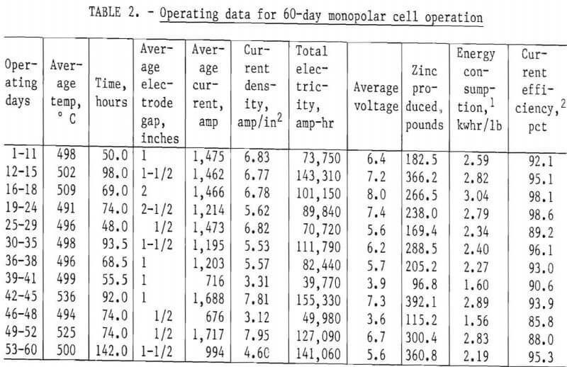
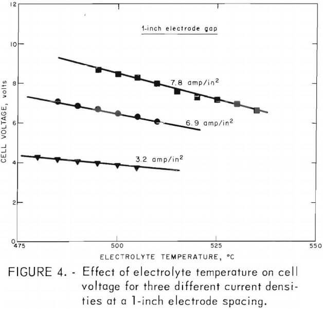 Figure 4 shows the effect of electrolyte temperature on cell voltage at three different current densities. An increase of 50° C in electrolyte temperature can decrease electrolyte resistivity, cell voltage and thus dc power consumption by approximately 30 pct at an anode current density of 7.8 amp/in² (3.3 amp/in² cathode current density).
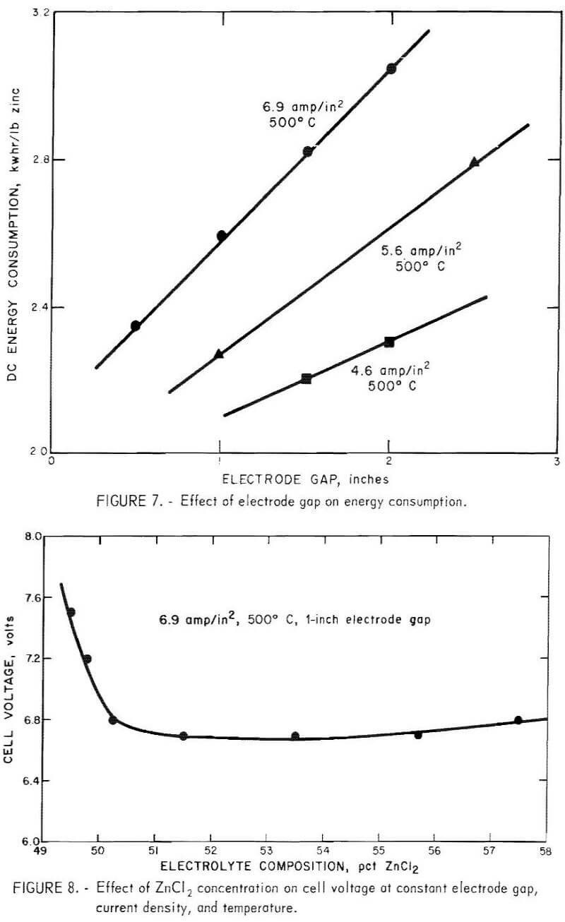
Current density and electrode spacing are two of the most important variables and determine both the size of cell and the energy required for a prescribed metal production. Tests to illustrate their effect were made at 500° and 525° C with the ZnCl2-KCl-NaCl bath containing about 50 to 60 wt-pct (32 to 42 mole-pct) ZnCl2. The results, illustrated in figure 5, show how the cell voltage and thus the dc energy consumption were affected by both current density and electrode gap. The current efficiency and dc energy consumption were calculated for each condition studied. Figure 6 shows the effect of electrode gap on current efficiency for several current densities and at two temperatures. Current efficiencies greater that 93 pct were obtained at electrode gaps of greater than 1 inch, but as the electrode gap was increased, the cell voltage, and thus the dc energy consumption, increased approximately linearly, as shown in figure 7.
The effect of zinc chloride concentration in the electrolyte was investigated in a series of experiments at constant electrode gap, current density, and temperature. Even though the initial composition was 55 wt-pct (38 mole-pct) zinc chloride, as the zinc was electrolyzed and more zinc chloride was added to the cell, the zinc chloride composition fluctuated. During most of the run, the zinc chloride content was maintained between about 50 and 58 wt- pct zinc chloride. Figure 8 shows how fluctuations in the zinc chloride content of the electrolyte affected the cell voltage at constant electrode gap, current density, and temperature. The voltage was nearly constant above about 50 pct zinc chloride but increased rapidly as the electrolyte became depleted in zinc chloride. A slush or sludge, on top of the molten zinc, was also noted when the electrolyte became depleted in zinc chloride. A good correlation was observed between the rise in cell voltage and slush formation. As soon as additional zinc chloride was added to the cell, the 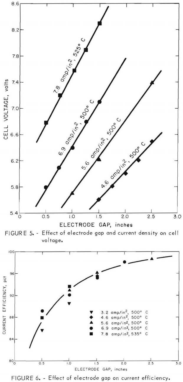 voltage dropped and the slush layer on top of the zinc disappeared. This condition may have been the cause of the so called sludge problem reported earlier. If electrolyte composition was properly controlled, the sludge problems encountered earlier could have been avoided. In small-scale tests, metallic impurities, such as chromium, molybdenum, and tungsten, tended to accumulate at the electrolyte-zinc interface and caused poor coalescence of the zinc beads as they formed on the surface of the zinc pool. This could also have been part of the “sludge problem” reported earlier. Oxide formation was not a problem in the cell when it was operated continuously; however, in the work reported earlier, the cell was operated intermittently and oxide sludge may have formed under those conditions.
Using extrapolation of the experimental data, the current efficiency and dc energy consumption were calculated to determine the best electrode spacing for this particular monopolar cell. Since the temperature of the electrolyte drastically affected the cell voltage, and thus the dc energy consumption, a temperature of 535° C was assumed for the calculated data. The data indicated maximum metal production per energy input was achieved with an electrode gap of about ½ inch at an anode current density of about 6 amp/in² (2.5 amp/in² cathode current density). Since
there is a trade-off between capital cost and operating cost for low-current-density cells, a commercial cell would probably be operated at an anode current density that would minimize total capital and operating costs.
A material balance showed that at 500° C, approximately 4 to 5 pct of the total zinc chloride fed to the cell in a 5-day period was vaporized and lost in the scrubber, while at 535° C, approximately 9 to 10 pct was lost in the same amount of time. Therefore, even though the higher temperature results in better energy efficiency, a balance between energy efficiency and zinc chloride vaporization, which would require a system of collection and return to the cell, must be maintained.
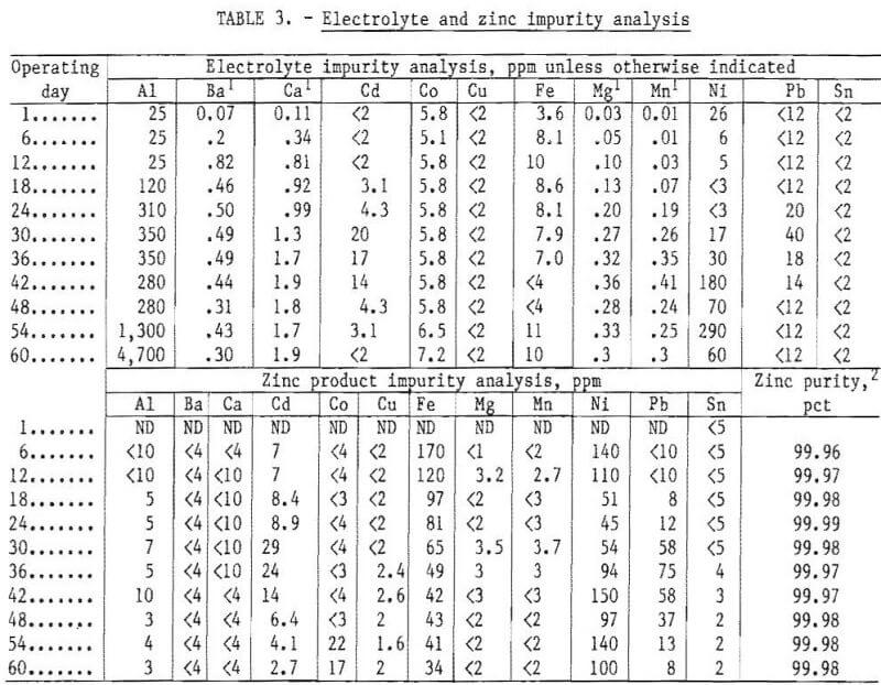
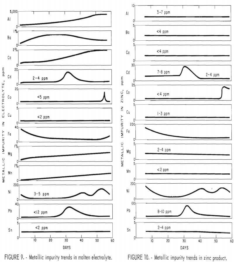
Figures 9 and 10 show the trends in impurity analyses for both electrolyte and zinc samples taken from the monopolar cell during the 60 days of operation. Aluminum, barium, calcium, magnesium, and manganese continued to build up in the electrolyte, and iron, nickel, cadmium, copper, cobalt, lead, and tin remained fairly constant in the electrolyte. The opposite effect was observed in the zinc product with low impurity analysis for aluminum, barium, calcium, magnesium, and manganese. Since the feed material was also low in tin and copper, these elements were in turn low in the metal. The iron and nickel analyses varied during the run depending on the amount of contamination from the cell construction materials. The lead and cadmium content of the metal followed directly the content in the feed material; that is, while the high-lead-cadmium-containing feed material was being used, there was a marked increase in the lead and cadmium content of the metal.
The cobalt showed a marked increase in both electrolyte and metal samples during the last week of operation. The increase was directly due to the cobalt chloride addition to the feed material to demonstrate the effects of high-cobalt feed material. These data are summarized in table 3.
Bipolar Cell
Bipolar Concept
In a monopolar, multiple-electrode system, the anodes and cathodes are connected in parallel with each electrode pair attached to the direct current source. In a bipolar or series system, only the end electrodes are connected to the direct current source; intermediate plates have no direct electrical connection and are insulated from each other. During electrolysis, the intermediate plates become bipolar, with anodic reactions occurring on one side and cathodic reactions on the other, but there is no significant separation of charge. Each pair then acts as a cell in series with every other pair, increasing the voltage and deposition rate by (n-1) times the number of plates. This is a tremendous advantage over the monopolar arrangement because the amperage can be greatly reduced for the same production rate—thus minimizing the size and the cost of electrical equipment and busbar. Cell design is also simplified because only two electrode connections are required, regardless of the number of plates. It should be noted, however, that the overall current efficiency with a bipolar arrangement is always less than with a monopolar arrangement because of current leakage around the edges of the intermediate plates. Nevertheless, a lower energy consumption is possible with a bipolar arrangement simply because more heat is generated with multiple electrodes and a heat balance can be obtained at a lower current density.
Description of Initial Bipolar Cell
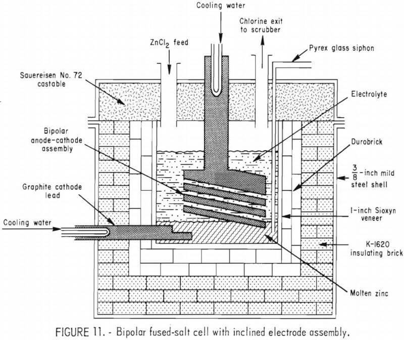
After the 60-day continuous operation of the monopolar cell was completed, a bipolar electrode assembly was constructed using the same electrolyte compartment and cell lid used for the monopolar cell study. The first bipolar electrode arrangement employed 1-inch-thick graphite plates and slices of Durobrick as spacers between the plates to support the plates at a 15° incline. Durobricks were used to insulate two edges of the graphite plates to minimize current leakage around the edges of the intermediate plates. All other components of the system were the same as those described for the monopolar cell.
The bipolar cell, shown in figure 11, had a ½-inch electrode gap for each electrode pair and was operated continuously for 19 days. Approximately 4,000 pounds of commercial zinc chloride was used during the initial bipolar cell test. The zinc level was permitted to build up in the bottom of the electrolyte compartment during the first 4 days of operation so that good electrical contact was made with the bottom graphite plate. After the zinc level reached the desired height, the cell was operated at a constant current density for periods of 3 to 4 days. The efficiency and energy consumption of the bipolar assembly were determined at each current density selected for study. Results of the first test showed the average current efficiency for the assembly was only about 50 pct, and the average energy consumption was about 2.5 kwhr/lb of zinc.
Other Bipolar Assemblies Tested
In view of the low overall current efficiency and high average energy consumption obtained with the initial bipolar assembly tested, and as a result of additional laboratory experiments conducted in small fused-salt cells, it was concluded that two factors contributed to these results:
- A portion of the molten zinc forms as very small droplets on the graphite cathodes and can readily become suspended in the chlorine-saturated molten electrolyte and thus be rechlorinated. This causes a significant decrease in the overall calculated current efficiency.
- A portion of the electrical current was bypassing the lower electrodes and flowing through the molten electrolyte directly to the molten zinc pool at the bottom of the cell. These electrical shunt losses also resulted in a decrease in overall current efficiency as well as affecting the average energy consumption per pound of metal produced.
To test these hypotheses, four different bipolar assemblies were designed, constructed, and operated for approximately 20 days each to establish a relationship between average current efficiency and energy consumption as a function of current density for each of the four bipolar electrode designs.
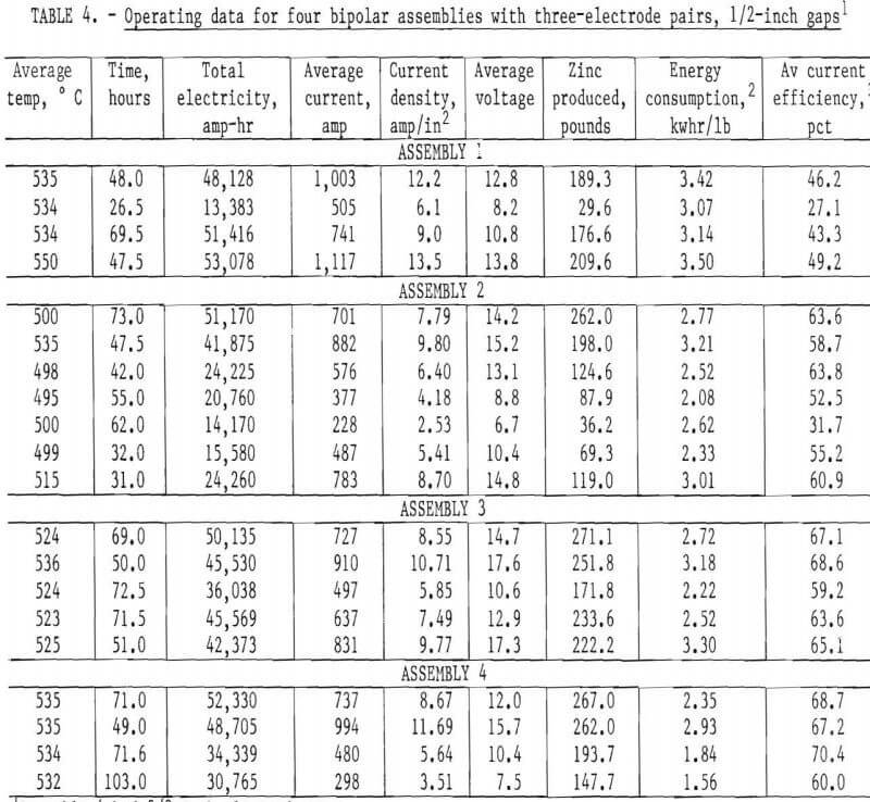
Assembly 1 was constructed using a bipolar stack with graphite anodes and cathodes with no ceramic insulation on the edges of the bipolar stack. The average current efficiency for this assembly was less that 50 pct at all current densities tested, and the energy consumption ranged from 3.1 to 3.5 kwhr/lb of zinc produced.
For assembly 2, the same bipolar stack with graphite anodes and cathodes was used, but the edges of this assembly were shielded using a ¾-inch-thick ceramic insulating plate to minimize current shunt losses. The plate had 1/8- inch-wide slits cut parallel to each electrode gap to allow electrolyte circulation as the chlorine gas, generated at the anode surfaces, exited the electrode gaps. Results of tests conducted with this assembly gave a maximum average current efficiency of about 64 pct at a current density of 6.4 amp/in². At those conditions, the energy consumption was about 2.5 kwhr/lb of zinc produced.
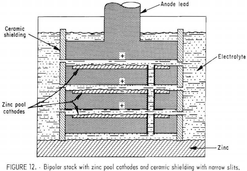
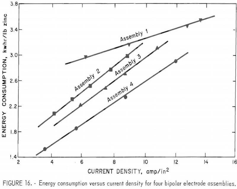
Assembly 3 was constructed using graphite anodes, but the graphite cathodes were machined to give a ¼-inch recess so that a molten zinc pool could build up on each cathode surface as shown in figure 12. The electrode assembly shielding was the same as used with assembly 2. Test results showed an improved overall current efficiency and energy consumption which indicated that there was an advantage to using zinc pool cathodes rather than graphite. The zinc pool cathodes eliminated the formation of small zinc droplets on the cathode surface and minimized the chance of zinc rechlorination. The energy consumption was approximately 8 pct less with assembly 3 than with assembly 2.
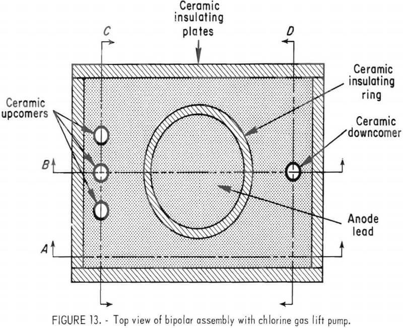
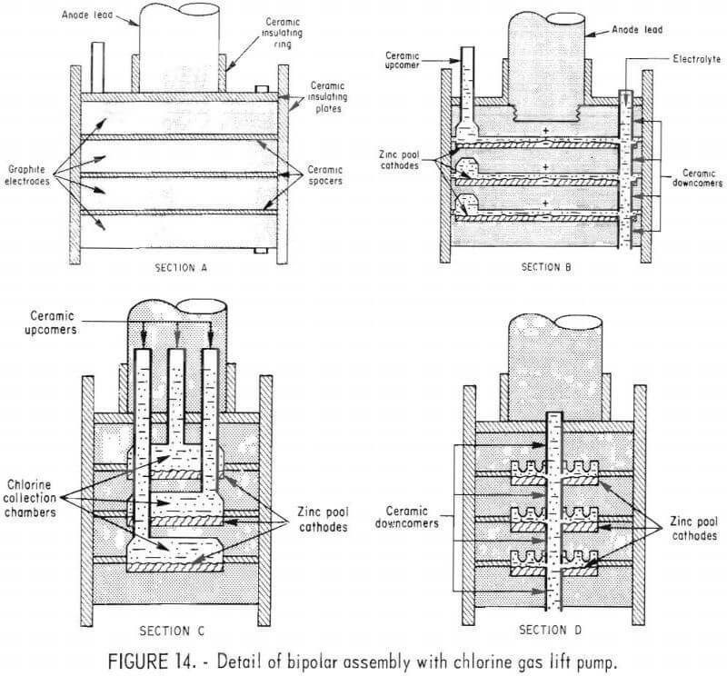
Best results were attained using a three-electrode-pair, bipolar assembly with provisions for electrolyte circulation using ceramic tubes to direct the movement of chlorine, molten zinc, and electrolyte (assembly 4). The system was designed so that, as the chlorine gas exited the interelectrode gap, the electrolyte was circulated by differential density pumping through each gap. Figures 13 and 14 show different views of the electrode assembly. Figure 13, the top view of the assembly, shows the anode lead, three ceramic upcomer tubes for chlorine and spent electrolyte discharge, and one ceramic downcomer for fresh electrolyte feed.
The four graphite electrodes, shown in figure 13 and 14, provide electrical conductance and surfaces for the electro-chemical reactions to take place. The bottom surfaces of the three upper electrodes are anodic, and tops of the three lower electrodes are cathodic as shown by the plus and minus signs in figure 14, section B. Section A of figure 14 also shows how ceramic spacers are used to electrically isolate the graphite plates from each other and the surrounding electrolyte bath.
Section B of figure 14 shows the position of the center ceramic upcomer, which carries the chlorine and spent electrolyte above the surface of the electrolyte bath, and the ceramic downcomers, which carry the fresh electrolyte feed into the interelectrode gaps and the molten zinc down to the molten zinc reservoir at the bottom of the cell. Also shown is the anode lead connection to the top electrode.
Section C of figure 14 shows the chlorine collection chambers on the anode surfaces and the position of the three ceramic upcomer tubes which carry the chlorine gas and spent electrolyte from the respective interelectrode gaps.
Section D of figure 14 shows the position of the ceramic downcomer tubes which carry fresh electrolyte into the interelectrode gaps, and molten zinc out of them. Also shown on this figure is the pattern of grooves to provide anodic surface which is not covered by an insulating gas blanket.
A significant improvement was achieved with this assembly—almost complete electrical isolation of each electrode was attained by using ceramic tubes to direct the chlorine, electrolyte, and zinc as indicated in the discussion of figures 13 and 14 and by cementing ceramic plates to all four sides and the top of the assembly. This eliminated current shunt losses from the upper electrodes through the electrolyte bath directly to the zinc pool at the bottom of the cell. The ceramic insulating plates and the ceramic spacers between the graphite electrodes were constructed from Sioxyn. All the ceramic materials, including the upcomer and downcomer tubes, the electrode spacers, and the electrical insulating plates, were cemented in place using a Contronic 914 ceramic adhesive.
The results obtained from continuous operation of the four different, three-electrode-pair, bipolar assemblies are tabulated in table 4 and shown graphically in figures 15 and 16.
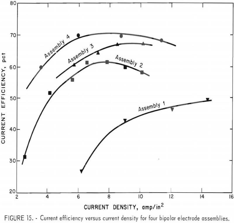
Even though the overall current efficiency is lower, for the bipolar assemblies studied, when one compares the energy consumption of the bipolar cell with that achieved with the monopolar cell, with a zinc pool cathode, there is a significant improvement, particularly with assembly 4. As an example, at an anode current density of 5 amp/in² the monopolar cell with about a 3/8-inch electrode space would operate at a current efficiency of about 85 pct and a power consumption of about 2.0 kWhr/lb of zinc produced. The bipolar cell with assembly 4 using a 3/8-inch electrode space operated at about 66 pct average current efficiency for three-electrode pairs. This would be equivalent to 87 pct current efficiency for each of the three-electrode-pairs. However, power consumption of only 1.7 kwhr/lb of zinc produced was achieved for the three-electrode pair, shielded bipolar assembly, operating at a current density of 5 amp/in².
If one compares the metal production on an ampere-hour bases, the monopolar cell yielded an average 2.51 pounds of zinc per 1,000 amp-hr compared with 5.24 pounds of zinc per 1,000 amp-hr, achieved with bipolar assembly 4.
Conclusions and Discussion
Based on extended periods of continuous operation of pilot-scale electrolytic cells, the electrolysis of purified ZnCl2 in a KCl-NaCl-ZnCl2 fused-salt bath is a promising method for producing special-high-grade zinc.
Fused-salt electrolysis offers potential advantages over the present aqueous electrolysis process because much higher current densities can be employed to increase production per unit volume, and considerably less manpower is required because stripping of cathode metal and remelting for casting is not required.
A bipolar electrode design has the advantage that the amperage can be greatly reduced for the same production rate, thus minimizing the size and the cost of electrical equipment and busbar. Cell design is also simplified because only two electrode connections are required regardless of the number of plates. However, the problem of decreased current efficiency must be overcome before the advantages of a bipolar cell are apparent. Efficiencies were significantly improved in this study by using a chlorine gas pump to circulate electrolyte, by using molten-zinc-pool cathodes, and by electrically insulating the bipolar stack. Research is continuing to find methods to further improve the overall current efficiency and energy consumption of the bipolar fused-salt cell.
Evaluation of the data accumulated during a 60-day continuous operation of a 2,000-amp, monopolar cell and several 10- to 30-day runs with five different bipolar assembly cells has led to the following conclusions:
- Maximum zinc production per kilowatt-hour of power consumed for the monopolar electrode assembly can be attained with less than ½-inch electrode spacing and at a current density less than 6 amp per square inch of anode area.
- Energy consumption is minimized if the cell is operated at the maxi-mum temperature allowable for the cell design, electrolyte composition, and cell construction materials; however, excessive zinc chloride losses occur at higher temperature.
- The zinc chloride content should be maintained in the range of 52 to 58 wt-pct zinc chloride, for electrolysis from the ZnCl2-KCl-NaCl electrolyte system at 500° C, to achieve optimum energy efficiency and to avoid formation of sludge at the electrolyte-molten metal interface. At higher zinc chloride content, excessive evaporation will occur.
- Zinc chloride purity must be controlled with respect to metallic impurities, such as cadmium, cobalt, copper, iron, nickel, lead, and tin. Presence of these impurities in the cell feed results in a direct transfer to the metal product.
- Impurities such as aluminum, barium, calcium, magnesium, and manganese will build up in the electrolyte and probably necessitate an electrolyte bleedstream or additional purification of zinc chloride feed. A total impurity content of approximately 20 pct of these metal chlorides did not have any noticeable effect on the cell operation for the ZnCl2-KCl-NaCl electrolyte.
- Prolonged contact between molten electrolyte and any metal must be avoided. Hastalloy B metal inserts in some of the lead-through tubes in the lid were a source of electrolyte and metal contamination.
- Metallic impurities such as chromium, molybdenum, and tungsten accumulated at the electrolyte-zinc interface and caused poor coalescence of the zinc beads as they formed on the surface of the molten zinc pool.
- Graphite anode wear was minimal with only about 6 pct change in anode volume in 60 days even with ZnCl2 feed containing up to 1.7 pct moisture.
- A maximum current efficiency of about 70 pct was attained with a three-electrode-pair bipolar design: however, both current efficiency and energy consumption were significantly improved using a chlorine gas pump to circulate electrolyte and ceramic insulation to shield the edges of the electrode stack. With this type of assemble (shown in figures 13-14), zinc was produced at an energy consumption rate of 1.7 kwhr/lb of zinc compared with 2.1 kwhr/lb of zinc in an equivalent monopolar cell.
To help insure the continued viability of the minerals and materials sector of the U.S. economy, the Bureau of Mines is conducting research and disseminating technology that will result in more efficient minerals extraction. As part of this effort, a process is being investigated that involves an aqueous chlorine-oxygen leaching procedure to treat complex sulfide concentrates to produce ZnCl2. Subsequent fused-salt electrolysis of the ZnCl2 produces high-purity zinc metal. Previous reports described preliminary, small-scale research on the chlorine-oxygen leaching system and fused-salt electrolysis of ZnCl2. This report discusses the details of design, construction, and long-term, continuous operation of both monopolar and bipolar fused-salt cells.
The effects of temperature, electrode gap, current density, electrolyte composition, and electrode configuration on current efficiency and energy consumption were determined for a ZnCl2-KCl-NaCl electrolyte system. Zinc metal was produced at the rate of about 50 lb/day in a monopolar cell which was operated continuously for 60 days with current efficiencies from 85.8 to 98.6 pct and an average power consumption of 2.1 kwhr/lb. Bipolar cells with several different electrode configurations were operated for 90 days. A current efficiency of about 70 pct and power consumption of about 1.7 kwhr/lb of zinc were achieved using a three-electrode-pair, bipolar assembly with a chlorine gas lift pump to circulate electrolyte.

