Table of Contents
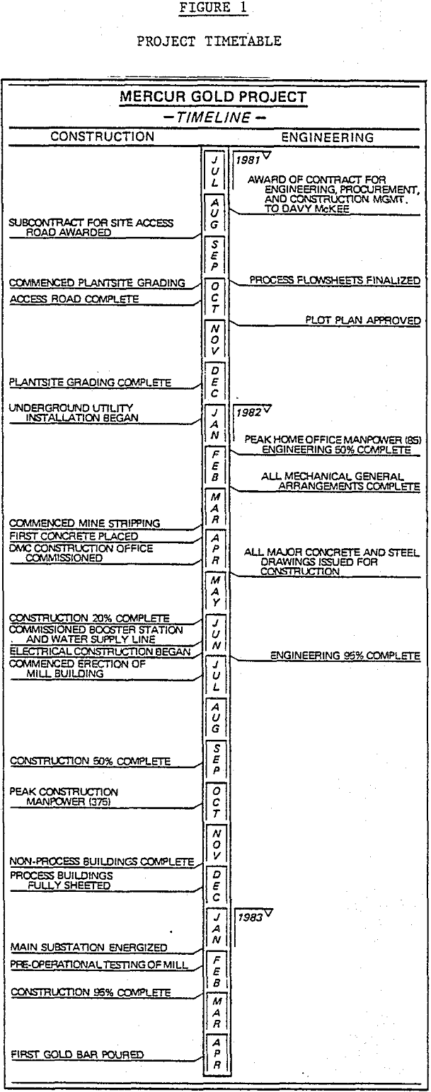
The pouring of the first dore bar on April 21, 1983, marked the conclusion of an engineering and construction project which brought about the revival of mining in Mercur Canyon, 105 km (65 miles) southwest of Salt Lake City, Utah. Previous mining activity in the canyon had ceased at the beginning of World War II, when all gold mines were shut down. The Mercur Project was completed under budget and six weeks ahead of schedule.
Project Description
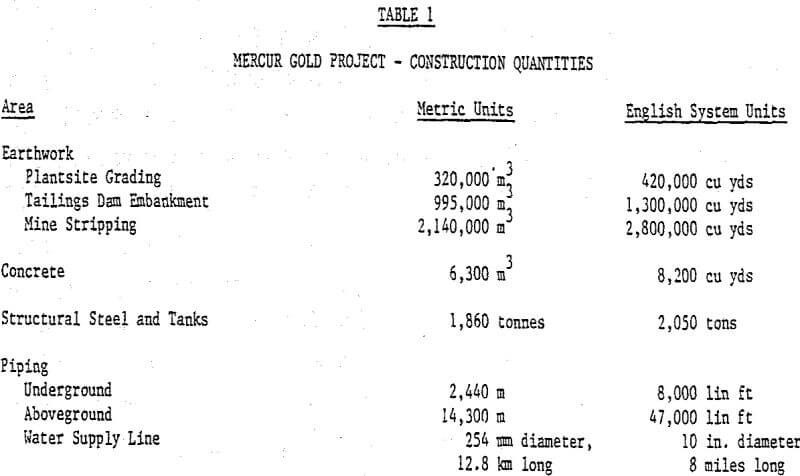
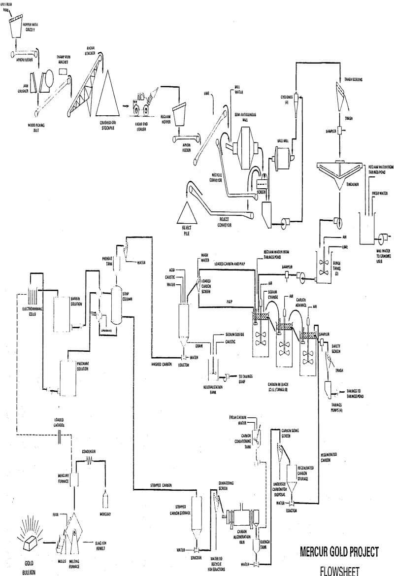
The Mercur Gold Project consists of a 2700 tonne (3000 ton) per day carbon-in-leach (CIL) gold plant. In addition to the process facilities, the project incorporated the following:
a) Upgrading and modifying of the existing 11 km (7 miles) of Tooele County road, from State Highway 73 to the project area
b) Site earthwork, including construction sediment dams, project area roads and initial mine haul roads
c) Preproduction stripping of Mercur Hill-Lulu ore body
d) Tailings disposal, including embankment, pipeline and recovery systems
e) Offices, laboratory, shops, warehouse and security facilities
f) Thirteen km (8 mile) water supply line and two 365-m (1200-ft) deep water wells.
In order to meet both objectives, initial discussions centered on the plot plan and the best location for the facilities, including consideration of the possible need for an oxidation circuit and future expansion requirements. The approximate sizes of the major process areas were developed and “cutouts” made to match the scale of a topographic map of the area.
Engineering Design
The engineering design schedule for the project required a multiple task approach with design activities underway on several areas at the same time. Communication between each activity was maintained by establishing a project area where all major activities took place. Frequent design development meetings were held so that representatives of all aspects of the project could provide input.
The initial flowsheet contained several areas which required further definition. Test work was underway to determine the residence time required for CIL and a study was conducted on the need for pressure oxidation. While this work was going on, specifications for the major process equipment in the comminution circuit were being written. Several alternative layouts were developed for the mills and mill drives. In order to quickly establish the optimum configuration of the mills, a styrofoam model was constructed representing the mills, cyclone feed sump, cyclones, screens and pumps.
The requirements of the short construction schedule also impacted the detail engineering phase of the project. In order to get concrete and steel drawings to the field in a timely manner, it was necessary to begin design of the major equipment and structure foundations and structural steel before the process was finalized. The small amount of engineering time lost with changes was more than made up for by the availability of drawings for construction. The need for completed foundations at an early date also placed emphasis on vendor expediting for the required information. An automatic system of expediting vendor drawings was initiated to keep the project informed of the key dates in this area. Particular emphasis was placed on the equipment that required engineering interface for foundation, piping or electrical design.
Non-Process Facilities
In addition to the process facilities, the project includes a mine services building which houses a truck shop, mining engineering and geological offices, and a machine shop and maintenance area. Due to the severe space restrictions on the site, all of these facilities were combined into a single unit located so that the mine haul trucks could access the building without entering the process area and so that the process maintenance facility could be near the major process facilities. In addition to the mine services building, a laboratory building, administration building and gatehouse were provided.
Other ancillary facilities included water supply facilities, electrical distribution and a tailings pond embankment. The 79-m (260-ft) high tailings pond embankment design required extensive field work, which was accomplished during the fall of 1981. With this work completed, the design and permitting process inherent in a structure of this type was completed over the winter and the field construction began in the following spring.


