DESCRIPTION
TROUBLESHOOTING PROCEDURE WHEN PULVERIZER WON’T START
First check :
- to ensure air pressure is 90-94 psi
- to ensure pressure gauge is functioning properly
- if the PLC display operates this confirms there is power going to the machine
- to ensure the electric motor is mechanically functional (full rotation)
- to confirm the door is closed and also the electrical interlock to allow the machine to start
INSTRUCTION MANUAL FOR VIBRATORY RING PULVERIZER MODEL 4×1000
Contents
- Description
- Installation
- Electrical Connections
- Maintenance
- Operating Instructions
This manual is the only instruction needed for keeping and maintaining the V.R.P. in operating conditions. Read it carefully before operating the Pulverizer.
We do not supply manufacturing drawings, production, and technical information that don’t pertain to the operation and use of the machine. If any additional information is required to operate or repair this machine, please contact our service department.
We decline all responsibilities if mishaps occur due to unqualified person wiring and manipulating the electrical system of this machine.
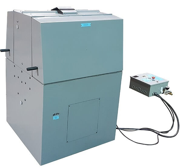
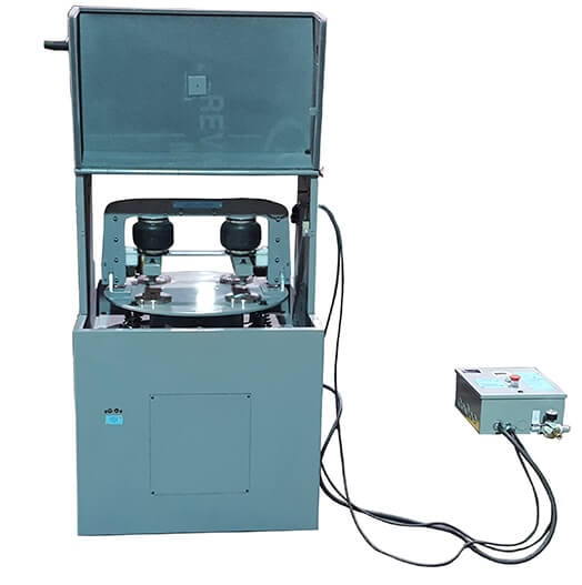
Description
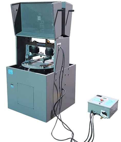
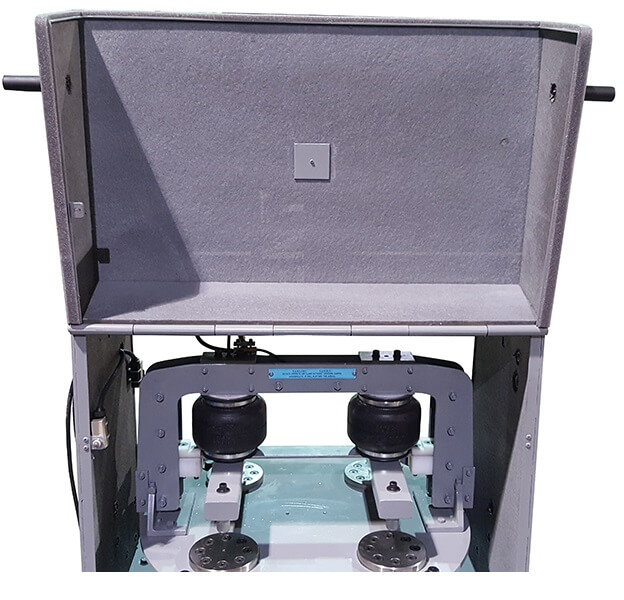
This Vibratory Ring Pulverizer consists of:
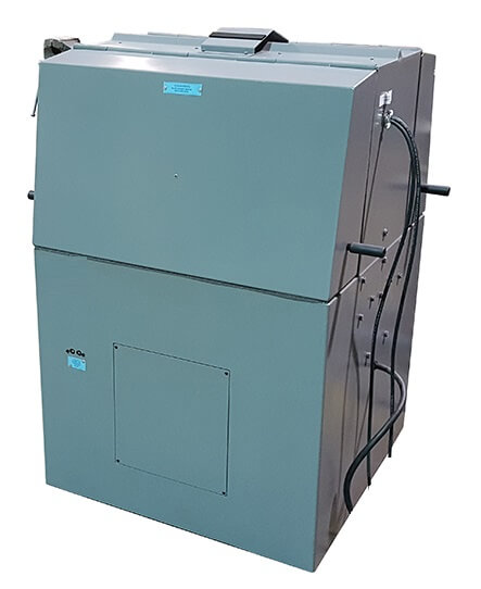
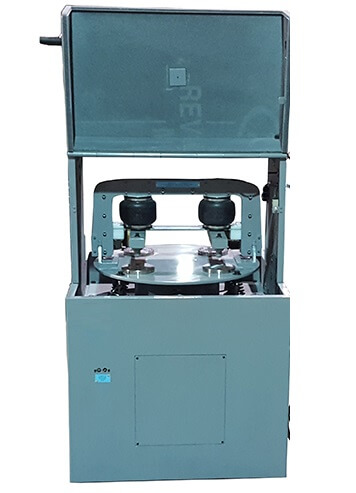
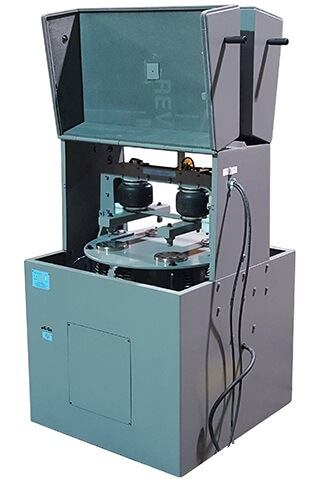
- Sound dampening enclosure with hinged door.
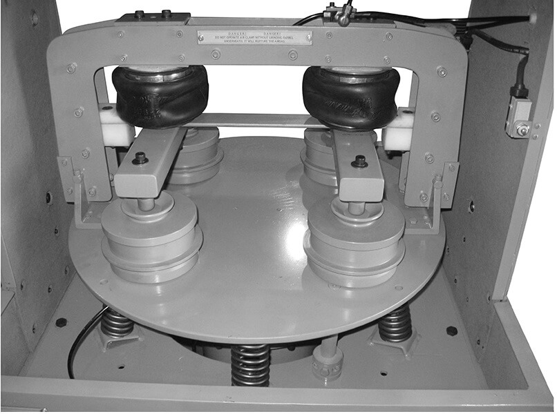
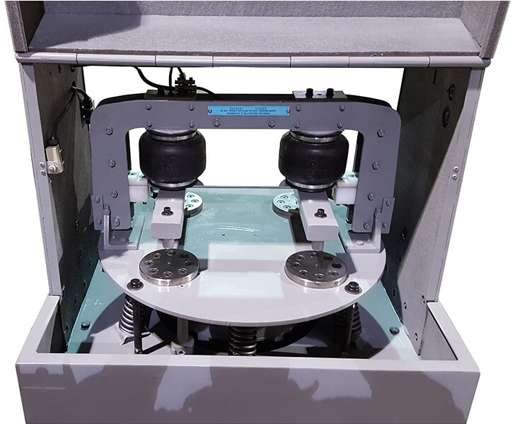
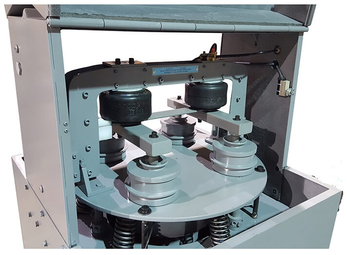
- Vibratory body with clamping system.
- Electric motor
- Control panel
- Grinding Barrel(s)
- Air Hoist(s) (for machines supplied with them)
The grinding barrel(s) are mounted and locked on the vibratory body with the air bag self adjusting clamping device. The hinged doors should be closed during operation.
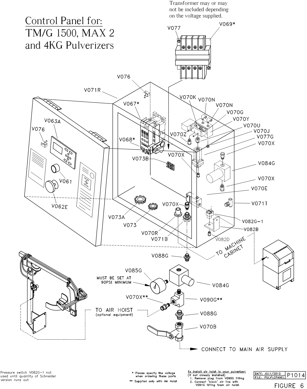
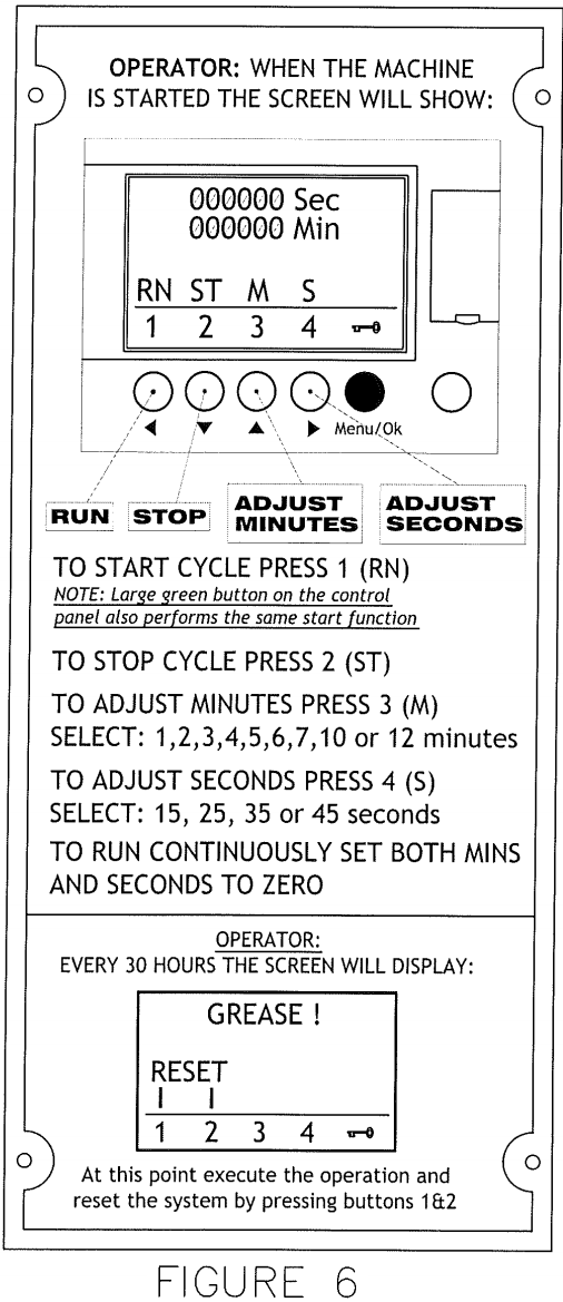
The control panel has a green start button (V061), an emergency red stop button (V062E), and a PLC (V063A). See Figure 6. To start the grinding cycle, one can either use the soft key ‘DEL’ on the PLC touch pad or alternatively the green start button. Should one want to stop a grinding cycle before the expiration of the pre-set time, the soft key ‘ALT’ on the PLC should be pressed. The emergency red stop button should be used only in emergency situations, as it cuts out all functions including air pressure. In normal circumstances, the machine will retain air pressure for a short while after completing the grinding cycle to allow the mechanical components to reach a stand still position.
The pulverizer should be used at all times in accordance with the instructions.
Installation
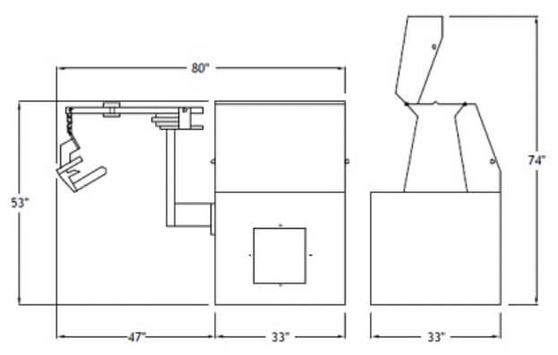
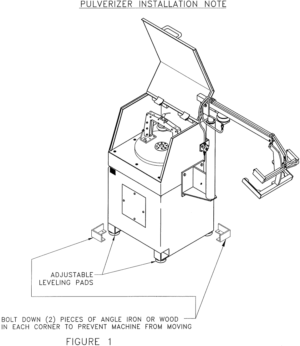
The pulverizer must be installed on a flat horizontal surface. Since the pulverizer is shipped without ballast in the base, no less than 450 lbs./200 kgs of ballast must be added in the form of lead slabs, grinding balls, scrap steel, rocks or similar material. DO NOT bolt the pulverizer on the floor. If the weight does not stop the machine from walking, bolt down angle irons or pieces of wood as per the attached drawing to prevent it from moving. Please note: the two front feet have adjustable bolts to allow levelling on uneven floor. Refer to Figure #1 for an illustration of how to install the pulverizer.
DO NOT OPERATE the pulverizer without ballast in the base to avoid severe rocking. This could happen, especially during start-up and slowing down of the machine, at the end of each grinding cycle.
During transportation, the vibratory body is secured with steel bolts and pipes at the base and the vibrating body. YOU MUST remove these items before operating the pulverizer.
The clamping system air regulator should be set to exceed 572-kilo pascals (90 psi) and no more than 620-kilo pascals (94 psi). The clamping system pressure switch is preset at 550-kilo pascals (90 psi). DO NOT exceed 94 psi or damage to the machine will occur.
However, should the pressure need to be adjusted, the silver screw on the pressure switch V082G (See Figure 6) is the one that regulates air pressure. The pressure switch is located inside the control panel and it is connected to the air valve via a brass tee. To increase pressure, turn it clockwise.
Also in the control panel there is a vacuum valve (V070E), which controls the airbag retraction. See Figure 5. With the air supply on, an airflow of 7-8 psi can be heard from the valve exiting it when the machine is not operating. At this pressure, the airbag will fully retract in 4-6 seconds. If the machine is not being used for a long period of time, turn the main airline supply off (V070B-Ball Valve).
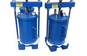
TM Pulverizers supplied with air hoist
The air hoist can be installed on either side of the machine. The air hoist regulator is factory preset for gentle lifting of the Grinding Barrel containing the grinding element and grinding media.
Should more lifting force be needed, pull out pressure regulator knob and turn it clockwise the needed amount, then push it back. Likewise, turn it counter-clockwise if too violent raising force is generated when the grinding barrel is lifted with the air hoist. The hoist arm has a screw at the rear end to adjust maximum lifting height should one want to pre-set it.
Electrical Connections
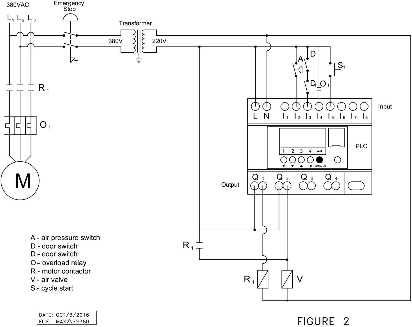
A wiring diagram of the electrical system of this pulverizer is attached. Refer to Figure 2.
The electric motor is usually wired according to the customer’s power supply. Also, a tag is attached indicating the voltage required.
Check the power available on the site to ensure that the pulverizer is connected to the correct voltage.
If your setup requires the motor cable to be on the opposite side of the machine, a hole has been provided for you to use. Remove the plug (V180) and re-run the cable through.
Changes in wiring must be made by a qualified electrician. HAVE THE ROTATION OF THE PULVERIZER MOTOR ACCORDING TO THE ARROW SHOWN ON THE MOTOR FAN COVER. The elliptical motion of the machine while in operation will tell you the motor rotation.
Maintenance
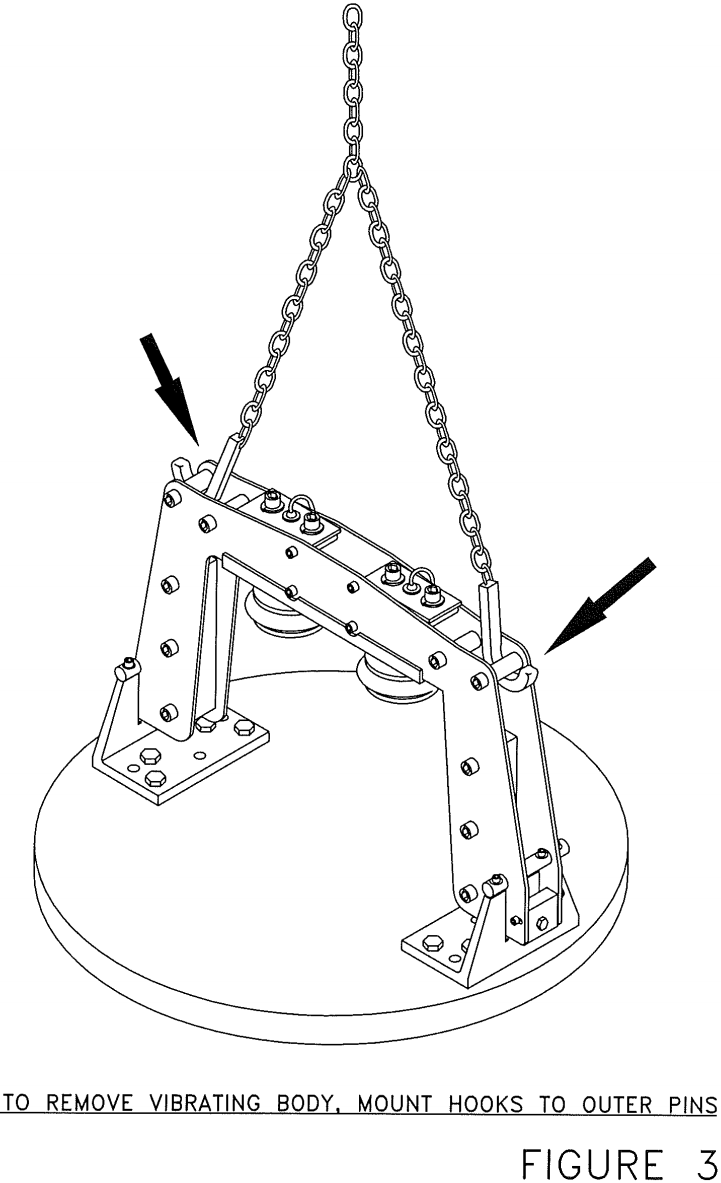
The motor bearings are factory lubricated. They need to be greased every 30 hours. One to two squirts of grease each nipple is sufficient. The PLC will display the word ‘GREASE’ when this operation is due. You need to press ESC and DEL simultaneously to reset the PLC and then continue your grinding process. If any need of maintenance/repair of motor, vibrating body, bridge, etc. arises, do the following: remove the top portion of the cabinet (which includes the door) and disconnect the motor cable from the panel and air line from the air bag. Attach two hooks or straps and carefully remove the vibrating body from the cabinet. Refer to Figure 3 for an illustration for removing the vibrating body.
Undo the bolts holding the motor to the vibrating body. Do the same for the motor flanges. If necessary, pry out the motor and motor flanges by screwing in the removed screws in the threaded holes at the flange’s periphery. The bearings have internal seals mounted in the steel housing removable after undoing two screws. Proceed with this operation and then it will be possible to remove bearings, inspect, clean, or replace, re-grease, and re-assemble.
Instructions for Installing Bearing on Electric Motor Shaft and Main Flange
Pack bearing with grease (Unirex N2L or Lubriplate 1200-2, or a similar grease). DO NOT overfill – the bearing should have half empty space when greased. Install it into main flange and mount cover plate. Repeat this procedure with the bottom end bell.
Place main flange upside down and press in the rotor shaft until bearing’s face butts against shoulder on motor’s shaft. Mount stator to main flange and then bottom end bell.
INSTRUCTIONS FOR CORRECTLY INSTALLING ECCENTRIC ON MOTOR SHAFT
- Place on the ground a ring or a couple of pieces of wood big enough and thick enough that the projection on the end bell on the bottom of the motor clears the ground.
- Make sure to place the eccentric on the shaft the way it was taken off. Set the eccentric on top of the motor shaft and lead the eccentric onto the shaft with the keyway in line with the key on the motor shaft. Hammer down on the eccentric making sure to give blows evenly around the eccentric bore. Tighten the set screw to hold the eccentric onto the shaft.
- At this point, place the vibrating body back onto the motor making sure that the motor electrical box is in position as to locate the motor wire through the frame in the proper direction. Re-tighten the screws to secure the motor to the vibrating body.
Failure to Follow this Procedure might cause Immediate Wear and Break Down of the Entire Motor
Operating Instructions
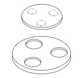
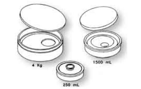
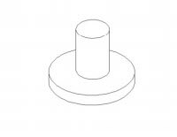
The 1kg, 2kg, and 4kg grinding barrels contains only one grinding saucer (disk). The 500mL grinding contains two grinding elements. The 250mL capacity grinding barrel contains three grinding elements: the solid centre cylinder and two concentric rings. The 100mL capacity grinding barrel contains two grinding elements: the solid centre cylinder and one customized ring. The material to be pulverized is poured between the rings in the 250mL grinding barrel and on top of the saucer/disk in the 1kg, 2kg, and 4kg grinding barrels.
In a situation where different combinations of grinding barrels are to be used, it is advised to experiment with different setup configurations in order to obtain optimal results. For example: placing two grinding barrels diagonally or side by side. CAUTION: Be sure to have the correct adaptor plunger when using different grinding barrel combinations in the machine.
The grinding barrel is placed on its seat. Then the hinged door(s) is closed over the moving part of the Pulverizer. The grinding time required to pulverize a certain mass of materials is set on the PLC timer prior to commencing the cycle. Pushing the touch pad start button will activate the air actuator which will lock the grinding barrel in its seat and then the motor will start (see Figure 6 for how to operate timer). The grinding cycle will also start.
The red push button is the emergency switch (V062E). When you press it, the motor will stop and the air pressure will be released.
Open the cover and remove the grinding barrel. When removing the grinding barrel with the air hoist, make sure to keep the lifting basket arm as horizontal as possible to prevent jamming of the grinding barrel in its seat. Usually the lid can be removed easily. However, if the lid is stuck to the barrel, a brass hammer or similar tool should be used to gently tap the underside of the protruding rim of the lid.
Brush of powder stuck to the grinding elements. Remove one element after the other while cleaning making sure that samples’ powder won’t be dispersed outside the bowl in the process.
Empty the contents of the barrel onto a TM stainless steel mixing tray, on glossy paper, on a sheet of rubber or similar material. Homogenize the sample by coning with two mixing trays, sub-sample by incremental division scoops for this procedure.
Grinding times depend on a number of factors:
- mass of material
- hardness
- particle size
- lubricating properties
Since the capacity of the grinding barrel is rated in mL rather than in grams, the mass of a sample will depend on its bulk density.
The volume of a sample may range from 100 mL up to 250 mL with 250 mL being the optimum capacity; for the 100 mL capacity grinding barrel the volume of the sample will be proportionally less, just as it will be proportionally more for the 1KG, 2KG or 4KG grinding barrel.
For soft materials such as coal, dolomite, etc. the maximum particle size of the feed can be as large as 15 mm. For hard materials such as pre-reduced iron ore, ferro alloys, etc. the top particle size should not exceed 5 mm.
Some soft materials such as talcum tend to lubricate the grinding elements. Others may form conglomerates of particles on the periphery of the barrel (caking) in a short time
Pulverize such materials in increments of 0.1 minute and check the fineness after each interval. If the required fineness cannot be obtained without caking, add 2 – 5 mL of ethanol freon solvent and pulverize for a time period that caused caking in dry condition plus 0.5 minutes.
Samples containing excessive amounts of moisture may also cake and should be dried before grinding.
AIR CLAMP
The machine control is set to retain air pressure in the clamping air bag for 8 seconds after termination of grinding cycle. This is necessary for safety reasons.
Instructions for Electrical Trouble Shooting
BEFORE SERVICING – DISCONNECT ELECTRICAL POWER
All components are at line voltage. Should the control panel fail to function, we recommend that a local qualified electrician be called. We invite you to have the electrician contact us should he have any problems in troubleshooting or obtaining parts to rectify the failure.
Important Note:
If installing a new replacement motor, make sure that the inside of the chamber underneath the vibrating body where the eccentric attached to the motor is mounted, is extremely CLEAN. This is imperative to prevent bearing failure as it is exposed to the chamber’s impurities.
DESCRIPTION OF PARTS FOR 4×1000 VIBRATORY RING PULVERIZERS
V001………………………………..Rubber feet for cabinet (4pcs.)
V002………………………………..Screws to retain front door (4pcs.)
V003………………………………..Cabinet front door
V004S………………………………Pulverizer cabinet
V005S-2……………………………Plate for Vibrating Body
V005A4KG………………………..Springs (6pcs.)
V005BZ-1………………………….Spring Guide for Vibrating Body (6pcs.)
V005BZ-2………………………….Spring guides for bottom plate (6pcs.)
V005CZ…………………………….Nut for Spring Guide (12pcs.)
V005FZ-1………………………….Rubber for stabilizers (3pcs)
V005GZ-2…………………………Clamps for stabilizers (6pcs)
V005HZ-1…………………………Clamp screws (12pcs)
V005JZ-1………………………….Top screw for Stabilizer (3pcs)
V005KZ-1………………………….Bottom screw for stabilizer (3pcs)
V005LZ…………………………….Screw for holding Rubber (6pcs)
V006………………………………..Screws for retaining plate of Vibrating Body (12pcs.)
V009K……………………………..Bolts to secure top cover
V009AK…………………………..Washer for V009K
V009BK…………………………..Lock Washer for V009K
V013K-2………………………….Hinge pin for doors (2pcs)
V014S……………………………..Top Doors
V017N-1…………………………..Lift-Up Handle (4pcs)
V018AY…………………………..Terminal Block
V018Y……………………………..Electrical Box & Cover for Motor
V019AKZ-1………………………208/220/240/440 volt Motor, 3 phase, 7.5HP
V019BKZ-1……………………….575 Volt Motor, 3 phase 7.5HP
V020Z……………………………..Screws to mount motor to vibrating Body (12pcs.)
V021Z………………………………Lock Washers for Screws (12pcs.)
V022Z………………………………Motor Key
V022CZ…………………………….Motor Bearing (2pcs.)
V022DZ…………………………….Inner Seal (2pcs.)
V022EZ…………………………….Seal Holder
V022FZ…………………………….Screws to hold Seal Holder (6pcs.)
V022GZ…………………………….Outer Seal (2pcs.)
V022HY…………………………….Fan Guard
V022HY-3………………………….Fan Cover Brackets (4 Sets)
V022JZ………………………………Motor Fan
V022LZ………………………………Fan Washer
V022MZ……………………………..Fan Lockwasher
V022NZ……………………………….Fan Screw
V022PZ………………………………..Motor Bottom Flange
V022RZ-1……………………………..Motor Top Flange
V022RZ-2…………………………….Motor Top Flange Insert
V022TZ………………………………..Motor Top Flange Cover
V022UZ……………………………….Screws for Motor Top Flange Cover (6pcs.)
V022VZ………………………………..Check Valve
V023ZX-4…………………………….Eccentric
V026S-3……………………………….Vibrating Body
V027A…………………………………..Locating Disk (4pcs)
V028-2………………………………….Dowel Pins (4pcs)
V028-3………………………………….Screws (12 pcs)
V028-4………………………………….Counter Sunk Allen Screws for Locating Disks (32pcs.)
V039B…………………………………..Flexible Connector (motor) (2 pcs.)
V039E……………………………………Base Plate for Wiring Box & Hardware
V159………………………………………Copper Grease Line
V160………………………………………Straight Brass Fitting
V161……………………………………….90deg Fitting
V162………………………………………Straight Fitting (3pcs)
V163………………………………………Vibrating Body Bearing
V164………………………………………Vibrating Body Seal
V165……………………………………….Vibrating Body Flange Cover
V166………………………………………..Screws (6pcs)
V167………………………………………..Grease Nipples (2pcs)
V168………………………………………..Screws (2pcs)
V169………………………………………..Aluminum Mounting Block
V171…………………………………………Grease Gun
V172………………………………………..Brass Fitting
V174-1……………………………………..Clamp and hardware (2 sets)
V175………………………………………..Grease line
V179………………………………………..Plug for side holes
V179A………………………………………Plug (Larger)
V179B………………………………………Nut for plug
4×1000 Clamp Assembly Parts
V030A-1……………………………….Clamping disk (4pcs)
V030B………………………………….O-ring
V030D-1……………………………….Screw (4pcs)
V030E-1……………………………….Clamp bar Hardware
V030S…………………………………..Air Bag (2pcs)
V032 90…………………………………Degree fitting
V032-1…………………………………..Tee Fitting
V033………………………………………¼” Air Clamp Hose
V033Y……………………………………Bolts for angle plate (8pcs)
V034S-1…………………………………Bridge for Clamping Assembly
V034A-1…………………………………Dowel Pins (6pcs)
V037Y7-4……………………………….Clamping Bar (2pcs)
V037T-2…………………………………Stabilizer Bar
V037U-2…………………………………Clamping disc (4pcs)
V037V-3…………………………………Clamping blocks (2 sets)
V070AB………………………………….Clamping plate and hardware
V070AC…………………………………..Hardware for clamp plate (2 sets)
V070R…………………………………….Bulkhead Coupling
V070X……………………………………..Male fitting (3pcs)
V088G…………………………………….Straight Fitting
V131………………………………………..Bridge Bottom Plate (2pcs)
V132K……………………………………..Bridge Frame (2pcs)
V133………………………………………Bolt for Bridge Frame (8pcs)
V134………………………………………Bolt for Bridge Frame (10pcs)
V135………………………………………Spacer for Bridge Frame (10pcs)
V136………………………………………Lockwasher (22pcs)
V137………………………………………Nut (18pcs)
V139………………………………………Screw to Hold Air Bag to Clamp (4 pcs)
V141……………………………………….Top Plate for Bridge Right
V141B……………………………………..Top Plate for Bridge Left
V142……………………………………….Spacer for Bridge Frame (8pcs)
V143……………………………………….Nut (8pcs)
V144……………………………………….Lockwasher for V143 (8pcs)
V145K……………………………………..Bridge Block (2pcs)
V146……………………………………….Screws for V148K (8pcs)
V147……………………………………….Lockwasher for V146 (8pcs)
V148K……………………………………….Round Bar (2pcs)
V149……………………………………….Washers & Nut (4pcs)
V150K……………………………………….Mounting Plate (4pcs)
V151K……………………………………….Re-enforcing tubing
V152……………………………………….Screw (4pcs)
V153K……………………………………….Screw & Hardware (2 sets)
V191……………………………………….Cable clamp (8pcs)
V191A……………………………………….Screw (8 pcs)
Optional
V177……………………………………………Dummy Spacer base
V177A………………………………………….Cap spacer for 250 ml bowls
V177B………………………………………….Cap spacer for 1000ml bowls
4×1000 CONTROL PANEL PARTS
*Need to specify what voltage machine is wired at when ordering
V061…………………..PUSH BUTTON START SWITCH
V062E………………..EMERGENCY STOP BUTTON
V063A-1……………..PLC CONTROLLER
V067…………………..MAGNETIC CONTACTOR BLOCK*
V068…………………..OVERLOAD*
V069…………………..TRANSFORMER
V070B…………………BALL VALVE
V070E…………………VACUUM VALVE
V070G…………………AIR SOLENOID VALVE
V070J………………….PIPE PLUG
V070K…………………RUBBER GASKET
V070N 90…………….DEGREE FITTING (2 PCS)
V070R…………………BULKHEAD COUPLING
V070S………………….DIN RAIL
V070U…………………REDUCER NIPPLE
V070X…………………..¼” MALE FITTING (4 PCS)
V070Y…………………..MANIFOLD
V070Z…………………..1/8″ MALE FITTING
V071B…………………..TERMINAL BOLT
V071C…………………..TERMINAL BLOCK (6PCS)
V071D…………………..TERMINAL BLOCK (2PCS)
V071E…………………..TERMINAL BLOCK (2PCS)
V071E-1…………………..TERMINAL BLOCK ENDS (2PCS)
V071H…………………..FUSE HOLDER (2PCS)
V071K…………………..FUSE (2PCS)
V071R…………………..PANEL BOX & COVER
V071T…………………..¼ TUBE TEE (QUICK DISCONNECT)
V073A…………………..ELECTRICAL CORD CONNECTOR (2PCS)
V073B…………………..WIRE CONNECTOR
V076…………………..SCREW/BRACKET TO HOLD WIRES (2 PCS)
V077…………………..SCREWS FOR TRANSFORMER
V077G…………………..CHECK VALVE
V082G…………………..PRESSURE SWITCH
V084G…………………..REGULATOR (2 PCS)
V085G…………………..GAUGE
V088G…………………..HEX NIPPLE (2PCS)
LIST OF GRINDING BARRELS
G-2-ND4KGML Grinding Barrel 4 kg, alloy-2, complete
G-1-ND4KGML Grinding Barrel 4 kg, alloy-1, complete
G-2-2KGML-1 Grinding Barrel 2 kg, alloy-2, complete
G-1-2KGML-1 Grinding Barrel 2 kg, alloy-1, complete
G-21500ML Grinding Barrel 1500mL, alloy-2, complete
G-11500ML Grinding Barrel 1500mL, alloy-1, complete
PS1400 Grinding Barrel, PS1400, carbon steel, complete
G-2-1KGML-1 Grinding Barrel 1 kg, alloy-2, complete
G-1 -1KGML-1 Grinding Barrel 1 kg, alloy-1, complete
G-21000ML Grinding Barrel 1000mL, alloy-2, complete
G-11000ML Grinding Barrel 1000mL, alloy-1, complete
G-2-500ML Grinding Barrel 500mL, alloy-2, complete
G-1-500ML Grinding Barrel 500mL, alloy-1, complete
G01-500ML Grinding Barrel 500mL, alloy-01, complete
GMS-500ML Grinding Barrel 500mL, Mild Steel, complete
G-2-250ML Grinding Barrel 250mL, alloy-2, complete
G-1-250ML Grinding Barrel 250mL, alloy-1, complete
G01-250ML Grinding Barrel 250mL, alloy-01, complete
GMS-250ML Grinding Barrel 250mL, Mild Steel, complete
GCS-250ML Grinding Barrel 250mL, Carbon Steel, complete
G-2-150ML Grinding Barrel 150mL, alloy-2, complete
G-1-150ML Grinding Barrel 150mL, alloy-1, complete
GCR-150ML Grinding Barrel 150mL, Ceramic, complete
GTC-150ML Grinding Barrel 150mL, Tungsten Carbide, complete
G-2-100ML Grinding Barrel 100mL, alloy-2, complete
G-1-100ML Grinding Barrel 100mL, alloy-1, complete
G01-100ML Grinding Barrel 100mL, alloy-01, complete
GMS-100ML Grinding Barrel 100mL, Mild Steel, complete
G-2–50ML Grinding Barrel 50mL, alloy-2, complete
G-1–50ML Grinding Barrel 50mL, alloy-1, complete
GMS–50ML Grinding Barrel 50mL, Mild Steel, complete
GCR–50ML Grinding Barrel 50mL, Ceramic, complete
GTC–50ML Grinding Barrel 50mL, Tungsten Carbide, complete
TRAY-50-1 Adapter Tray to hold 1 Grinding Barrel, 50mL
TRAY-50-3 Adapter Tray to hold 3 Grinding Barrels, 50mL
O’RINGS
V080A……………….O’Ring for Grinding Barrel, 4 kg
V081………………….O’Ring for Grinding Barrel, 1500mL
V081A………………..O’Ring for Grinding Barrel, 2kg
V081AA………………O’Ring for Grinding Barrel, 1 kg
V083…………………..O’Ring for Grinding Barrel, 500mL (and 1000mL lids made before Nov 2010)
V083A…………………O’Ring for Grinding Barrel, PS1400
V083B…………………O’Ring for Grinding Barrel, 1000mL
V084…………………..O’Ring for Grinding Barrel, 250mL
V085……………………O’Ring for Grinding Barrel, 150mL
V086……………………O’Ring for Grinding Barrel, 10OmL
V087…………………….O’Ring for Grinding Barrel, 50mL
V092……………………O’Ring for Grinding Barrel, Ceramic 150mL
V093…………………….O’Ring for Grinding Barrel, Ceramic 50mL
WHEN ORDERING ONLY PARTS OF A GRINDING BARREL, PLEASE SPECIFY BY USING THE TERMS BOWL, LID, LARGE RING, SMALL RING, PLUG OR DISC – WHICHEVER APPLIES FOR THE SIZE OF BARREL YOU REQUEST. Use the following extensions:
ML – Complete Grinding Barrel
BO – Bowl Only
LI – Lid Only
DK – Disk Only
LR – Large Ring Only
SR – Small Ring Only
PL – Plug Only
Examples:
G-2-250BO Bowl only, 250mL grinding barrel, alloy-2
GCR-50PL Plug only, 50mL, grinding barrel, ceramic
G-1-1KGML Complete 1 kg, grinding barrel, alloy-1


 HEAD / CHAMBER PULVERIZER - 911Metallurgist")
 HEAD / CHAMBER PULVERIZER - 911Metallurgist")