jaw crusher (1) zoom

Hover

high capacity & reduction ratio jaw crusher (11) zoom

Hover

high capacity & reduction ratio jaw crusher (12) zoom

Hover

high capacity & reduction ratio jaw crusher (13) zoom

Hover

high capacity & reduction ratio jaw crusher (14) zoom

Hover

high capacity & reduction ratio jaw crusher (15) zoom

Hover

high capacity & reduction ratio jaw crusher (18) zoom

Hover

jaw crusher (2) zoom

Hover

jaw crusher (3) zoom

Hover

jaw crusher (4) zoom

Hover

jaw crusher (1) zoom

Hover

jaw crusher (1)
high capacity & reduction ratio jaw crusher (11)
high capacity & reduction ratio jaw crusher (12)
high capacity & reduction ratio jaw crusher (13)
high capacity & reduction ratio jaw crusher (14)
high capacity & reduction ratio jaw crusher (15)
high capacity & reduction ratio jaw crusher (18)
jaw crusher (2)
jaw crusher (3)
jaw crusher (4)
jaw crusher (1)
Full Screen

5″ x 7″ High Reduction Ratio Jaw Crusher

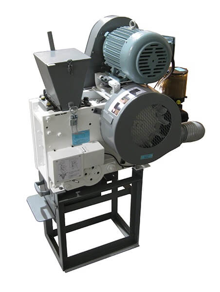
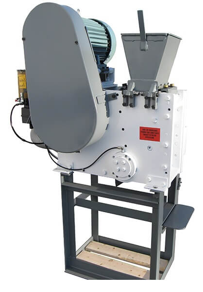
The 911MPE-TM-T is a Jaw Crushers for Coarse Primary Crushing and Mid Range Primary Crushing. This jaw crusher is equipped with a standard 5 HP motor and a 5″ X 7″ jaw cavity that will produce a discharge crushed product of under <1mm.

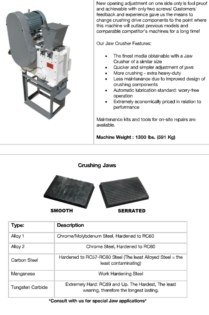
Well-proven single toggle, high reduction Jaw Crushers. The crushing capacity and the end-fineness of the sample material depend on the type of crusher and on the breaking characteristics of the sample material. Designed for laboratory applications and for operating environments and accepts soft to hard ores, drill cores, rocks, alloys, slags, soils, ceramics, and similar hard and brittle materials.canada manufacturer

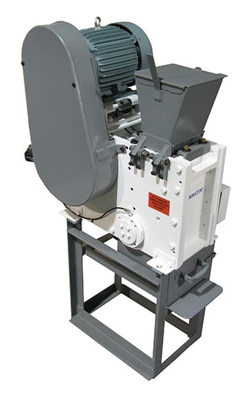
The Jaw Crusher 911MPE-TM-T is used for the rapid, effective crushing and pre-crushing of medium-hard, hard, brittle and tough materials. Its variety of materials offered, including heavy-metal free steel, its efficiency and safety makes it ideal for sample preparation in laboratories and industrial plants. For small amounts of sample the 911MPE-TM-T is used batchwise; for larger amounts it can be operated continuously. Control of the gap width and zero point adjustment allow for reproducible results.

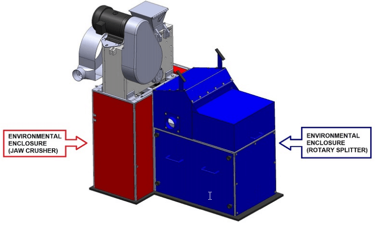
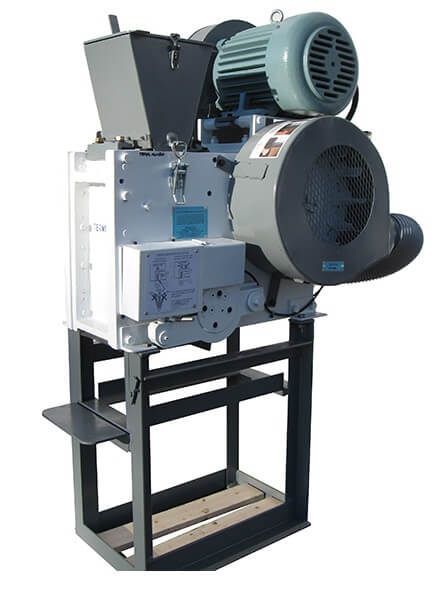
This performance jaw crusher can be inline unit (within your process) or stand-alone. With inline units we need to provide a control box, often also a different frame and inlet.  Depending on the application stand-alone units can also need a different frame and/or inlet.

test

Description

Thanks to the modular construction of housing and frame this jaw crusher is suitable for a wide range of applications. Jaw Crusher engineered for pre-crushing of extremely hard up to brittle materials.

  • Quick and easy to clean
  • Adjustable gap-setting
  • Easy exchange of jaw plates and side liners
  • Modular in-feed hopper:
    removable, with splashback protection, batch loader, or dosing plunger
  • External control box with start/stop
  • Powerful 3.7 kW- motor (Optional 5.6 kW)
  • Low installation height
  • Contamination free crushing
  • Specialty liners for your specific needs
high capacity & reduction ratio jaw crusher (14)high capacity & reduction ratio jaw crusher (15)


APPLICATION EXAMPLES

  • Minerals
  • ores
  • slags
  • cement & clinker
  • concrete
  • glass
  • borosilicate glass
  • ceramics
  • corundum
  • soil
  • drill core
  • industrial brittle waste
  • e-waste
  • sludges
  • Coal
  • Coke

ADVANTAGES

  • high crushing ratio
  • front door facilitates cleaning
  • infinite/continuous gap width setting
  • overload protection
  • wide range of materials for contamination free grinding
  • no-rebound custom feed hopper, removable
  • custom sample collector with safety switch
  • collecting receptacle with an outlet for continuous operation
  • connector for dust extraction
  • Quick and easy to clean
  • Adjustable gap-setting
  • Easy exchange of manganese jaw plates and side liners
  • External control box with start/stop
  • End-fineness: 1 mm
  • Powerful 5 HP motor (7.5 HP Optional)
  • Low installation height

Jaw Crusher is designed for batch or continuous pre-crushing of middle hard, hard brittle and tough materials for the following fine grinding.

Jaw Crusher Principle of Operation

The 911MPE-TM-T Jaw Crusher is used by laboratories and processing companies to crush solid materials such as rocks or soil and ores.
The material to be processed falls into the crushing chamber of the 911MPE-TM-T Crusher via a guide chute and is crushed by crushing action of a static and a dynamic jaw plate until it passes the pre-selected gap of the crusher.

Easy cleaning and operation

The 911MPE-TM-T jaw crusher can be used for small volumes batchwise or in a continuous mode for bigger volumes. You can easily change the movable and static jaw plates as well as the side liners.

Gap setting

The desired gap can set up easy and reproducible by spacer.

Possible Jaw plates / side liners material compositions

  • Hardened steel
  • Tungsten carbide
  • Heavy metal free steel
  • Stainless steel
  • Polyurethane & Ceramic
  • Aluminum alloys

Features and benefits

  • Better crushing performance due to 7500 Watt
  • Optimum crushing results
  • Easy adjustment of gap setting
  • CE certified
  • Removable infeed hopper
  • High precision solid steel underframe (available with castor wheels lockable)
  • Solid and spacious sample collector with castor wheels
  • Motor protection switch with start/stop
  • End-Product < 1 mm
  • Easy exchange of jaw plates and side liners

high performence jaw crusher

high performence jaw crusher

high performence jaw crusher

jaw crusher (2)jaw crusher (1)


jaw crusher (5)jaw crusher (4)
jaw crusher
jaw crusher

JAW CRUSHER Installers and Users

The AUTOLUBE system of this Jaw Crusher is programmed to be active for one minute every sixty minutes regardless of how many times you start and stop the machine!

To prevent your machine from trembling or moving from its set position, place the supplied rubber mat underneath it.

NOTE:

FOR SHIPPING PURPOSES THE JAW CRUSHER IS NOT MOUNTED ON THE STAND (if supplied with your order) LIFT IT UP WITH AN OVERHEAD CRANE AND HOOKS AS SHOWN BELOW:

Jaw Crusher Dust Collecting Hopper

If the dust collecting hopper was ordered, it should be installed between the bottom of the machine and stand, in the back, with the two (2) screws in the sides already in place. Remove the screws, insert them in the eyes of the hopper, and tighten.

One Year Limited Warranty

This Jaw Crusher is warrantied against defective materials or workmanship for one year from date of original purchase. This warranty is void if the product has been damaged by accident, unreasonable use, neglect, improper service, by not following the instructions in this owner’s manual, or other causes not arising out of defect in material or workmanship.

ATTENTION PURCHASER

ANY ALTERATIONS, RE-WIRING OR MODIFICATIONS TO BE DONE ON THIS MACHINE WHILE UNDER WARRANTY, MUST BE AUTHORIZED BY THE MANUFACTURER OTHERWISE ALL WARRANTIES BECOME VOID.

Jaw Crusher

Model #JCT#1AL

The lubrication system is set to grease the correct amount every 60 minutes irrespective of whether the machine is continuously operated or if it is stopped and started many times. Check regularly to refill it when the grease reservoir is at a very low level.

As grease, we recommend Lubriplate 1200-2 or any equivalent of the following heavy duty, non-corrosive extreme pressure, water resistant greases possibly containing molybdenum disulphides (N.L.G.I. No.2)

SKF – LGHB-2
Esso – Unirex EP2
Shell – Darina XLEP2
Chevron – Ultiplex grease EP2

NEVER, NEVER, NEVER SET JAWS TOUCHING EACH OTHER!

THIS MACHINE IS NOT SUITABLE FOR WET GRINDING. IT WILL CREATE SEIZING OF MATING PARTS AND POSSIBLE FAILURE OF BEARINGS AND OTHER PARTS.

The transparent purge lines will not show grease exiting from the machine simultaneously. That is, because there are different size cavities within the machine that will allow the grease to accumulate for a long time before it is eventually forced to come out.

The air deflector plate (JCT144G) with time might become obstructed with grease and rocks accumulation. It is advisable to detach the duct from fan cover to rear duct (JCT006A) and through the opening remove all the air flow obstructing material.

Should the clamp JCT095J, with time show slippage from the set position, that might be caused by grease that has percolated where it grips. By spraying paint thinner or similar solvent that dilutes the grease and blowing it away, this can be easily corrected. In the worse cases the clamp needs to be removed and cleaned along with the cover of the bottom shaft (JCT087A).

Also, when setting the opening with the moving jaw it is essential to have the moving jaw bottom edge, below the one of the stationary jaw. If the moving jaw bottom edge is set above the stationary bottom edge, under heavy crushing conditions, the jaws will have the tendency to open up.

If your machine is supplied with a dust enclosure, the recommended air suction for dust extraction is 150cfm, although variation may be needed upon the mass of dust produced. It is recommended to have an air regulating (Butterfly) valve installed, since it is highly unlikely a dust extraction system will generate the proper volume.

Instructions For Releasing Clamp

The clamp is released with the adjustment Lever (JCT095Y) shown to the right.

Jaw Crusher Clamp

Slide holed side of the adjustment bar (JCT133) on to the lever (JCT095Y) and pull it to release the clamp (JCT095J).

Jaw Crusher Adjustment Bar

Before adjusting jaws, the nut and bolt must be released entirely as shown in the image below.

Jaw Crusher Adjusting

The opening between jaws can then be adjusted to the desired amount using the adjustment key shown to the right.

Jaw Crusher Adjustment Key

when finished, release lever, and tighten the nut and bolt.

Parts Description – Jaw Crusher

(Quantities in brackets indicated quantity required per machine. When ordering please specify quantity required as all parts are priced each.)

JCT003 Motor Guard
JCT006 Flywheel/Fan Guard
JCT006A Duct from fan cover to rear duct
JCT007 Retaining screws for flywheel locking plate (2 pcs.)
JCT008 Locking screw for flywheel
JCT009 Locking plate for flywheel
JCT010 Retaining plate for flywheel
JCT011-1 Flywheel
JCT011A Screw to hold fan blade (10 pcs)
JCT011B Fan blade (10 pcs)
JCT011C Nut to hold fan blade (10 pcs)
JCT012 Retaining screws for flywheel locking plate (2 pcs.)
JCT013 Locking screw for flywheel
JCT014 Locking plate for flywheel
JCT015 Retaining plate for flywheel
JCT016-1 Drive pulley
JCT017 Key for drive pulley
JCT018 Lock nut for eccentric shaft
JCT019 Lock washer for eccentric shaft
JCT020 Key for flywheel
JCT021 Lock nut for eccentric shaft
JCT022 Lock washer for eccentric shaft
JCT023 Retaining screws for flange cover plate (4 pcs.)
JCT025 Felt for cover plate
JCT026 Ring for flange cover plate
JCT027 Bearing for main frame flange (hub)
JCT028 Felt for main frame flange (hub)
JCT030 Flange mounting screws (4 pcs.)
JCT031 Lock washer for flange mounting screws (4 pcs.)
JCT032 Flange for main frame excentric shaft. Stamped B.
JCT033B Spacing ring (Must be mounted with same flange where it was removed and with chamfer toward centre of shaft as shown). Stamped B.
JCT034 Retaining screws for flange cover plate (4 pcs.)
JCT036 Felt for cover plate
JCT037 Ring for flange cover plate
JCT038 Bearing for main frame flange (hub)
JCT039 Felt for main frame flange
JCT041 Flange mounting screws (4 pcs)
JCT042 Lock washer for flange mounting screws (4 pcs.)
JCT043 Flange for main frame excentric shaft. Stamped A.
JCT044A Spacing ring (Must be mounted with same flange where it was removed and with chamfer toward centre of shaft as shown). Stamped A.
JCT045 Bolts for pusher cover plate (6 pcs)
JCT046 Felt for pusher cover plate
JCT047 Pusher cover plate
JCT048 Pusher cover plate spacing ring
JCT049 Pusher bearing
JCT049A Pusher auxiliary bearing
JCT049C Bearing large spacer
JCT049D Bearing small spacer
JCT050 Screws for pusher cover plate (6 pcs)
JCT051 Felt for pusher cover plate
JCT052 Pusher cover plate
JCT053 Pusher cover plate spacing ring
JCT054 Pusher bearing
JCT054A Bearing small spacer
JCT055 Eccentric shaft
JCT057 Pusher (must be sold with JCT059)
JCT057A Barbed purge fitting (3 pcs)
JCT057B Clamp for purge line hose
JCT057C Purge line hose
JCT058 Screws for Pusher retaining cover (8 pcs)
JCT059 Pusher retaining covers (must be sold with JCT057) (2 pcs)
JCT062 Moving jaw top shaft
JCT062A Outer bearing (2 pcs)
JCT062B Middle bearing (2 pcs)
JCT062C Inner bearing (2 pcs)
JCT062D Ring for bottom shaft (2 pcs)
JCT062E Ring (grooves) for bottom shaft (2 pcs)
JCT063 Block (bearing housing) cover (2 pcs)
JCT063A Seal (2 pcs)
JCT063B Seal (Wiper) (2 pcs)
JCT063C O-Ring (2 pcs)
JCT063D Block cover screws (16 pcs)
JCT064A Clamp for purge line hose
JCT064B Purge line hose
JCT065 Moving jaw
JCT065A Moving jaw cover (2 pcs)
JCT065B Moving jaw cover screws (8 pcs total)
JCT065C Seal (2 pcs)
JCT065D Seal (Wiper) (2 pcs)
JCT065R Purge line hose
JCT065T Clamp for purge line hose
JCT065U Rubber curtain retainer screws (2 pcs)
JCT065V Rubber curtain retainer
JCT065W Rubber curtain JCT105
JCT066A Holding screws of moving jaw (2 pcs)
JCT067A Lockwasher for holding screws of moving jaws (2 pcs)
JCT069A Clamp for moving jaw JCT108
JCT077 Bottom shaft of moving jaw (pivoting shaft) JCT109
JCT077A Bottom shaft offset sleeve side A (must be purchased with JCT077B) JCT110
JCT077B Bottom shaft offset sleeve side B (must be purchased with JCT077B) JCT111
JCT079 Key for bottom shaft of moving jaw (2 pcs) JCT112 JCT113
JCT080-1 Housing for offset sleeve side A
JCT081A Cover for bottom shaft side A JCT114
JCT082 Screws to hold cover (4 pcs)
JCT086-1 Housing for offset sleeve side B JCT115
JCT087-1 Cover for bottom shaft side B JCT116
JCT088A Screws to hold cover for bottom shaft side B (2 pcs) JCT117 JCT118
JCT088-1 Screws to hold cover for bottom shaft side B (2 pcs) JCT119
JCT095A Pivot bar for adjusting mechanism JCT120
JCT095B Bolt and nut
JCT095C Threaded rod
JCT095D Washer for adjusting rod
JCT095E Nut for adjusting rod
JCT095F Screw
JCT095G Screw
JCT095H Lockwasher
JCT095J Adjustment holding clamp
JCT095K Dowel pin for guide block (4 pcs)
JCT095L Screws to hold guide blocks (2 pcs)
JCT095M Guide block (2 pcs)
JCT095N Clamp pivoting/sliding bar
JCT095P Hexagon capscrew to hold support plate (longer)(2 pcs)
JCT095N Flathead capscrew to hold support plate
JCT095T Support plate
JCT095U Dowel Pin
JCT095V Guard for adjustment holding clamp
JCT095W Screws to hold guard (2 pcs)
JCT095X Flat disc (washer)
JCT095Y Clamp releaser
JCT095Z Hexagon capscrew to hold support plate (shorter)
JCT105 Moving Jaw (serrated or smooth) Alloy 2
JCT106 Stationary Jaw (serrated or smooth) Alloy 2
JCT107 Clamp for stationary jaw
JCT108 Lockwashers for holding screws of stationary jaw clamp (2 pcs)
JCT109 Flat washers for holding screws (2 pcs)
JCT110 Holding screws for stationary jaw (2 pcs)
JCT111 Side wearing plate (left)
JCT112 Side wearing plate (right)
JCT113 Side wearing plate holding screws (2 pcs)
JCT114 Side wearing plate flat washers (2 pcs)
JCT115 Cotter pins (2 pcs)
JCT116 Motor plate shaft
JCT117 Motor plate
JCT118 Motor plate tensioner
JCT119 Retaining screw for motor plate tensioner to main frame
JCT120 Nut and washer for bolt retaining motor plate tensioner to main frame
JCT121 Bottom nut motor plate tensioner
JCT122 Bottom angular retaining spacer
JCT122A Upper angular retaining spacer
JCT123A Top angular retaining spacer (2 pcs.)
JCT124 Top nut of motor plate tensioner
JCT125 Hopper
JCT126 Hopper main frame side clamp
JCT127 Hopper cover clamp
JCT130 Drawer
JCT131 Stand
JCT132A Wrench
JCT132B Adjustment key
JCT133 Bar for Adjustment key
JCT134 Cover for bearing flange of main frame eccentric shaft
JCT138 Lockwashers for pusher cover (8 pcs)
JCT139 Belts (specify 50 or 60 hertz, 5 or 7.5HP motor) (2 pcs)
JCT143-1 Front part of JCT frame
JCT143A Bar with rubber and hardware
JCT144 Back part of JCT frame
JCT144B Washer for autolube mounting frame (2 pcs)
JCT144C Screw for autolube mounting frame (2 pcs)
JCT144D Auto lube mounting frame
JCT144E Screws and washers to hold duct (4 pcs)
JCT144F Duct inlet
JCT144G Air deflector plate (Vent)
JCT145-2 Left side of JCT frame
JCT145E Motor mounting plate’s yoke
JCT145F Motor mounting plate’s yoke screw
JCT145G Motor mounting plate’s yoke hardware
JCT145J Support plate hardware (2 pcs)
JCT145K Support plate
JCT146-2 Right side of JCT frame
JCT146A Insert for right side of frame
JCT146B Screws for insert (2 pcs)
JCT146C Dowel pins for insert (2 pcs)
JCT146D Screws to hold strip (8 pcs)
JCT146E Strip for holding side wearing plate (2pcs)
JCT148A Seals (2 pcs)
JCT151 Nuts for hopper bolts (4 pcs)
JCT152 Hopper bolts (2 pcs)
JCT153 Hinge brackets for hopper (4 pcs)
JCT154 Lockwashers for hopper brackets (8 pcs)
JCT155 Screws for hopper hinge brackets (8 pcs)
JCT157 Screws for hopper main frame side clamp (3 pcs)
JCT158 Frame/Leg screws (18 pcs)
JCT158-2 Sockethead screws (2 pcs)
JCT159 Lockwashers for frame/leg screws (22 pcs)
JCT160 Frame legs (4 pcs). If ordering please specify front right (F.R.) front left (F.L), rear right (R.R.), rear left(R.L.)
JCT161 Dowel pins for frame (8 pcs)
JCT162 Cross bars (2 pcs)
JCT165 Motor
JCT165A Motor shaft key
JCT165B Rock shield
JCT173 Frame Leg Screw (4 pcs)
JCT174 Screw for Stand (4 pcs)
JCT175 Rubber pad (4 pcs)
JCT176 Nylock Nut (4 pcs)
JCT188 Cover for bearing flange of main frame eccentric shaft
JCT238 Protective rubber rings for grease line (2 pcs)
JCT280 Pulley (specify 50 or 60 hertz)
JCT281 Bushing (specify 50 or 60 hertz)
JCT351 Seal for offset sleeve side A and B Housing (2 pcs)
JCT352 Seal for bottom shaft side B cover
JCT374A Bar for Rubber (short hoppers)
JCT374B Lockwasher
JCT374C Screw
JCT374D Bar for Rubber (tall hoppers)
JCT374-S Rubber strips (short hoppers)
JCT374-T Rubber strips (tall hoppers)
JC-MAT Rubber Mat
JCBAL2-1 Screw (6pcs)
JCBAL4-1 Washer (6pcs)
JCBAL9ABalancing block flywheel side
JCBAL9B Balancing block Pulley side

Parts Description – Autolubrication System

(Quantities in brackets indicated quantity required per machine. When ordering please specify quantity required as all parts are priced each.)

JCT057A Barbed purge fitting (3 pcs.)
JCT057B Clamp for purge line hose
JCT064A Clamp for purge line hose
JCT064B Purge line hose
JCT065R Purge line hose
JCT065T Clamp for purge line hose
JCT230A Straight grease fitting (8 pcs.)
JCT230B Fitting for main grease line
JCT231A Check valve (3 pcs.)
JCT233 Screws to fit manifold to Jaw Crusher (2 pcs.)
JCT234 Fitting for main grease line to nmanifold
JCT235 Fitting for main grease line to manifold
JCT237 Lock washer for screw to hold manifold to Jaw Crusher (2 pcs.)
JCT239A-1 Electric motor
JCT240A 90 degree grease fitting (12 pcs.)
JCT258 Grease unit main frame
JCT260-4 Connector, wiring and plug
JCT264 Straight adaptor for pipe
JCT265-1 Control panel box
JCT266 Grease line from one point lubrication to manifold
JCT267 ¼” pipe adaptor
JCT271A Pump speed reducer (sold only together with JCT239A-1)
JCT272-1 Grease container
JCT272-2 Screw (4pcs)
JCT275-2 Cap (top part)
JCT275-3 Cap (bottom part)
JCT275-4 Screw (3pcs)
JCT273A Grease pump primer nipple
JCT276A Pressure check valve
JCT279 Tube Compression Ring
JCT282 Double Cone Compression Ring
JCT288 ½” Non-metallic clamp for cable
JCT289 ¾” Non-metallic clamp for cable (2 pcs)
JCT292 Transformer for autolube
JCT295-1 Grease Manifold
JCT295A Grease Fitting (10pcs)
JCT315 Grease Line
JCT316 Grease Line
JCT317 Grease Line
JCT318 Grease Line
JCT319 Grease Line
JCT320 Grease Line
JCT321 Grease Line
JCT322 Grease Line
JCT323 Grease Line
JCT324 Grease Line
JCT350 Grease pump bleeder screw
JCT350-1 Grease pump bleeder screw larger
JCT353-1 Lubricator Housing
JCT353B Bottom cover plate
JCT353C Screw (12pcs)
JCT353D Side cover
JCT353E 90 Degree connector and cable
JCT353F Inner cover plate
JCT353G Clear cover plate
JCT353H Screw (8pcs)
JCT353J Screw (6pcs)
JCT353K Drain plug
JCT353L Screw (3pcs)
JCT354 Metal Sensor and hardware
JCT356-2 Lubrication Monitor
JCT357 Bridge Rectifier

Jaw Crusher Terminator 2


Jaw Crusher Automatic Lubrication Motor 1

Jaw Crusher Auto Lube

Jaw Crusher Auto Lube Operating

Disassembling/Assembling

To remove the motor (JCT165):

  1. Remove motor guard (JCT003).
  2. Release tensioned belts by undoing nuts on motor plate tensioner (JCT118).
  3. Remove belts (JCT139).
  4. Remove motor (JCT165) by undoing bolts holding it to motor plate (JCT117).

Removing flywheel (JCT011) (same procedure for drive pulley (JCT016)):

  1. Remove flywheel guard (JCT006).
  2. Open up locking plate lips (JCT009) for all screws (JCT007 & JCT008).
  3. Remove screw (JCT008), loosen up screws (JCT007) enough to allow insertion of a small plate and a ½” NC nut between the retaining plate of flywheel and the flywheel itself. Use a ½” bolt screwed in the nut through the hole in the retaining plate (JCT010) to force out the flywheel from the main excentric shaft (JCT055).

Disconnecting the pusher (JCT057) from the moving jaw (JCT065):

  1. Remove grinding jaws (JCT105/106).
  2. The moving jaw (JCT065) has the appropriate holes in the face for one to insert a ½” socket wrench and allen drive to start undoing bolts (JCT058). Afterwards, a bondus socket wrench in combination with a ratchet will speed up the process considerably (see Picture #1).

Moving jaw (JCT065) removal:

  1. To remove moving jaw from the machine, remove cover (JCT081A) by undoing screws (JCT082) with a normal socket wrench and pipe (see picture #2).
  2. Fasten the extractor/offset hub puller across offset sleeve (JCT077A) by using the threaded holes in the face (see Note 1). The bar will have two threaded holes ½” NC in line with the ones used, clearing the hub’s diameter. Now one can thread two bolts through the bar against the JC frame and pull out the hub. Make sure also to remove the pivoting shaft key (JCT079). By loosening the adjustment clamp one can now slide out the bottom shaft from the machine and remove the moving jaw.
  3. To pull out bottom shaft (JCT077) from cover (JCT087-1), first remove the two screws (JCT088A) and two screws (JCT088-1) from it. Then screw in two through the cover on the shaft’s face with at least ½” thread into the shaft and clearance of ½” between cover and screw’s head. Make sure that screws are protruding from cover’s surface at least the same amount. Set shaft vertically with cover up supported at the lower edge. If a press is available press down on the screw’s head that had previously been mounted on the shaft’s end. Otherwise, by using the same set up and a flat plate set onto the screw’s head, hammer them down thereby freeing the cover from the shaft.
  4. Now using a similar method one can press out the shaft from the offset sleeve.

Disassembling the moving jaw (JCT065):

  1. All bearings, top and bottom, are precision pressed in line into the moving jaw. The same procedure will be used to press them out.
  2. To replace old ones with new ones, proceed by pressing the top ones into the seats, one on each side and at the bottom two from each side.

Removing the pusher (JCT057):

  1. Prying out the frame’s insert (JCT146A) will greatly facilitate the pusher removal. Therefore, first remove flange A (JCT043) and then undo screws (JCT030) from flange B (JCT032). (See Note 1.) The insert will come out by:
    1) Removing support plate (JCT145K) by removing screws (JCT145J & JCT145F).
    2) Insert two round bars (½” diameter by 2-3/8″ long) into threaded holes ¾” NC on part JCT146A (see Picture #3)
    3) Screw in ¾” minimum thread screws. (For this purpose, custom made bolts are available from the factory without the need of ½” dia. x 2-3/8″ bars. Also read Note 1.) This will pry out the insert. Now the pusher can slide out from JC frame.

Pusher (JCT057) disassembling:

  1. Set the excentric shaft (JCT055) vertically and supports under cover side A. The shaft can be pressed out all the way since it has no shoulders. Remove covers. Press out first bearing on side A. Rotate pusher. Use a bar slightly smaller than the big diameter of the center’s bearing inner ring and press out side B bearing. Central bearing will be removed by pressing onto the bearing roller.
  2. Flange A (JCT043) and B (JCT032) are conventional bearing housings: If bearing replacement is necessary press them out, replace and re-pack with grease. At the reassembling stage, two important things to keep in mind:
    1) Reassemble pusher and press onto it excentric shaft (JCT055) and also flange B (JCT032). Slide assemblies into JC frame. Fasten flange B to frame with two 3/8″ NC bolts. This allows one to mount flange A on the opposite side in an easy manner, particularly when one has two longer 3/8″ NC bolts that will drive the flange into the frame’s seat. (See Note #1).
    2) The moving jaw must be re-assembled (if bearing replacement was needed) before being re-assembled into the JC. Being a relatively heavy piece some auxiliary lifting device might be necessary to lower it within the frame. All machines purchased and delivered before May 31, 2004 had been equipped with a sealing system made of parts JCT148, 149, & 150. After that date, a new improved seal (JCT148A) has been installed and it is fully interchangeable with all previous machines and is available for replacement. When replacing seals, first slide them onto covers (JCT065A) and then proceed in lowering the moving jaw within the JC frame until it has the lower bearing’s hole in line with housing’s 077B, 087, & 088 will be slid through the bearings and secured tightly with clamp (JC095J). Now, one can insert key (JCT079) onto the bottom shaft on the opposite side and by using a plastic mallet, hammer into place offset sleeve (JCT077A). Please note that in order to have the bottom shaft staying in place rigidly when assembling this offset sleeve it is sufficient to tighten the adjustment clamp on the opposite side.

Pusher installation and positioning:

  1. With everything bolted in place, that is, insert (JCT146A) and flanges (JCT032 & JCT043) it is very important to tighten first locknut (JCT018) on side A and then the locknut (JCT019) on side B. In both processes, it is advisable to screw on old ½” NC hexagon head bolt, preferably with same heavy duty washers, in between at the opposite end of the excentric shaft and hammer onto it while tightening the locknuts. One will notice the shaft’s lateral displacement until it will no longer happen and therefore the shaft will be correctly positioned.

Note 1

Two customized accessory kits are available that will facilitate enormously the disassembling/assembling of this machine.

Kit One: – Extractor/offset hub puller
– Moving jaw lifting bridge
– Insert extractor screws (2 pes.)
– 3/8″ Ball point socket wrench
– 3/8″ hexagon socket drive

Kit Two: All items in Kit One plus:
– Disk to remove spherical roller bearings in pusher
– Disk to press in pusher’s bearings
– Disk to press in & out moving jaw bottom bearings
– Riser to support moving jaw to press in or out bottom shaft bearings
– Disk to remove bearings (bushings) in top of moving jaw
– Bar to press in & out rings for bottom shaft
– Disk to press bearings into flanges A & B
– Disk to press bearings (bushings) in top of moving jaw in their seat

Jaw Crusher Disassembling Assembling

Jaw Crusher Disassembling Assembling 2

Jaw Crusher Disassembling Assembling 3

Autolubrication System Maintenance and Troubleshooting Information

Pump Features:

Number of Devices Involved in the Pumping Process: From 1 to 3
Discharge/Cycle with Adjustable Pumping Element: 0.01 – 0.16 cc
RPM: 22
Motor: 24 V dc – 30 W – 1.5 A
Reservoir Capacity: 2 kg
Maximum Working Pressure: 275BAR (3993 PSI)
Recommended Lubricants: Grease Max. NLGI – 2
Temperature: From -20°C to +80°C
Discharge Outlet: ¼”G

Overall Dimensions (in millimetres):

Jaw Crusher Dimension

Single Line Progressive Dividers DPM Features:

Discharge/Stroke: 0.10cc – 0.15cc – 0.20cc
Operating Pressure: From 15 bar to 275 bar
Operating Temperature: From -20°C to +80°C
Body Distributor: Galvanized Steel
Number of Cycles/Minute: Maximum 250
Inlet: 1/8″
Outlet: M10x1
Mounting Screws: M5x40
Lubricants: Grease Max. NLGI – 2
Control Elements: Visual and Electric for Cycle and Overpressure indication
Main Lines: Tube O.D. 10-8-6
Secondary Lines: Tube O.D. 6-4

Overall Dimensions (in millimetres):

Jaw Crusher Over Dimension

Single Line Progressive Dividers Flow Diagram:

Operating Sequence

  1. Pressure supply through internal passages moves piston “A” left while holding pistons “B” and “C” fixed. A measured quantity of grease discharges from Outlet 4.
  2. Piston “A” reaches end of stroke. It opens internal passages directing pressure supply to right end of piston “B”. Grease discharges from Outlet 1.
  3. Piston “B” reaches end of stroke. It opens internal passages directing pressure supply to right end of piston “C”. Grease discharges from Outlet 2.
  4. Piston “C” reaches end of stroke. It opens internal passages directing pressure supply to left and end of piston “A” which returns on its initial position as grease discharges from Outlet 3.

Black – Pressure supply acting

Jaw Crusher Pressure Supply

Jaw Crusher Pressure Supply 2

Jaw Crusher Pressure Supply 3

Jaw Crusher Pressure Supply 4

Dots – Grease being dispensed to bearing
White – Static, no pressure

Layout of Centralized Lubrication System with Single Block Progressive DPM Series

Jaw Crusher Control Panel

Starting Up the System

  1. Fill the grease lines with clean grease. An air driven pump works well for filling long grease lines. Fill the discharge line from the valve manifold to the bearings and also lubricate the bearings with a hand grease gun if possible.
  2. Fill the reservoir with clean grease.
  3. Loosen the grease lines at all valve manifold inlet outlets as well as at bearing injection points.
  4. Before starting the motor, check the following:
    ♦ System power requirements – voltage, phase, AC or DC, etc.
  5. Start up the system pump and progressively purge all parts of the system of air. Tighten the inlet fitting at the primary valve manifold. When the pump to the primary valve manifold line is free of air, repeat the operation at the bearing injection points.
  6. After the system has run for a while, check all connections for leaks.
  7. Observe normal system operating pressure, check if there is any excessive pressure peaks or dips which may indicate a tight bearing or valve manifold being distorted in mounting, or a loose or disconnected fitting.

To check if the auto lubrication system is functional

  1. Simply disconnect main grease line (235) from the grease reservoir or manifold and let the machine operate for more than one hour. There will be a teaspoon of grease protruding from the opening.
  2. Be aware that the pump operates only one minute every hour regardless how many times one starts and stops the machine. Therefore, if ever circumstances arise where there is doubt that the lubrication occurs, repeat the above operation to ascertain the situation.

How to Prevent Problems:

  1. Keep reservoir filled. A pump operating with an empty reservoir may force air into the system causing difficulty in building pressure or preventing the pump from priming.
  2. Use clean grease because foreign matter may clog pump filler screen. Keep filler screen and filler connection assembly clean.
  3. Inspect entire system regularly including all grease lines. Replace if damaged. Connections should be tight and a small amount of grease should be at the edge of each bearing.

How to Locate and Correct Problems:

  1. If there is air in the reservoir it is likely because the pump fails to build pressure. Correct this by cleaning out reservoir, adding a small amount of oil (this helps prime and purge system of air), and filling it with clean grease. To ensure that the system is free of air, cycle it several times and then open the lines at the valve manifold inlet outlets to bleed out the air.
    Note:
    Remember that a fully pressurized grease system capable of operating properly is conditional to having removed all air and filled it with grease!
  2. Locate blocked points as follows:
    A. Open the pressure line at the inlet outlet to the manifold to check for blockage of the line to this point with pump operating. Grease should flow without the pressure opening the pressure check valve and releasing grease.
    B. Disconnect lines in an alternative sequence at the manifold. Grease should eject from each of the discharge outlets. If any of the outlets does not let out grease, the manifold is not functioning.
    C. If the manifold is O.K., reconnect the grease lines and check at the bearing connections that grease reaches them. With a manual grease gun and a grease nipple one can check each passage at the bearing grease outlets that there is no blockage causing the grease not to flow. If all checks out O.K., reconnect all lines and start the autolube system.

If the Autolube System Operates but does not pump grease:

Jaw Crusher Cause Solution Repair

Pump Operates but Unable to Build Pressure or Operate System:

Jaw Crusher Cause Solution Repair 2

Other Possible Problems:

Jaw Crusher Other Possible Problem

Autolube – Troubleshooting Wiring Connections

If the autolube system is not operational, it is possible that there is a wiring connectivity issue. Test wiring for continuity as shown in the steps below:

First remove the bottom cover plate from the autolube system (JCT353B). With the cover removed, unplug the motor cable connector as shown.

Jaw Crusher Wiring

Start by testing the cable connector on the side that leads to the motor. The two white wires on the end need to be checked for continuity as shown below. If there is continuity between these wires, this connection is not the cause of the issue. Proceed to the next step.

Jaw Crusher Wiring Connection

Next test the connections on the corresponding cable connector that leads out the side of the autolube housing. Both of these wires need to be checked for continuity. See pictured below:

Jaw Crusher Test the Connection

If testing is successful proceed to the next step.

Next test the cable that leads from the autolube system to the control panel. The two wires that need to be checked for continuity are the White (7) and green (6). See pictured below.

Jaw Crusher Control Panel 2

If all of the previous tests are successful, the last connection to check is the one at the PLC. Open the control panel and confirm that the white wire shown below is properly connected to the 12 port in the top of the PLC controller.

Jaw Crusher PLC Controller

If all of the wires covered in this instruction set are tested successfully, it is likely that the PLC controller is faulty.

jaw crusher dimensionsjaw crusher dimensions. side view
jaw crusher dimensions top view

jaw crusher dimensions front view
Jaw Crusher Dimensions front view
I Need Assistance