Table of Contents
- Safety
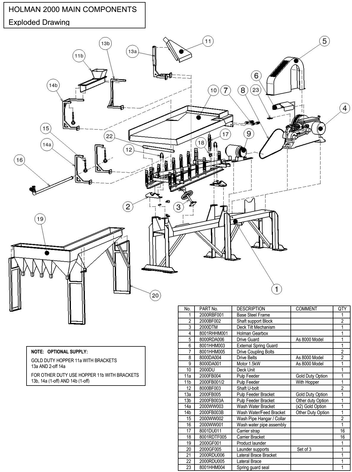
- Bill of Materials Shipped
- Unpacking
- Table Installation & Assembly
- Launders
- Feed Box / Wash water Bar
- Pre-Start up Checks
- Holman 2000 Operation
- Holman Head Motion
Safety
- Lift Table unit using minimum 1.5 tonnes lifting equipment
- Use marked balanced lifting points
- Ensure drive is isolated before guard removal
- Ensure unit is firmly fixed to level floor before operation, and all support steelwork is fully tightened
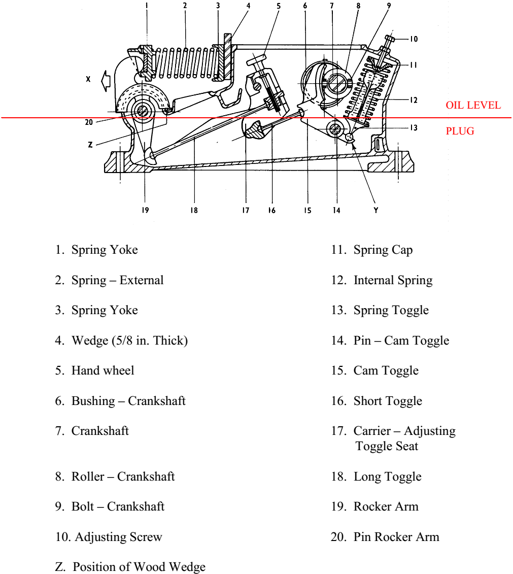
- Ensure drive is OIL filled to correct level (level plug on back of casing) prior to operation
Do not install against a wall or close to other machinery thus reducing operator access around the machine. We recommend 1 metre clearance from all equipment extremities (refer GA drawing W165 of assembled unit)
Do not allow ancillary equipment to come into contact with the moving deck since this will cause increased wear and possible failure of the deck.
Do not install equipment where visible inspection of the separation on the decks is prohibited.
Do ensure that installation area is well lit – for monitoring of mineral separation.
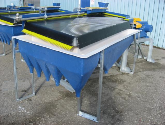
Model 2000 can be shipped fully assembled ready for positioning and bolting down. Final installation of the main product launder with steel support is all that is required.
In this case ignore unpacking/assembly instructions in sections 3, 4 & 6
Bill of Materials Shipped
- One table deck with drive connection plate fitted.
- GRP launder and three galvanised steel stands
- Main galvanised frame complete with head motion assembly / motor drive
- Tilt frame complete with bearing locations (2 off) and carrier brackets pre fitted (16 off).
- Tilt screw with mounting brackets.
- Table feed box.
- Wash water pipe (stainless).
- Set of wash water/table feed box brackets (3 off)
- Box containing deck carrier straps (16 off). (Complete with yellow rectangular washers and fixings)
- Lateral brace (timber)
- All necessary fastenings for assembly.
Unpacking
All table components are in a wooden packing case having a loose lid and front panel. Unscrew and remove the lid of the case first, then the front panel. Unpacking and assembly should if possible, be made at the place the table will be in operation. Unpack in the following order: –
Remove the deck and store on the backboard in a vertical position.
Remove the GRP launder.
Remove all loose packages
Remove the main frame complete with head motion assembly (approx 500kg)
Remove deck tilt-frame assembly.
Table Installation & Assembly
General
Referring to GA drawing W382 (fully assembled Holman 2000) – we recommend 1 metre clearance working area from all equipment edges.
Loosely fit all bolts until assembly is complete unless otherwise stated.
Proceed as follows:
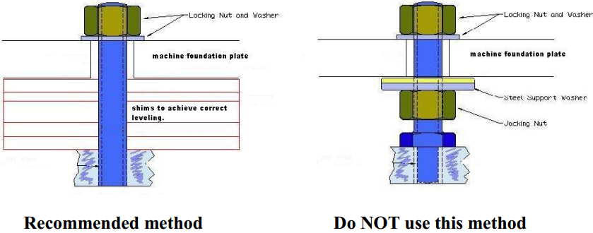
- Install main frame in its permanent position referring to drawing W174, showing foundation locations. Drill and bolt down with M20 x 250mm long high tensile resin anchor bolts (concrete base) or M20 high tensile fasteners (steel structures). Use flat face shims beneath anchor points for levelling of base, do not leave supported on jacking nuts. (See diagrams below)
Foundation bolt installation guidance
- Offer the tilt frame – preferably using overhead slings and locate to four off bolt locations (M16 x50) on the base steels support brackets (refer pictures). Tighten to ~100Nm torque.

- Ensure orientation with lateral brace bracket on deck underside is positioned at concentrate end.
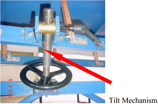
- Attach tilt screw handwheel assembly picture above to base and tilt frame using additional 2 off M10 x 30 bolts to tilt frame. Bolts on the base frame are already in position (M10 x 25 4 off).
- Visually level the tilt frame using the handwheel.
- Select deck and fit 16 off-deck carrier straps (- use one backing plate per carrier). Ensure straps are fitted to the M8 x 70 bolts, pre-fitted to the deck.
- Suspend deck over tilt frame using slings, position, and connect all 16 x straps to carrier brackets (M8 x 25 bolts – one backing plate per carrier). Tighten bolts.
- Remove the drive external spring guard (and white rubber surround seal)

- Couple draw-head plate to head motion using 2 off M20 x 180 square head coupling bolts, pre-fitted to the gearbox, and loosely tighten.
- Select lateral brace (timber) and position to tilt frame bracket & to locating bracket on tailings edge of deck underside. Fix using 2 off M10 x 40 bolts and backing plates.
Alignment
- Adjust draw head coupling bolts evenly to allow carrier straps top end to be approximately vertical.
- The carrier straps should be in line with each other when viewed along the length of the table.
NOW TIGHTEN ALL FIXING / ASSEMBLY FASTENERS INCLUDING THE HEAD COUPLING BOLTS, and carrier strap bolts. REFIT THE EXTERNAL SPRING GUARD AND RUBBER SAFETY SEAL.
Launders
- Position launder stands and launder conveniently to collect table deck discharge.
- Mark launder fixing points and drill launder (8mm) as required. Fix launder to support stands using M10 x 40 bolts (supplied). Bolt the 3 stands to the floor using M12 floor fixings (not supplied)
Feed Box / Wash water Bar
Three off Support Brackets are supplied for the feed box and wash water bar. All are fixed to the main channel using M10 x 40 bolts (supplied), to the three sets of pre-drilled holes on the main channel.
- Select larger twin arm bracket and mount to central locating holes on main channel
- Select straight bracket and mount at concentrate end-locating holes.
- Remaining bracket is fastened at drive end locating holes.
- [An optional special support bracket for use with “Gold” feed distributor may be supplied.]
- Standard GRP Feed box is attached to its support bracket using M10 x 40 bolts, with hopper to drive end.
- Wash water bar is attached to its support brackets (using M12 x 150 threaded bolts), with valve at concentrate end, and discharge holes to top.
Table assembly is now complete, Refer to Technical Specifications & Section 8.0 Operating Instructions for further information, and for electrical and water connection requirements, but please note the following:
Pre-Start up Checks
- With machine electrically isolated, and head motion drive belts removed, rotate drive pulley by hand 3-4 times to ensure all movement is free and secure.
- Check electrical motor rotation direction (as per Operation Instructions)
- Connect drive belts and replace pulley guards.
- Ensure head motion is filled with appropriate oil, and level checked prior to operation (approx. 11 litres) of good grade 20W/50 automotive oil (oil leval plug on the back of the head motion).
Holman 2000 Operation
The capacity and selectivity of the Holman Concentrating Table is largely due to the motion imparted by the vibrator. The mechanism is totally enclosed, practically noiseless and runs in oil. Ordinary wear and lost motion is taken up by two springs, and a different stroke characteristic is obtained by reversing the direction of rotation. The vibrator is normally driven by a T.E.F.C. electric motor through vee belts.
Normal rotation (viewed from pulley side) should be clockwise. However, in certain specific cases better results are obtained by reversing the direction of rotation.
A pulley speed between 270 and 280 rev/min is recommended. It is inadvisable to operate at speeds exceeding 290 rpm as ‘bounce’ of the internal spring will occur leading to increased internal wear.
Feed
In general practice the proportion of solids in the feed should be from 20% to 30% w/w solids, and in no case exceed 35%. The percentage of solids, which, after overall adjustment, is found to give the highest extraction rate, should be maintained.
Quantity of feed also requires careful attention. Constant feed rate (tph) of solids/water results in more consistent separation.
Variations in the characteristics of the feed ores being treated on the tables will affect capacity. As a general guide and based on low (<20%) proportions of the heavy value minerals in the feed, if feed particle sizes are nominally lower than 100 microns, capacities of ~ <150KG/HOUR are possible. With feed particle sizes nominally >250 microns, capacities of ~450KG/HOUR are possible.
It is only by vanning or assaying the products over a trial period following each adjustment that the optimum capacity can be determined. The overloading of tables decreases efficiency; therefore it is more economical to install additional units than to try and obtain greater output by increasing the feed beyond the maximum for effective operation.
The capacity of a table is also governed by the particle distribution of the feed material, the percentage and relative differences in the mineral specific densities in the feed and the ratio of concentration desired.
Stokes Law of “Equivalent” particle diameters applies and Holman-Wilfley has many years experience in advising on the appropriate feed sizing for different applications.
As a general rule, the lower the differences in mineral specific gravities being separated, the closer the particle size distribution of the feed required.
Stroke
Stroke characteristics play an important part in concentration – coarse material usually requiring a longer stroke than fine material. The adjustment of stroke may be made by taking off the inspection cover and rotating the handwheel clockwise to shorten, and anti-clockwise to lengthen the stroke.
Machines are normally set at mid-stroke (~12mm) at supply.
Use the stroke spanner provided in order to make adjustments.
THIS MUST BE DONE WHILE THE MACHINE IS SHUTDOWN
Deck Tilt
The correct tilt of the deck, which is regulated by the handwheel on the feed side of the table, can only be determined by trial. Tilt adjustment will allow variation of the concentrate cleaning effect, Higher tilt produces higher concentrate grades, but lower recoveries.
Tilt and Wash Water control are the two main operating variables for separation performance.
Wash Water
The quantity of wash water used needs careful attention. The amount may be up to 30 litres per minute but, as so many factors affect it in each particular case, no definite rate can be given. Quantity of water may be varied by using the control valve setting. Installation using a second on/off valve allows settings on the control gate valve to be set. Adjustment of wash water is used to affect the “grade” of concentrate. Excessively high rates may be detrimental to recovery.
Product off Take
The general rule is to set up the table operating conditions first and then set the launder cutters to suit this. DO NOT adjust the table to suit product launder off takes. Three or more products around the concentrate discharge can be obtained simply by arranging the products divisions as desired. Holman table separations are unique in enabling a “spread ” of the heavy minerals across the concentrate end of the table thus providing a more obvious product cutter position whilst at the same time permitting “light” mineral to be released along the tailings edge. The wide spread of minerals makes the table operation less reliant on operator intervention and therefore more user friendly.
General Preventative Maintenance
Avoid sharp or hot objects impacting the deck, which may damage the covering or the riffles. Avoid heavy objects and walking on the deck as this will damage the riffles, and covering.
If a plant is to be shut down for a period, decks should be washed off and, if necessary, scrubbed with a stiff brush. It is advantageous to keep a small quantity of water running over the deck during idle periods.
Regular planned maintenance is recommended:
Holman Gearbox
- Oil change every ~2000 hours as planned maintenance
- Check and lubricate rocker arm oil cup every 48 hours of continuous operation
The unit is generally silent in operation
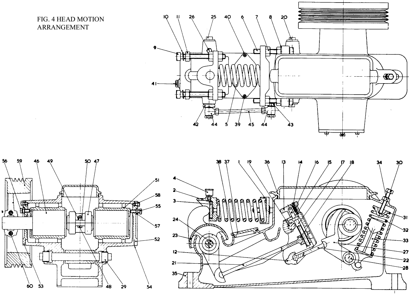
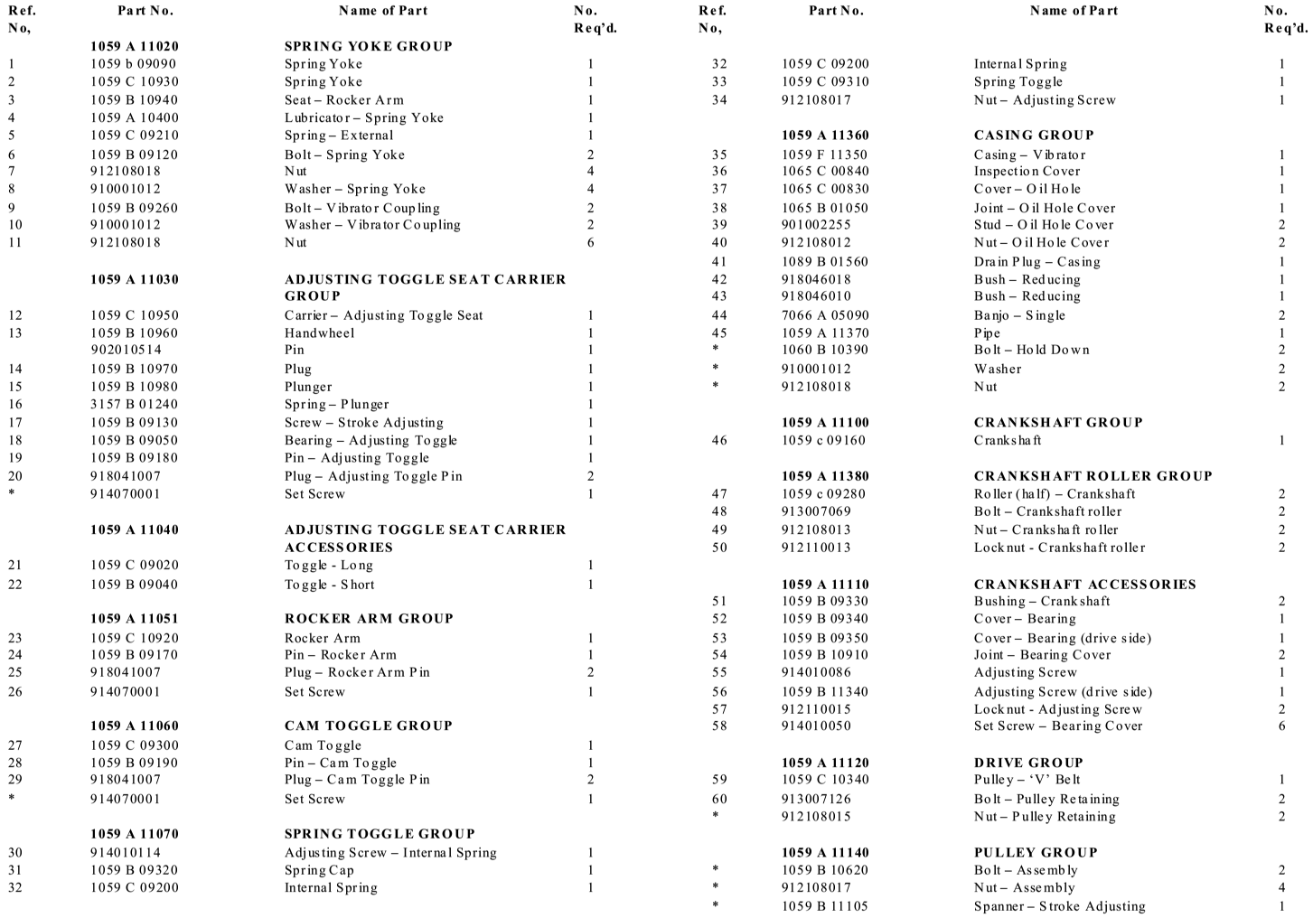
“Tapping noises” with each stroke may occur after some initial wear/bedding in of internal components. The internal spring holds all internal parts in position, and provided oil level has been maintained and all other internal gearbox components are in good condition, minor adjustment (half turn at a time ) of the internal spring adjusting screw (item 30) should return the unit to silent operation. Provided regular oil changes are maintained, and dirt/sand is prevented from entering the gearbox, internal parts will provide long service life.
Initial signs of wear are usually at the rocker arm seat/rocker arm pivot point (parts 3 & 23).
However again, provided regular oil cup checks are made, the life of components here can be one to two years minimum.
Monthly
Lubricate tilt hand-wheel bearings and shaft (grease points fitted)
Check Location bolts for gearbox, and drive motor are secure
Check High tensile drive to deck connection bolts are secure (two off)
Six monthly (in addition to monthly checks)
Check security of ALL foundation holding bolts
Check security of all fixing bolts for wash water/feed box brackets
Check security and condition of deck carrier straps (42 off) supporting the deck
Clean down (soft brush) any build up of deposits on the deck surface, and check riffle condition.
Clean/flush the wash water bar holes to allow even wash water distribution across the deck
Holman Head Motion
Lubrication
Recommended Oils
Shell Helix automotive 20W/50 engine oil
The vibrator casing and the oil cup on the spring yoke must be filled with oil. The oils listed above are recommended for use, but other brands, which have an equivalent specification, may be used. Good quality automotive 20W/50 engine oil is suitable.
Filling Instructions and Oil Change
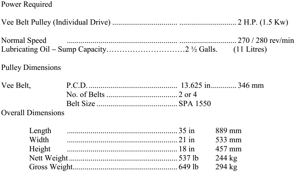
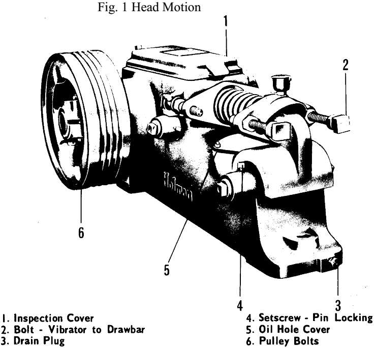
The internal parts of the vibrator are splash lubricated from a sump in the casing. 2½ gallons (~11 litres) of oil are required to fill the casing to normal working level. Weekly checks should be made of oil level (SEE FIG. 2, PAGE 13), and topped up if necessary to ensure adequate splash lubrication. Providing recommended oil is used, the oil in the casing should be changed approximately every 2,000 hours. Removing the drain plug located in a central position in the front of the casing, Fig. 1, can drain the oil.
The amount of oil in the spring yoke cup should be checked regularly.
Specification
Dismantling Instructions
The Head Motion can be dismantled without being removed from the foundations. It is important, after completing maintenance work, to ensure that the head motion is free by rotating it by hand for a few revolutions. When it has been dismantled, every part should be thoroughly cleaned and examined for wear and any parts found to be faulty must be replaced.
To Remove the Spring Yoke and External Spring
- With the vibrator at the forward end of the stroke, insert a suitable timber wedge (Z) Fig. 2 between the rocker arm (19) and the vibrator casing.
- Adjust the rear spring yoke screws until it is possible to insert a timber wedge (15 mm) in thick between the casing and the rear spring yoke (3).
- Remove the spring yoke bolts and insert minimum 12 mm diameter threaded bar, 300mm long between the front and rear spring yokes. Fit flat washers and nuts to each end, and tighten nuts evenly to compress the spring until the timber wedge is free. Lift the complete spring yoke assembly clear of the casing.
To Remove the Rocker Arm and Adjusting Toggle Seat Carrier
Having removed the spring yoke assembly, proceed as follows:-
- Remove the drain plug (3) Fig. 1 and drain the oil.
- Remove the oil hole cover.
- Release the timber wedge from under the rocker arm, so that the adjusting toggle seat carrier (17) will move forward and the short and long toggles (16 & 18) can be removed, Fig. 2.
- Release the retaining screws from the pivoting pins of the adjusting toggle seat carrier (17), the cam toggle (15) and the rocker arm (19). Remove the retaining plugs, withdraw the pivoting pins and parts in the following order:-
The rocker Arm
The adjusting seat carrier assembly
The cam toggle
To Remove the Crankshaft
- Dismantle the assemblies as in the previous two paragraphs.
- Remove the pulley and the two bearing end covers.
- Detach the roller (8) from the crankshaft (7).
Using a brass drift, tap the crankshaft bushing on the drive side from inside the casing and withdraw it form its seat.
In carrying out this operation, it should be remembered that the crankshaft bushing bears on two diameters and, therefore, the crankshaft must be held in a central position until the bushing is free. - Remove the crankshaft and tap out the remaining bushing.
Assembly Instructions
The head motion should be assembled in the following order
To replace the Crankshaft and Cam Toggle
- Insert the crankshaft bushing in the housing opposite to the drive end. Insert the crankshaft (7).
- Offer the other crankshaft bushing into the drive end housing, support the crankshaft and tap the bushing into its correct place.
- Rotate the crankshaft until the roller journal is in the top dead centre (T.D.C.) position.
- Position the two halves of the roller (8) on the journal and secure in place with connecting bolts, nuts and locking nuts.
- Place a gasket joint over the crankshaft end covers, position the covers and secure them in place with set screws.
- Lower the cam toggle (15) into the casing; insert the toggle pivoting pin (14), the locking screw and the two pin retaining plugs.
- Insert the two bushing adjusting screws in the end covers, and adjust the screws until the roller (8) is centralised to the cam toggle (15). This should give 0.125mm end clearance each side between the flange of the crankshaft and the bushings.
To replace the Spring Toggle
- Turn the crankshaft until the roller is in a position 90 degrees to T.D.C. and the cam toggle is in its lowest position at point ‘Y’ Fig. 2. Position the spring toggle (13) in the cam toggle, insert the spring (12) and cap (11). Compress the spring by applying pressure to the cap, slide the complete assembly into position as shown Fig. 2 and insert the adjusting screw (10).
- This screw must be adjusted until the cam toggle will just return the roller to it’s natural position. Care must be taken when adjusting the screw as excess spring pressure will cause unnecessary wear to the roller.
To replace the Rocker Arm, Adjusting Seat Carrier and Toggles
- Pre-assemble the complete adjusting seat carrier, comprising the carrier, adjusting toggle bearing, stroke adjusting screw and hand wheel assembly.
- Place the two toggles in the casing, with the short toggle below the carrier and the long toggle below the oil hole.
- Insert the complete adjusting seat carrier, position and secure its pivoting pin. Replace the plugs either side of the pin.
- With the left hand, pick up the short toggle and engage and hold it in its seat in the cam toggle. With the right hand through the oil hole, ease the base of the carrier forward and engage the front of the toggle in its seat in the base of the carrier. Apply light rearward pressure with the right hand to keep the toggle in position.
- With the left hand, insert a piece of timber, 50 x 25 x 295 mm. long between the stroke adjusting hand wheel and the top rear edge of the inspection cover opening. Thus wedging the short toggle in place.
- With the right hand through the oil hole, pick up the long toggle and insert it in position in the adjusting toggle bearing, resting the other end on the bottom of the casing.
- Lift the rocker arm into place, locate and lock its pivoting pin in position.
- With the right hand, push the top of the rocker arm rearward, and with the left hand, insert the long toggle into its seat in the rocker arm, ensuring the rear end of the toggle is correctly located in the adjusting toggle bearing. A timber wedge can now be placed in position Z, which will keep the whole assembly in place.
- Replace the plugs either side of the rocker arm pin.
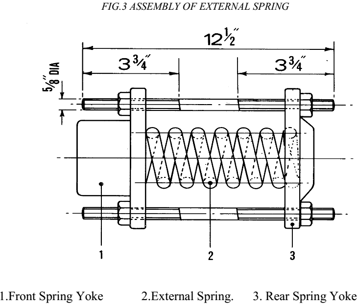
- Using the two long screws, assemble the external spring (2) Fig. 3 and spring yokes (1 & 3). The nuts should be screwed on until the spring is sufficiently compressed as to allow the complete assembly to be dropped in position. It should engage in the rocker arm end first and a wooden wedge (4) (15 mm) thick must be inserted between the casing and spring yoke, Fig. 2.
- Remove the long screws from the spring yoke (3) end, extract the screws, insert the spring yoke bolts, nuts and washers and remove the wooden wedge.
- The spring yoke bolts must now be adjusted until the distance between the two yokes is approximately (170 mm) on both the right and left hand side of the spring.
- Finally remove the timber wedge from under the rocker arm, replace the oil drain plug, refill with ~11 litres (to oil level plug) of the recommended oil and replace all the covers.
