rock cone crusher zoom

Hover

rock cone crusher zoom

Hover

rock cone crusher zoom

Hover

rock crusher cone zoom

Hover

cone rock crusher zoom

Hover

cone crusher zoom

Hover

rock cone crusher zoom

Hover

rock cone crusher zoom

Hover

rock cone crusher zoom

Hover

rock cone crusher zoom

Hover

rock cone crusher zoom

Hover

rock cone crusher
rock cone crusher
rock cone crusher
rock crusher cone
cone rock crusher
cone crusher
rock cone crusher
rock cone crusher
rock cone crusher
rock cone crusher
rock cone crusher
Full Screen

Cone Crusher (36″) 20 to 50 TPH

US$100,000

Our small cone crushers are suitable for crushing various ores and rocks with compressive strength no more than 300 MPa. PYB is suitable for intermediate crushing, PYZ and PYD are for fine crushing.china manufacturer

The cone crusher consists of a mainframe, transmission device, eccentric locking collar, bowl bearing, crushing cone, adjusting device, adjusting sleeve, springs, feeding part, flexible coupling, hydraulic station, dilute petrol station, electric control, etc.

During the operation, the motor drives the eccentric sleeve to rotate through the horizontal axle and bevel gears. The center axle of the crushing cone swings with the force of the eccentric shaft sleeve so that the crushing surface is close to the mortar from time to time. In this way, the materials will be crushed through continuous pressing and bending.

test
Category:

Description

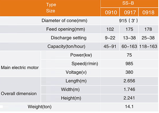
Cone Rock Crusher Models

rock crusher cone.jpg

Cone Crusher Parts

cone rock crusher parts.jpg

Installation and trail-run

  1. This instruction manual only includes some special installation instructions for the machine. The rest can refer to the instructions of general machines.
  2. The lifting equipment

In the crusher installation room, there should be lifting equipment that will be used for installation and doing maintenance. The lifting device can be chosen from the following table according to its lifting ability.

rock cone crusher

cone crusher

cone crusher in shipping container
cone crusher in a shipping container

Cone Crusher Installation instructions

  1. Check the number of the parts before installation. Check and make sure there is no damage to the surface of the parts and the thread during transportation and clean the protect painting and the dust or dirty materials on the parts.
  2. When installation, smear some dry oil on the fixed surface and smear some thin oil on the movable surface.

Cone Crusher Foundation

  1. The crusher should be installed on a concrete base. The depth of the concrete is determined by the local soil conditions.
  2. To prevent the rocks from piling, there should be enough space under the base for transmission equipment.
  3. To protect the base, there should be a protection board put on the base. Clients prepare it themselves.
  4. We provide foundation diagrams only for reference, not for foundation construction.
  5. The position of the lubrication system and the electric controlling system can be changed according to a different environment, but the sequence cannot be changed.

Cone Crusher Frame Installation

  1. Strictly vertical and horizontal requirements must be ensured when installing the frame. Use the gradient and suspender to check the central line of the bottom base on the ring surface. (see diagram 3)
    Cone Crusher Installation of Frame
  2. After adjusting the bottom base with the adjustment wedge, fasten the ground bolt and start the second grouting.
  3. When the second grouting is fixed, withdraw the wedge from the bottom of the crusher and fill the gap with concrete. Then, check under the condition of frame installation (1).
  4. Keep the bottom base vertical and horizontal. Make sure the machine operates properly, otherwise, the copper sleeve will be unevenly touched, the eccentric bushing will be worn and the sealing device will be out of work.

The installation of the transmission shaft.

  1. Put an adjusting shim between the bulges of the frame and transmission shaft when installing the transmission shaft.
  2. After installing the transmission shaft, use a template to check all the sizes concerned with the transmission gears.
  3. The moving range of the transmission gear at shaft direction should be kept between 0.4-0.6 mm.
  4. When dismantling the transmission shaft, use the square head bolt on the flange to prop it up. The square bolt should not be fastened without dismantling the transmission device.

Cone Crusher Installation Drawing

Installation of hollow eccentric shaft

  1. Before installation, put the mat on the bottom cover. Then, use a sling to put the cover under the frame. After that, put the upper round plate and a lower round plate on the bottom cover in sequence and make sure the heave place on the lower plate and the concave place in the bottom cover is locked as shown in diagram 5.
    Cone Crusher Installation Drawing of Thrust Bearing
  2. When installing the hollow eccentric shaft, a round-end bolt can be used to put the eccentric shaft into the central hole in the frame. Be sure the gears are not stricken when installing as shown in diagram 6.
  3. After installation of the hollow eccentric shaft, the out surface of the big and small gear must be at the same level and check the gap between the gears. The gap is about 2.1-2.58mm, and the tooth top gap is ≥ 50%, and the length is ≥ 50% as shown in diagram 7.

Cone Crusher Install Tool

Cone Crusher Align

The installation of bowl-shaped bearing

  1. Preparation
    a. Clean out the sundries in the oil groove and oil hole.
    b. Check scraper seal and oil deflector.
    c. check the surface of all parts, if damaged, repair it at once.
  2. The frame of bowl-shaped bearing and frame of the whole machine should closely cooperate, and check the closeness of horizontal interface with a filler gauge as shown in Diagram 8.
    Cone Crusher Filler Gauge
  3. After the installation of the bowl-shaped bearing, cover the bowl-shaped tile with the cover plate immediately and take out the cover plate when installing the crushing cone.
  4. Pay attention to protect scraper seal and oil deflector, avoid damage during installation.

The installation of crushing cone

  1. Before installing, set a high and fixed wooden rack nearby to prepare for the installation.
  2. Remove the protective oil layer on the main shaft and the spherical surface; dry the lubrication oil hole and oil channel with the wind.
  3. Spread a layer of lubrication grease on the prick of the main shaft and a layer of machinery oil on the spherical surface.
  4. Install the crushing cone into the eccentric shaft slightly to make spherical surface contact with the bowl-shaped shaft, as shown in Diagram 9. Take care and not damage the ring circle and protective circle.

Cone Crusher Bowl Shaped Shaft

The installation of the lubrication system

  1. The lubrication system can be installed by means of the diagram, or according to the local actual situations. The assembly diagram decided by the clients and the parts needed is prepared by the clients themselves.
  2. Make sure the lube circuits smoothly.
  3. The lubrication system should be fixed first before the installation of crushing cones in order to test the lubrication system. It will be more convenient to dismantle or repair the lubrication system if there is any faults.

Trial-run without load

After the above-mentioned steps finished, a trial-run without load experiment needs to be done to check whether the installation is qualified, so as to repair the inappropriate parts in time.

  1. Check the firmness of main junctions before starting the machine.
  2. The machine should be started manually to ensure the empty eccentric shaft keeps rotating for more than 2 to 3 rounds smoothly. There should be flexible operation and without lock before starting the machine.
  3. Start the oil pump ahead of time to lubricate the parts that should be lubricated till the oil goes back to the oil station, then start the equipment.
  4. The trial run without load should last continuously for more than 2 hours.
  5. The trial-run should meet demands as follows:
    A. The rotating speed of the crushing cone around its central line should be less than 15 rounds/minutes.
    B. There should be no periodical noises in the cone gears.
    C. The lubrication system should meet demands as follows:
    a. Pressure for pumping oil should be within 0.08-0.15 MPa.
    b. Temperature of the returning oil should not be higher than 50 °C.
    D. When dismantling the abrasive parts in the cone crusher after the trial run, there should be no burn or abrasion.
  6. If the rotating speed of the crushing cone is abnormal, stop it and check immediately, repair it if there is something wrong. Check the oil feeding amount and then do the trial run again.
  7. If there is periodical noise in the gears, check the correctness of cone gear installation and the gap between cone gears.

Installation of the adjustment device, adjusting sleeve and springs (see diagram 11)

Cone Crusher Installation of Adjustment Device

  1. Clean the supporting sleeve and the adjusting ring. Smear mixer of dry and watery oil on the toothed whorl. Install locking oil tank on the supporting sleeve. Connect locking oil tank with the hydraulic station.
  2. Install the supporting sleeve onto the mainframe.
  3. Put the adjustment ring into the supporting sleeve.
  4. Put the lock-nut on the supporting sleeve, and knock four pins into the four pinholes.
  5. Install the hopper device and hopper.
  6. Install dust cover, and pay attention to imbed the four key chucks of the adjusting ring into the card slot of the dust cover.
  7. Adjust the operational height of the spring according to the specifications of the drawing.
  8. Install the push cylinder and the energy accumulator. First, the installation of the push cylinder, the two interfaces of M and N in the push cylinder are connected on M and N in the hydraulic station as shown in diagram 12. Second, the energy accumulator is installed on the pillar of the feeding device by clip and the interface is connected to the oil line of the locking cylinder by means of hose and cross pipes as shown in diagram 13.

Cone Crusher Installation of Push Cylinder

Cone Crusher Installation of Energy Accumulator

Installation of feeding device

Cone Crusher Installation of Feeding Device

  1. Incorrect installation will lead to the following troubles.
    a. Capacity is lowered.
    b. The size of the final product is uneven, big size covers a large percentage.
    c. The readability of the wear parts is not even or they wear too quickly.
  2. The height between feed opening and distributor is very important to the crusher. If it is too high, the raw materials cannot easily enter the crushing chamber. Therefore, the height should be based on the instructions.
  3. An accurate steel plate is used to protect the feeding box from damage and protect the materials from being stuck in the feeding box. When installation, keep the arc steel plate in good shape and pay attention to the space between the arc steel plate and the edge of the feed opening to protect materials from being stuck as shown in diagram 15.

Cone Crusher Feeding Device

The installation of hydraulic station and adjustment experiment

  1. The hydraulic station is placed on the base to conveniently operate and connects all the parts of pipes and hose. It can be laid out according to the actual situation.
  2. The three interfaces, that is, M, N, P of the hydraulic station are connected respectively with M, N, P in the push cylinder and locking cylinder.
  3. After the above steps, the bulge test is made, with the test pressure 140kgf/cm.
  4. Locking test
    A. Input 75-80kgf/cm² nitrogen into the accumulator before bulging into the locking cylinder.
    B. Bulge into the locking cylinder after the push cylinder releases pressure.
    C. The remaining gases in the locking cylinder and the pipe in the test can be discharged by removing the pipe or plug in the bottom of the accumulator.
  5. The adjustment test, that is, uses the push cylinder as the test of adjusting the throat after releasing the pressure of the locking cylinder.
  6. Make sure the parts of the hydraulic station are good and the operation is flexible as shown in diagram 16.

Cone Crusher Hydraulic Station

Trial-run with load

  1. If the no-load test is ok, the load test can be taken.
  2. The load test should last 48 hours(shortstop for checking is allowed).
  3. At the beginning of the load test, put a small quantity of rocks into the crusher, then, gradually add the quantity to be a full load.
  4. The load test should reach the following requirement:
    A. There is no acute vibration and no big noise.
    B. Both the feeding and discharging are in good condition. The capacity is similar to the stipulated capacity.
    C. The hydraulic station operates well.
    D. The lubrication system should meet the following requirement:
    a. The pressure of the oil should be within 0.8-1.5kgf/cm².
    b. Temperature of returned oil should be lower than 50 °C.
    E. There is no damage to the wearing parts.
    F. The electric system is in good condition.

Maintenance

Notes

  1. The materials must be in the middle of the distributor. It is not allowed to put the materials into the crushing chamber directly, because it will make the crusher overloaded and the liner plate will be abraded unevenly as shown in diagram 14.
    Correct feeding conditions:
    a. The materials are distributed equally to the crushing chamber.
    b. The number of materials should not higher than the concave level as shown in diagram 15.
  2. The max feeding size should not equal to the feed opening, (the max feeding size ≤85% of the feed opening) otherwise, it will lead to:
    a. The capacity is low.
    b. Some parts will be damaged.
  3. Crusher is not allowed to start with load condition in case of an accident.
  4. When stop the crusher, stop the feeder first. After the materials are all discharged out, stop the crusher.
  5. The locking system and hydraulic station should be checked often to avoid problems.

The capacity of the crusher

Capacity is subject to feeding method, material size, size of the final product, material nature, temperature, etc. the range is wide. The capacity provided by the manufacturer is calculated under certain conditions.

Change of Concave

There are u-shaped bolts on the adjusting ring for fixing the concave, and fill zinc alloy into them. When installing or changing the concave, after 6-8 hours’ operation, check the fastening conditions and screw the U-shaped bolts again.

Change of the crusher inner wall

The cone crusher inner wall is fixed to the cone crusher body through a cone end. There is zinc alloy between them. When installing or changing the inner wall, after 6-8 hours’ operation, check the fastening conditions. If there is loose, fasten it.

Bowl-shaped bearing and sealing device

When installing the bowl-shaped bearing, make sure the oil seal is not damaged by the steel wire (can use hardwood to support between the steel wire).

When assembly, scrape the spherical surface to ensure the crushing cone and bowl bearing touch at the excircle, and the space between the crushing cone and the spherical surface is kept within 0.35mm.

The bowl-shaped tile is fixed to the bowl-shaped bearing support through lock pins to prevent the tile rotate in a circle. The bowl-shaped bearing support and the frame are fixed together by a lock. If there is space between the support and the frame, deal with it immediately.

The cylinder liner

The cylinder liner and the frame is the third transient assembly. To avoid the liner rotating, the upper part of the liner is filled with zinc alloy. When changing the new liner, make sure it is according to the practical size because after a long time’s operation and assembly, some changes may happen to the crusher. If the space is too large, the liner will be broken.

Conic liner

The cone sleeve and the eccentric shaft should wring each other. Fill in some zinc alloy to stop the cover from rotating. Space should be full of zinc alloy. The sleeve may change its shape due to the hot zinc alloy, so check the size of D1d1, D2d2, and B of a new cover. If it is incorrect, correct it. When making spare parts, make sure it is fit for the practical side of the inner diameter of the eccentric shell as shown in diagram 17.

Cone Crusher Eccentric Shell

Springs

  1. The functions of springs are: when some unbroken materials enter the crusher, they will prevent the crusher from damaging. Therefore, the pressure of the springs and the crusher is corresponding to each other. If the crusher is in good condition, the spring is stable; only when unbroken materials enter the machine will the springs be pressed.
  2. If the upper part of the crusher vibrates, clients are required to check the machine carefully and solve the problem. If pressing the springs incorrectly, some parts may be damaged, because pressing the spring will increase the pressure of the crusher.
    The reason why the upper parts of the crusher vibrate are:
    A. Feeding unevenly or overfeeding.
    B. There are many small lump materials in the raw materials or the humidity is too high.
    C. The discharge opening is too small.

The outer rotation parts of the crusher should be protected with the cover which is prepared by clients.

Lubrication

Lubrication system

Cone Crusher Lubrication System

Since the friction surface receives much pressure, and the speed is so high, lubrication is very important to the crusher. The crusher is centrally lubricated with middle circulation.

Two routes for the oil to enter the machine (diagram 18):

  1. One route enters into the disc of lubricating thrust bearing and bushing through the oil hole at the bottom of the crusher, then to the hollow eccentric shaft surface, bowl-shaped bearing and the big and small gears, and back to the oil box from the oil hole under the small gear.
  2. The other route is through the hole in the transmission shaft support, then to the transmission bearing. The return route is a spill hole at the bottom of the small bevel gear and another spill hole in the dust-proof cover.

To make sure that the crusher is fully lubricated when operating, the lubrication system and main machine of the crusher, feeder, and conveyor adopts electric junctions. Before starting the main machine, start oil pump first, or the main motor is not able to be started successfully; when the oil pump stops or oil pressure falls below 0.05 MPa, or oil temperature upswings over 60 °C, warning messages can be sent out and the running feeder motor stops so that no damage will be made on main parts of the machine.

Choice of lubrication oil

Choose machinery oil No. 32 or No. 46 in winter, Choose machinery oil No. 100 in summer, for normal temperature, can choose machinery oil No. 68.

The comparison table of new and old standards of lubrication oil is shown in the following table for reference:

Cone Crusher Comparison Table

The hydraulic pressure of the cooler is generally lower than oil about 1.25-0.5kgf/cm². The temperature of the water is 20-25°C, and the water must be clean.

The oil pressure of the crusher must reach 0.8-1.5kgf/cm², that is, after the lubrication oil reaches the lubrication point, the main motor can be started.

When the oil pressure is lower than 0.8kgf/cm², the electrical control system will give out the signal and stop feeding, therefore, the problem must be dealt with timely.

The temperature of lubrication oil may rise due to long-time work, but it cannot be higher than 50 °C, or the crusher should be stopped quickly to solve the problem.

After the crusher stops work several hours in winter, measures must be taken to prevent the oil frozen in the fuel tank and oil tube. The best way is to spin without load at regular intervals. Use the resistance heating in the fuel tank when necessary.

For the new crusher, the lubrication oil should be changed one time every 1 to 1.5 months at the first 3-4 months, and afterward, it will be changed one time every 3-4 months and replenish the lubrication oil at regular intervals.

Keep the filter clean, if the oil feeding is reduced, it may be due to the clogging of the oil screen, so the machine must be stopped to be repaired in time.

The examination, cleaning, and repair of the oil line is no less than one time a year.

When cleaning the pipe of the lubrication system, choose the place of impurity and dirties sediment to check, such as in the crook of the pipe, according to the checked result, determine which part to clean, the whole pipe or the part.

After changing the new oil, the machine operates for one to five days and nights and the filter system needs to be cleaned, and repair in every year’s maintenance.

The examination of the oil pump is no less than one time every year, the pressure gauge and other parts are checked half a year.

When the lubrication system stops, the oil level in the oil holder should reach the upper limit. But, when the lubrication system operates, the oil level should not be below the lower limit.

Operation Regulations

  1. Open oil rarefying station before starting the main machine, the main machine can be started only after the lubrication system works normally. Open the feeder when the crusher without load runs normally.
  2. Stop feeding before stopping the crusher. Make sure that all raw materials in the crushing cavity are all discharged after being crushed and then stop the machine. Stop oil pump of oil rarefying station finally.
  3. Before starting the oil pump of the oil rarefying station, open the related oil and water valves and switch of pressure gauge. Regulate the pressure coordinate to make the oil feeding pressure within the range of 0.04-0.1 MPa. Oil temperature should be between 30 °C- 40 °C. If the oil temperature is too low, open the resistance heater to heat the oil.
  4. See the functions of every electrical switch at the part of the circuit instruction in the shown diagram. Put them in the right positions before starting the machine.

Trouble and troubleshooting

Cone Crusher Trouble and Troubleshooting
Cone Crusher Trouble and Troubleshooting 2
Cone Crusher Trouble and Troubleshooting 3
Cone Crusher Trouble and Troubleshooting 4

I Need Assistance