DESCRIPTION


Drum-Type Magnetic Separators
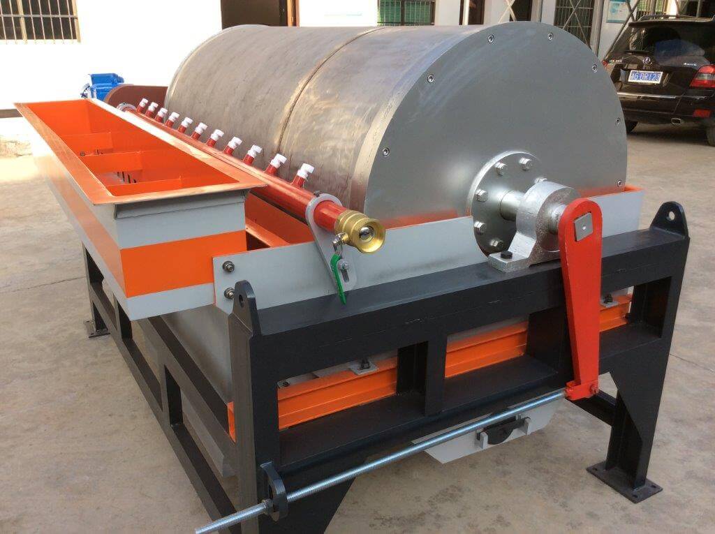
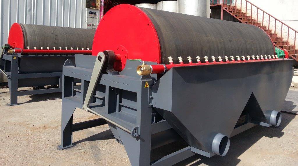
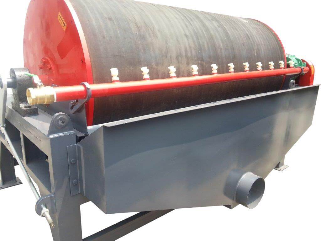
Permanent magnetic drum separators combine the attributes of a high-strength permanent magnetic field and a self-cleaning feature. These separators are effective in treating process streams containing a high percentage of magnetics and can produce a “clean” magnetic or non-magnetic product. The magnetic drum separator consists of a stationary, shaft-mounted magnetic circuit completely enclosed by a rotating drum. The magnetic circuit is typically comprised of several magnetic poles that span an arc of 120 degrees. When material is introduced to the revolving drum shell (concurrent at the 12 o’clock position), the non-magnetic material discharges in a natural trajectory. The magnetic material is attracted to the drum shell by the magnetic circuit and is rotated out of the non-magnetic particle stream. The magnetic material discharges from the drum shell when it is rotated out of the magnetic field.
Permanent magnetic drum separators have undergone significant technological advancements in recent years. The magnetic circuit may consist of one of several designs depending on the application. Circuit design variations include:
- Standard Axial
- High-Gradient Axial
- Interpole
- Salient Pole
- Radial Pole
- Criss-Cross
The standard magnetic drum configuration consists of series of axial poles configured with an alternating polarity. This type of drum is simple in design and can be effective for low-intensity applications such as the recovery of ferrous metals and magnetite. This configuration typically does not provide a sufficient field strength or gradient for the recovery of paramagnetic minerals at high capacities. A typical axial circuit is shown in Figure 3.

The high-gradient element, as the name implies, is designed to produce a very high field gradient and subsequently a high attractive force. Several identical agitating magnetic poles comprise the element. The poles are placed together minimizing the intervening air gap to produce the high surface gradient. Due to the high gradient, the attractive force is strongest closer to the drum making it most effective when utilized with a relatively low material burden depth on the drum surface and, thus, a lower unit capacity. A high-gradient magnetic circuit is shown in Figure 4.

The interpole-style element utilizes a true “bucking” magnetic pole or “interpole” between each main pole. The magnetic field of the bucking element is configured to oppose both of the adjacent main poles resulting in a greater projection of the magnetic field. As a result, the interpole circuit allows for a relatively high material burden depth on the drum surface and thus higher unit capacity or improved separation efficiency. An interpole magnetic circuit configuration is shown in Figure 5.

A second interpole configuration consists of steel pole pieces placed between the magnetic poles. This is commonly termed a “salient-pole” element. The steel interpoles concentrate the magnetic flux providing a very high magnetic gradient at the drum surface. The magnetic field configuration is similar to the “high- gradient” type element but with an intensified surface gradient. This configuration offers the strongest field projection of any of the previously described circuits. The salient-pole circuit design is shown in Figure 6.

The magnetic elements described above are axial elements. The magnetic poles run across the width of the drum and are of alternating polarity. Magnetic elements are typically assembled with a minimum of five magnetic poles that span an arc of 110 degrees. (For all practical purposes, an arc of only 80 degrees is required to impart a separation. Non-magnetic particles usually leave the drum surface with a natural trajectory at a point of 60 to 70 degrees from “top dead center” dependent on the drum speed, particle size, and specific gravity.) The poles have alternating polarity to provide agitation to the magnetic components as they are transferred out of the stream of the non-magnetics. A magnetic particle will tend to rotate 180 degrees as it moves across each pole. This agitation is functional in releasing physically entrapped non-magnetics from the bed of magnetics. Agitating magnetic drums are most effective in collecting fine particles or where the feed contains a high magnetics content.
DENSE-MEDIUM CIRCUITS BY MAGNETIC SEPARATORS
Dense-medium circuits have been installed in many mineral treatment plants since its original development about thirty years ago. In the intervening period the process has been thoroughly evaluated and many innovations have been introduced. The Heavy Density Cyclone is one of the newer systems which has extended the operating range of this process to 65 mesh size.
The magnetic separator performs three basic functions:
- Medium recovery
- Medium cleaning
- Liquid rejection
Medium recovery is obviously important since any loss is a direct cost against production. In coarse coal dense-medium plants a loss of 1 pound of magnetite per ton is usually acceptable but reduction to ½ pound per ton as has been obtained in some plants.
Efficient cleaning maintains fluidity in the bath and increases sharpness of the coal-waste separation. Most dense-medium systems will tolerate some non-magnetic dilution of the bath but the magnetic separator must be capable of keeping this within workable limits, particularly on difficult coals. In some plants a partial bleed of the operating dense-medium bath is maintained through the magnetic separator to keep it clean.
Operating gravities of dense-medium coal plants are usually low enough so that a straight magnetite bath can be used. The return of a magnetic separator concentrate having 50% or more solids will maintain gravity without need for a thickening device. The use of a drum wiper has permitted the return of a 70% solids concentrate back to the separatory vessel. Operation at a high solids concentrate discharge is recommended since medium cleaning is improved. The colloidal slimes carried over with water are more completely rejected at high solids discharge.
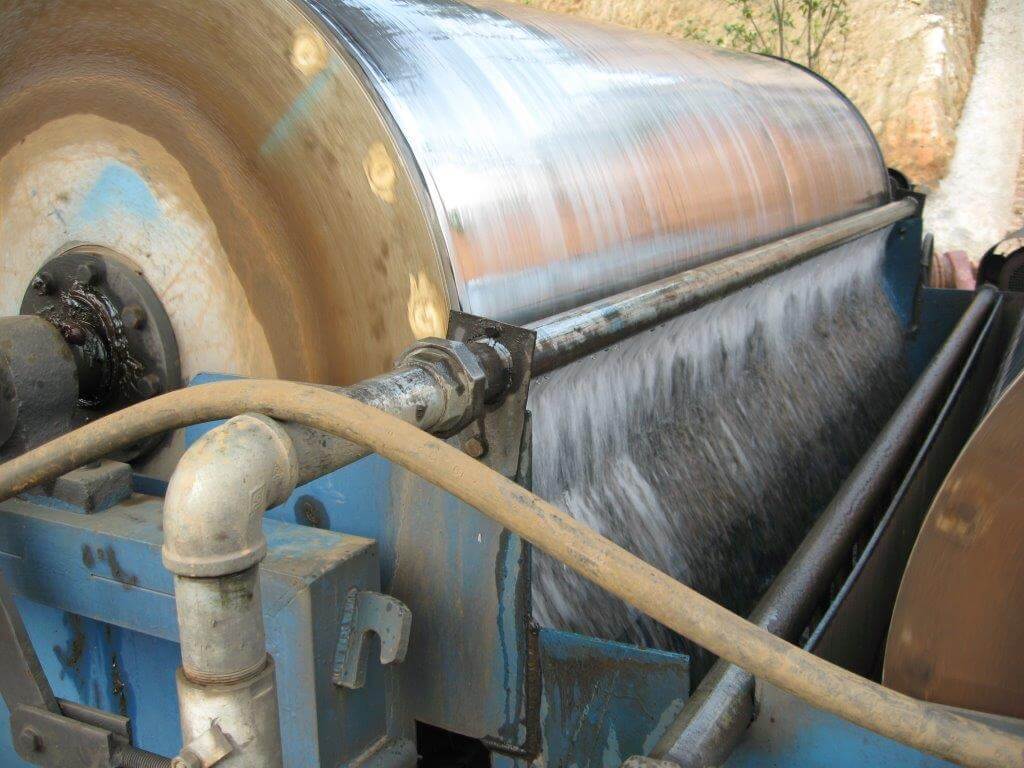
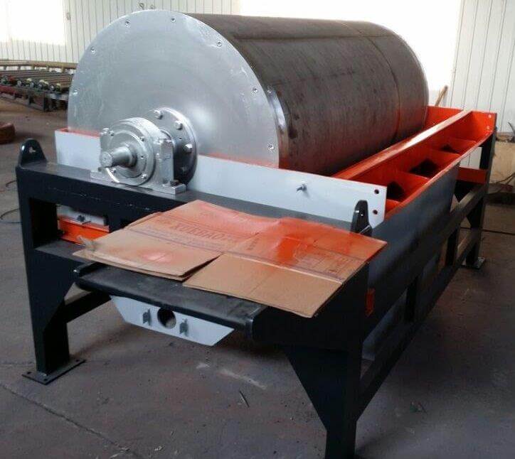
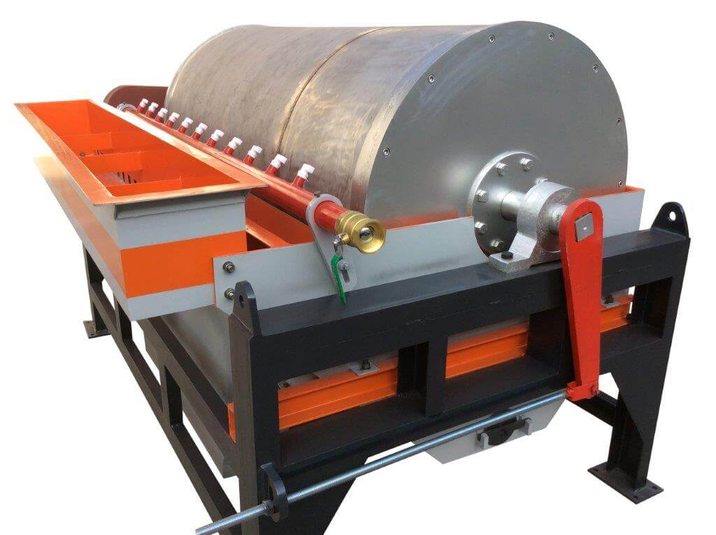
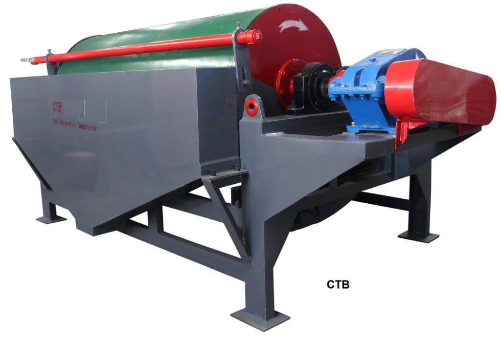
Several types of magnetic separators have been used in magnetic medium recovery. The first magnetic drum separators were electro magnetic types but the development of efficient wet permanent drum separators has resulted in nearly universal acceptance of permanent drums in new plants.
The basic construction of each drum is the same. It consists of a stationary magnet assembly held in a fixed operating position by clamp bearings mounted on the separator support frame. An outer rotating cylinder driven through a sprocket bolted to one of the drum heads carries the magnetic material to the magnetic discharge point.
Five factors normally influence the specific selection of a magnetic drum separator in dense-medium plants;
- Volume of rinse water to be handled
- Percentage of solids in the rinse slurry
- Percentage of magnetics in the feed solids in the slurry
- Required magnetic efficiency
- Purity and solids content required in magnetic concentrate
Normally, extreme cleanliness of the magnetic concentrate is not of prime importance in dense-medium plants but this can be a factor in some coals that separate with difficulty. The concurrent tank, reduced separator loading and in some instances dilution of the feed pulp will improve magnetic cleaning. Recleaning of a primary concentrate would improve cleaning but has not been used in commercial plants.