Absorption is caused when incoming X-rays get absorbed by the elements in the sample and do not get the chance to diffract. This results in lower diffraction peak intensity and therefore, a lower peak-to-noise ratio.
Secondary fluorescence occurs when incoming X-rays excite core electrons from specific elements present in the sample causing increased background and therefore, a lower peak- to-noise ratio. The Olympus Smart Sense filter compensates for this occurrence by filtering out some amount of the counts that have a different energy than the X-ray source although it simultaneously decreases the overall X-ray signal.
OPTIMIZING PEAK SHIFT
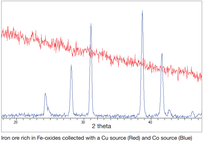
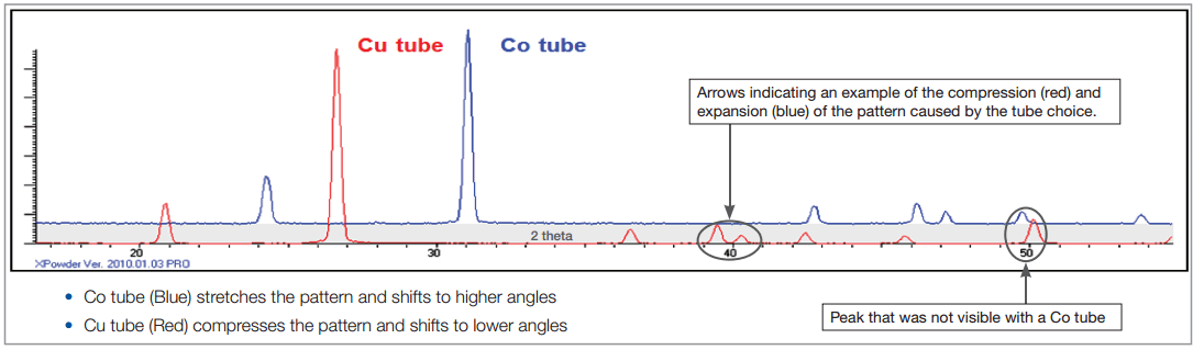
The XRD fingerprint is specific to each compound. Some compounds have critical identifying peaks that show up at very low angles or very high angles. The choice of Cu or Co tube has two effects on the peak placement within our detector’s visible range of 5 – 55° 20: shift in the 20 range and compression/expansion of the pattern. The right tube choice will result in the optimum shift to see the peaks of interest for a particular substance.
A Cu tube compresses the XRD pattern and shifts to low angles as compared to Co. As a result, a wider range of diffraction peaks become visible and more XRD information for compound identification can be collected but there can be a tradeoff in resolution caused by the compression of the pattern, which can result in peak overlap.
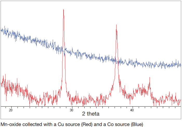
A Co tube shifts the XRD pattern towards high angles, increasing the visibility of low angle peaks. The diffraction peak information collected at low angles is especially important for clay minerals typically showing an intense peak at low angle, but there can be a tradeoff in missing diffraction peaks at high angles.
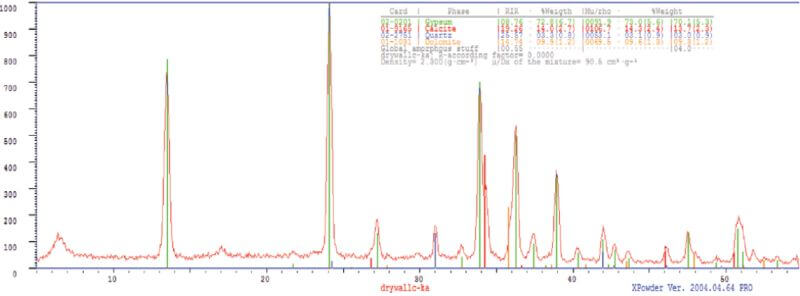
Quartz Sample Measured With a Co and With a Cu Tube
For applications with sample matrices affected by the X-ray tube, the choice between a Cu and Co is a matter of balancing the various effects such as the ones described in this document. The Olympus team of application scientists is available to assist with XRD instrument selection and configuration for your specific application needs to achieve the best possible results.
Easy Sample Preparation
BTX radically simplifies sample collection and preparation for your X-ray diffraction experiments. Typically, a sample must be finely ground and pressed into a pellet in order to ensure a sufficiently random orientation of the crystals.
BTX’s patented sample vibration chamber eliminates that issue. Requiring a mere 15 mg sample, the vibration chamber’s convection process presents the instrument optics with multifarious orientations of the crystalline structure. This results in a superb X-ray diffraction pattern, virtually free of problematic preferred-orientation effects encountered when using classic preparation methods.
Due to its unique powder handling system, nonmechanical goniometers, and lack of complicated moving parts, BTX is able to provide full laboratory-grade powder XRD performance at a fraction of the price.
XPOWDER SOFTWARE
BTX is shipped with the necessary software (XPowder) for processing the resulting X-ray diffraction data. This includes the AMSCD mineral database. Should the user wish, XPowder provides the ability to use the ICDD Powder Diffraction Files (PDF).
For quantitative analysis, XPowder comes complete with reference intensity ratio (RIR) quantitative analysis methods as well as full-pattern analysis tools.
Furthermore, BTX provides XRD pattern data in a variety of file formats, making XRD pattern interpretation in third-party programs easily accessible.
CONNECTIVITY
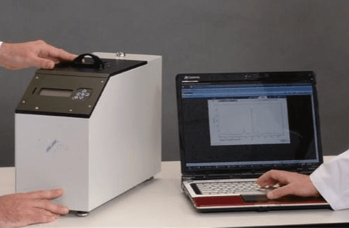
BTX operates off software embedded in the unit itself. The user accesses the operating system through an Ethernet or a wireless connection (802.11b/g). This remote operation method allows for a wide degree of flexibility in controlling the instrument and subsequent data handling.
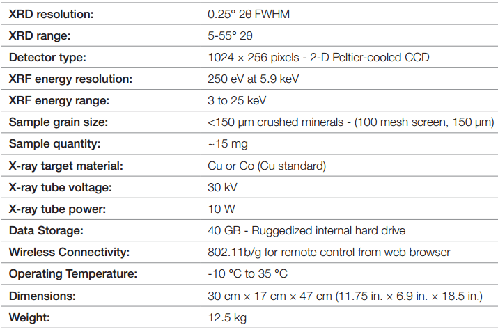
SPECIFICATIONS
XRD ANALYSER SAFETY
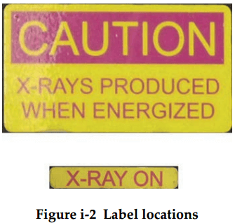
LABEL AND SYMBOLS
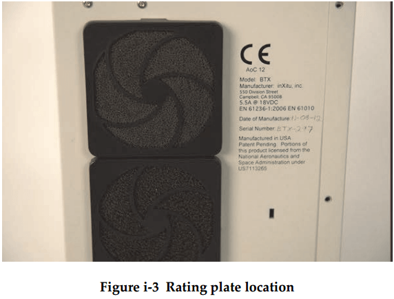
Safety-related labels and symbols are attached to the BTX II X-ray Diffraction Analyzer at the locations shown in Figure i-1 on page 1. If any of the labels or symbols are missing or illegible (see Figure i-2 on page 1), please contact Olympus.

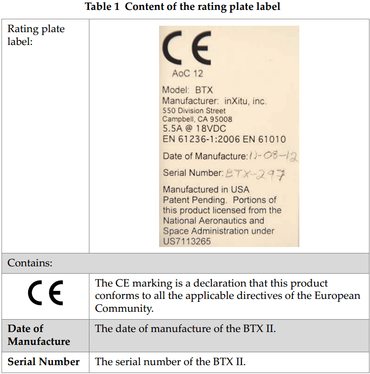
The rating plate label is located on the back of the BTX II (see Figure i-3 on page 2). The contents of the label are described in Table 1 on page 2.
IMPORTANT INFORMATION — PLEASE READ BEFORE USE
Intended Use
The BTX II X-ray Diffraction Analyzer is designed primarily for analyzing a variety of powder sample types.
Do not use the BTX II for any purpose other than its intended use. It must never be used to inspect or examine human or animal body parts.
Instruction Manual
This instruction manual contains essential information on how to use this Olympus product safely and effectively. Before using this product, thoroughly review this instruction manual, and use the product as instructed.
Keep this instruction manual in a safe, accessible location.
System Compatibility
Do not use incompatible equipment with the system
Using incompatible equipment could cause malfunction and/or equipment damage.
REPAIR AND MODIFICATION
The BTX II does not contain any user-serviceable parts.
In order to prevent human injury and/or equipment damage, do not disassemble modify, or attempt to repair the system.
SAFETY SYMBOLS
The following safety symbols might appear on the system and in the instruction manual:

General warning symbol:
This symbol is used to alert the user to potential hazard. Obey all safety messages that follow this symbol to avoid possible harm.

Radiation warning symbol:
This symbol is used to alert the user to the presence of potentially harmful ionizing radiation generated within the system. Obey all safety messages that follow this symbol to avoid possible harm.

High voltage warning symbol:
This symbol is used to alert the user to potential electric shock hazards greater than 1000 volts. Obey all safety messages that follow this symbol to avoid possible harm.
Safety Signal Words
The following safety symbol might appear in the documentation of the system:

The DANGER signal word indicates an imminently hazardous situation. It calls attention to a procedure, practice, or the like, which, if not correctly performed or adhered to will result in death or serious personal injury. Do not proceed beyond a DANGER signal word until the indicated conditions are fully understood and met.

The WARNING signal word indicates a potentially hazardous situation. It calls attention to a procedure, practice, or the like, which, if not correctly performed or adhered to could result in death or serious personal injury. Do not proceed beyond a WARNING signal word until the indicated conditions are fully understood and met.

The CAUTION signal word indicates a potentially hazardous situation. It calls attention to an operating procedure, practice, or the like, which, if not correctly performed or adhered to, may result in minor or moderate personal injury, material damage, particularly to the product destruction of part or all of the product, or loss of data. Do not proceed beyond a CAUTION signal word until the indicated conditions arc fully understood and met.
Note Signal Words
The following safety symbols could appear in the documentation of the system:

The IMPORTANT signal word calls attention to a note that provides important information, or information essential to the completion of a task.

The NOTE signal word calls attention to an operating procedure, practice, or the like, which requires special attention. A note also denotes related parenthetical information that is useful, but not imperative.

The TIP signal word calls attention to a type of note that helps you apply the techniques and procedures described in the manual to your specific needs, or provides hints on how to effectively use the capabilities of the product.
SAFETY
Before turning on the system, verify that the correct safety precautions have been taken (see the following warnings). In addition, note the external markings on the system, which are described under Safety Symbols.
WARNINGS
General Warnings
- Carefully read the instructions contained in this instruction manual before turning on the system.
- Keep this instruction manual in a safe place for further reference.
- Follow the installation and operation procedures.
- It is imperative to respect the safety warnings on the system and in this instruction manual.
- If the equipment is used in a manner not specified by the manufacturer, the protection provided by the equipment could be impaired.
- Do not perform any unauthorized modification to the system.
- Service instructions, when applicable, are for trained service personnel. To avoid the risk of electric shock, do not perform any work on the system unless qualified to do so. For any problem or question regarding this system, contact Olympus or an authorized Olympus representative.

Radiation Safety Warning
Do not open the system, disassemble, or modify any internal components. These actions could result in serious damage to the system and a health hazard to the operator.

- The mains plug shall only be inserted into a socket outlet provided with a protective earth contact. Never negate this protective action by using an extension cord (power cable) without a protective conductor (grounding).
- If there is any possibility that the ground protection could be impaired, you must make the system inoperative and secure it against any unintended operation.
- The system must only be connected to a power source corresponding to the type indicated on the rating plate.

High Voltage
The BTX II uses a 30 kV high-voltage power supply (HVPS) for X-ray generation. The permanent connection between the HVPS and the X-ray tube is sealed and shielded in such a way that no high voltage connector could accidentally get loose or disconnected inside the system. There is no high voltage risk to the user when using BTX II under normal conditions. Should you notice substantial damage to the outside of the system, or suspect any internal damage after excessive shock, DO NOT turn on the system, return it to the factory for full inspection and potential repairs.

- X-ray tubes and detectors in this instrument contain beryllium metal in the form of coated foil. In its as-supplied state, the beryllium poses no harm to the user. However, if a detector or tube is damaged, contact with small particles is possible if the instrument is breached (e.g. window broken or during window replacement). Intact skin is sufficient protection against this situation and washing with soap and water will effectively remove any beryllium contamination. If granulated beryllium imbeds in an open wound, seek medical attention.
- Instruments where the detector or tube is damaged must be returned to your local distributor or the manufacture. Care should be taken to limit the release of beryllium from the instrument
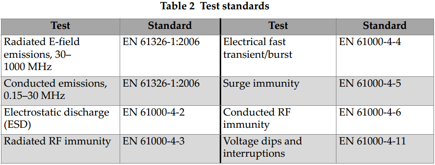
EMC DIRECTIVE COMPLIANCE
FCC (USA) Compliance
This equipment has been tested and found to comply with the limits for a Class A digital device, pursuant to Part 15 of the Federal Communications Commission (FCC) rules. These limits are designed to provide reasonable protection against harmful interference when the equipment is operated in a commercial environment. This equipment generates, uses, and can radiate radio frequency energy, and if not installed and used in accordance with the instruction manual, might cause harmful interference to radio communications. Operation of this equipment in a residential area is likely to cause harmful interference, in which case you will be required to correct the interference at your own expense.
ICES-001 (Canada) Compliance
This Class A digital apparatus complies with Canadian ICES-001.
Cet appareil numerique de la classe A est conforme a la norme NMB-001 du Canada.
Before operating your system, you must read, understand and comply with the regulations as detailed in the HC Radiation Emitting Devices (RED) regulation. Details on the regulations relevant to analytical x-ray producing devices, such as the Olympus BTX II can be found at:
http://www.canlii.org/en/ca/laws/regu/crc-c-1370/latest/crc-c-1370.html
US Compliance
The Olympus BTX II X-ray Diffraction Analyzer is compliant with US FDA CFR 1020.40. This regulation mandates radiation protection safety systems, and ensures the product is not hazardous for routine operation. US FDA CFR 1020.40 specifically details that “the provisions of this section are not applicable to systems which are designed exclusively for microscopic examination of material, for example, X-ray diffraction, spectroscopic, and electron microscope equipment or to systems for intentional exposure of humans to X-rays.” Olympus abides by this section in an effort to take all reasonable steps to eliminate radiation exposure to operators.
Before operating your system, you must read, understand and comply with the regulations as appropriate for your state. Contact your state department of public health, radiation protection, for the specific guidelines associated with the operation of a “minimal threat” device such as the Olympus BTX II product.
CE (European Community)
EN 61010-1: Safety requirements for electrical equipment for measurement, control and laboratory use – Part 1: General requirements (1EC 61010-1:2001):
EN 61326-2006: Electrical equipment for measurement, control and laboratory use – EMC requirements (IEC 61326-1:1997 + IEC 61326-1/A1:1998 + IEC 61326-1/A2:2000 + Annexes E and F of IEC 61326:2002 + Corrigendum:2002);
Warranty Information
Olympus guarantees your Olympus product to be free from defects in materials and workmanship for a period of one year. The Olympus warranty only covers equipment that has been used in a proper manner, as described in this instruction manual, and that has not been subjected to excessive abuse, attempted unauthorized repair, or modification.
Inspect materials thoroughly on receipt for evidence of external or internal damage that might have occurred during shipment. Immediately notify the earner making the delivery of any damage, because the carrier is normally liable for damage during shipment. Retain packing materials, waybills, and other shipping documentation needed in order to file a damage claim. After notifying the carrier, contact Olympus for assistance with the damage claim and equipment replacement if necessary.
This instruction manual explains the proper operation of your Olympus product. The information contained herein is intended solely as a teaching aid and shall not be used in any particular application without independent testing and for verification by the operator or the supervisor. Such independent verification of procedures becomes increasingly important as the criticality of the application increases. For this reason, Olympus makes no warranty, expressed or implied, that the techniques, examples, or procedures described herein are consistent with industry standards, nor that they meet the requirements of any particular application.
Olympus reserves the right to modify any product without incurring the responsibility for modifying previously manufactured products.
Technical Support
Olympus is firmly committed to providing the highest level of customer service and product support. If you experience any difficulties when using our product, or if it fails to operate as described in the documentation, first consult the user’s manual, and then, if you are still in need of assistance, contact our After-Sales Service. To locate the nearest service center, visit the Service Centers page at: http://www.olympus-ims.com.
BTX II X-RAY DIFFRACTION ANALYZER OVERVIEW
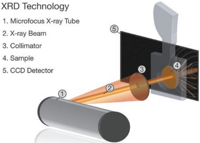
The Olympus BTX II is a benchtop XRD/XRF (X-ray diffraction / X-ray fluorescence) system designed primarily for analyzing a variety of powder sample types. Phase identification is obtained by comparing the diffraction signature of a sample with a database of XRD mineral patterns. The addition of XRF allows easy screening during the phase identification process and can alleviate rare uncertainties.
The BTX II uses a low power X-ray source and 2-D charge coupled device (CCD) detector to obtain XRD data, and a low power X-ray source and a silicon drift detector (SDD) to obtain XRF data. Single minerals or simple mixtures are typically identified after just a few minutes of integration.
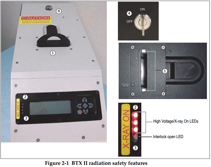
The BTX II incorporates the following independent safety protection circuits:
- Power key switch — Key must be inserted and in the ON position to turn the system on.
- X-ray warning indicators — LEDs on the front panel illuminate when X-rays are being generated, and also during the power on sequence.
- Sample carrier safety interlock — High voltage from the power supply is interrupted and generation of X-rays ceases if the sample carrier is removed during system operation.
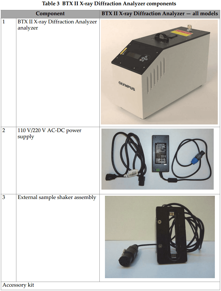
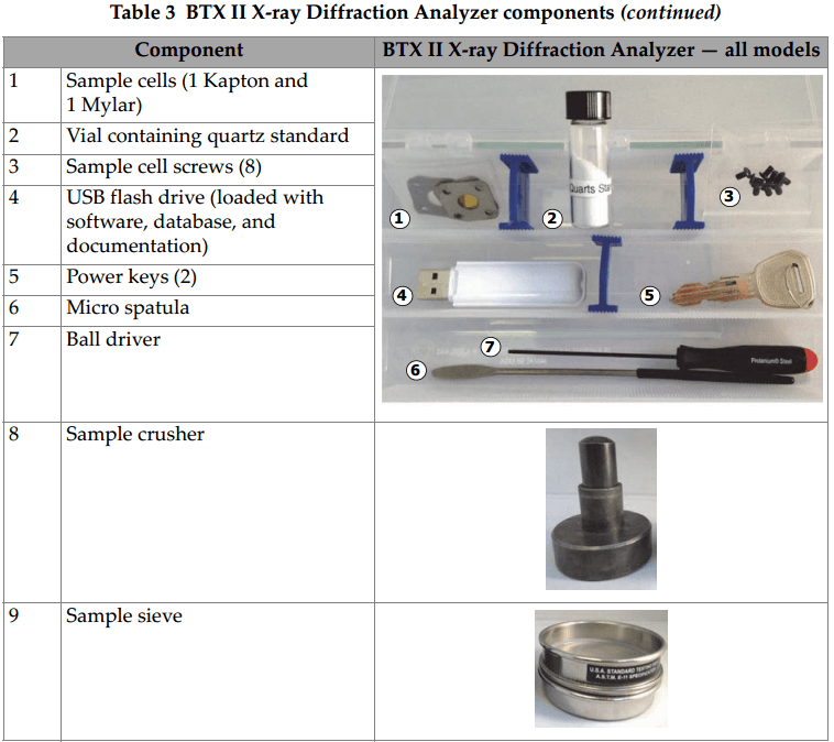
Packing List
The following table lists the BTX II X-ray Diffraction Analyzer components (see Table 3 on page 10).
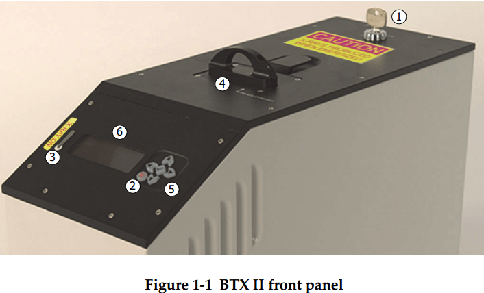
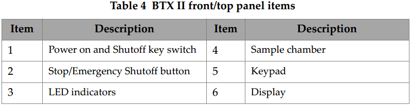
Front/Top Panel
The front and top panels are where all BTX II controls, indicators, and the sample chamber are located (see Figure 1-1 on page 12 and Table 4 on page 12).
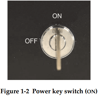
Power Key Switch
Turn the power key clockwise to turn the BTX II on (see Figure 1-2 page 12).
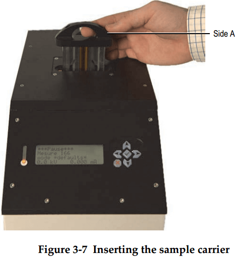
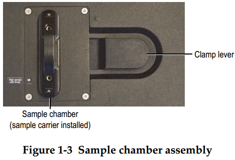
Sample Chamber
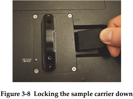
The sample chamber is located in the center of the top panel. The clamp lever locks and unlocks the sample carrier (see figure 1-3 on page 13).
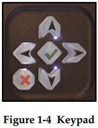
Keypad
The keypad allows you to make selections on the main display to set up and run tests, and save results (see Figure 1-4 on page 13).
Stop/Emergency Shutoff Button
The Stop/Emergency Shutoff button allows you to stop an in-progress test, turn off system power in an emergency, or cancel a selection when using the keypad and main menu to set up tests (see Figure 1-5 on page 13).

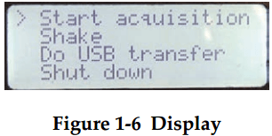
Display
The display shows selections for setting up and monitoring tests (see Figure 1-6 on page 14).
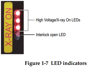
LED Indicators
The LED indicators show the status of the high-voltage power supply. X-ray tube, and safety interlocks (see Figure 1-7 on page 14).
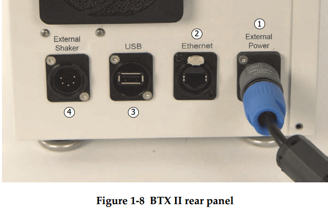
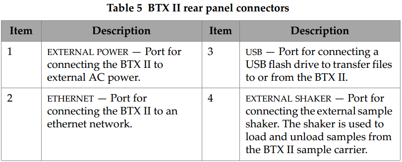
Rear Panel
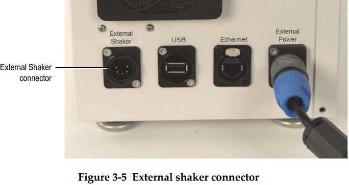
The rear panel is where all BTX II connectors are located (see Figure 1-8 on page 14 and Table 5 on page 15).
SAFETY INFORMATION
This chapter contains important safety information for using the BTX II X-ray Diffraction Analyzer.
Radiation Safety Information
The fundamental principle in radiation protection is that all radiation exposures should be maintained as low as reasonably achievable (ALARA). This is referred to as the ALARA principle. The three key factors which influence an individuals radiation dose from a given source are time, distance and shielding. Control of these factors is the key to keeping the radiation dose ALARA.
- Time
The most direct way to reduce radiation dose is to reduce the time spent working with or in the vicinity of radiation sources. If the exposure time is cut in half, the dose will be reduced by the same fraction. - Distance
Distance can effectively reduce a radiation done. When the working distance from the radiation source is increased by a factor of two, the dose received from that source is reduced by a factor of four. This is referred to as the inverse square law, i.e., the radiation intensity from a point source decreases by the square of the distance from the source. - Shielding
Shielding is any material used to reduce the intensity of radiation by absorbing or attenuating the radiation coming from the source.
Do not open the system, disassemble, or modify any internal components. These actions could result in serious damage to the system and a health hazard to the operator.
Safety Interlocks
The BTX II uses an X-ray tube that produces ionizing radiation up to 30 keV at very low power (10 W) as compared to laboratory XRD systems (typically greater than 1 kW). The BTX II system is designed with internal X-ray shielding to fully protect operators and internal components.
The radiation producing components are completely contained within the system housing and constructed in such a way that no measurable radiation is detected during operation. No beam alignment nor X-ray beam calibration by the operator is required. There is no reason for any BTX II operator to bypass any radiation safety switches. The BTX II fully complies with the FDA CFR, section 1020.40 including safety interlocks and radiation measurements. The BTX II has no measurable radiation leakage from any surface during operation. This is because of the shielding of the X-ray generation and detection components, and the low operating potential and power of the X-ray generation source.
The BTX II incorporates several independent safety interlock circuits to protect the operator. See Figure 2-1 on page 18 and Table 6 on page 18.

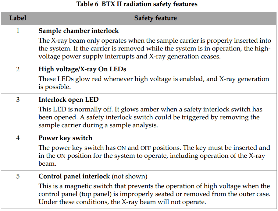
Figure 2-2 on page 19 shows the LEDs described in Table 7 on page 20. Table 7 describes the behavior of the LEDs in relation to X-ray emissions.
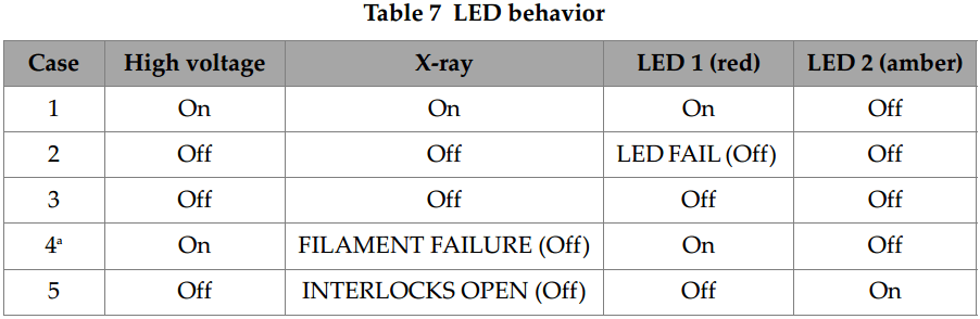
a. A current drop during a measurement can be related to a filament failure. In such a case, please contact the Olympus After-Sales Service. If the filament fails, the X-ray automatically turns off while the high voltage remains active. The X-ray tube is specifically designed to withstand such a breakdown and the electrical safety is maintained.
RADIATION DOSE MEASUREMENTS
Radiation dose measurements were made to document any possible ionizing radiation dose to a typical operator of the BTX II. The measurements were made using a calibrated Ludlum Model 9-3 Radiation Ion Chamber. This chamber is capable of measuring low energy X-ray fields to within plus or minus 20 % of true value above 10 keV, with a typical counting range of 0 to 200 mR/hr.
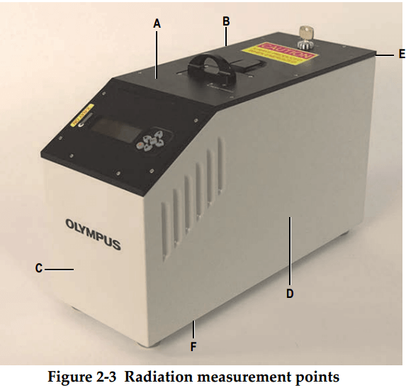
During testing, the BTX II X-ray Diffraction Analyzer was operated at X-ray tube conditions which are standard for all testing materials (30 kV, 330 µA). Radiation dose measurements were made at specific locations at the base, back, front, and sides of the system.
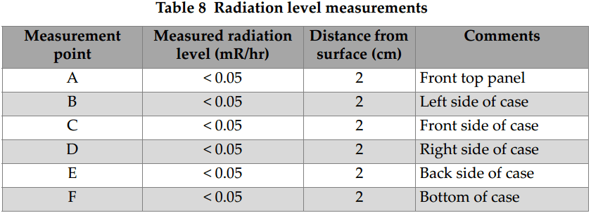
Radiation dose measurements around the perimeter of the system, at a distance of less than 2 cm, yielded no measurable radiation levels (less than 0.2 mR/hr). This level is well within acceptable levels of exposure to the general public. When properly set up and operated, there is no exposure in excess of the typical dosage to the general public of naturally occurring sources of ionizing radiation.
Figure 2-3 on page 21 shows the radiation dose measurement points. The radiation levels measured at these points are reported in Table 8 on page 21. All measurements were made at maximum 30 kV, 330 µA power setting.