This paper discusses the design and use of the ferric chloride trap. The operation is simple and self-adjusting. The rock-salt column is self-cleaning and will remove ferric chloride, other impurity chlorides, and dust from gaseous titanium tetrachloride. The losses of titanium are low, and the molten mixture is easy to handle.
The trap is placed in the hot gas stream between the chlorination reactor and the condenser. Virtually all of the iron is removed by the trap. The condensed titanium tetrachloride is free of suspended solids and contains only a trace of iron. Four examples are given of the use of the ferric chloride trap in chlorination of impure titaniferous materials.
In the Kroll process, ductile titanium metal is produced by reducing titanium tetrachloride with magnesium metal. In commercial practice, titanium tetrachloride is produced by chlorinating titaniferous materials in the presence of carbon. In 1957 most producers were using rutile, and virtually all plants were designed for its use. About four-fifths of the domestic consumption of rutile was imported from Australia. The Bureau of Mines, under provisions of contract DMP-116 with the General Services Administration, studied electrosmelting of domestic ilmenites and titaniferous magnetites to produce high-titanium slags with pig iron as a byproduct. Under the same contract, chlorination studies also were being made of these slags. Smelting was done at the Northwest Electrodevelopment Experiment Station, Albany, Oreg., and chlorination at the Electrometallurgical Experiment Station, Boulder City, Nev.
This report describes one phase of laboratory chlorination studies and deals with the design and performance of a trap that was developed to remove ferric chloride and several other impurity chlorides from the titanium tetrachloride gas stream before it condenses. The trap simplifies chlorinating titaniferous materials containing more impurities than rutile (for example, slags) and may be adaptable to chlorinating ilmenite. In commercial practice, the titanium tetrachloride, ferric chloride, and other impurities are condensed together and distilled off the semipure tetrachloride in a sludge boiler.
Ferric Chloride Trap
The basic flowsheet of a chlorinator for titaniferous materials consists of a reactor and a condenser with accessory equipment, such as feeders, controls, etc. The hot gases leaving the reactor contain the volatile reaction products. The ferric chloride trap is placed in the hot-gas stream between the reactor and the condenser. Its function is to remove the bulk of the impurity chlorides before the titanium tetrachloride is condensed.
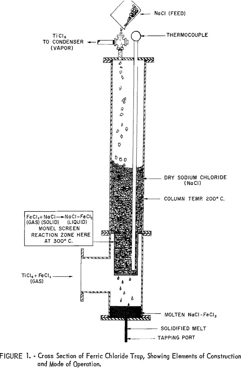
The experimental data for this report were obtained by continuous (24-hr.-per-day) operation of a laboratory chlorinator. The reactor was a 4-inch (inside-diameter) by 24-inch quartz tube heated by an external, electric, resistance furnace. It was operated as a moving-bed unit with small screw feeders on the top and bottom. The chlorine was fed into the bottom, and the gaseous reaction products passed out of the top to the ferric chloride trap (See fig. 1.) The titanium tetrachloride from the ferric chloride trap was condensed in a vertical, water-cooled, 1-½ inch, black-iron pipe, which drained into a glass receiver.
The reactor was fed a mixture of calcined petroleum coke and titaniferous material (slag or ilmenite) at the top while chlorine was introduced at the bottom. The average particle size of the feed was approximately 65-mesh. The principal reaction (1) between titanium dioxide and chlorine and numerous side reactions between the various impurity oxides and chlorine took place in the hot zone at 800° to 1,200° C.
13TiO2 + 26Cl2 + 20C → 13TiCl4 + 14CO + 6CO2………………………………………………………….(1)
The hot gases leaving the reactor contain the volatile reaction products, which depend upon the material being chlorinated and are primarily TiCl4, FeCl3, AlCl3, MnCl2, FeCl2, CO, CO2, COCl2, HCl, SiCl4 VOCl3, and traces of complex organic chemicals.
As the impurities increase in a titaniferous material to be chlorinated the impurity chlorides in the hot gases also increase. Most of these chlorides are solids and are only slightly soluble in liquid titanium tetrachloride at the temperatures of condensation. Therefore, when direct condensation takes place, without the ferric chloride trap, a slurry is formed. A titanium tetrachloride-ferric chloride slurry containing 10 percent or more solids is thick, viscous, and difficult to handle.
The ferric chloride trap shown in figure 1 is a column containing coarse anhydrous rock salt (NaCl) supported on a screen. The hot-gas stream enters the column at a right angle below the screen. Directly below the screen is a chamber with a tapping port. The gases entering the column are maintained at or above 300° C. by electric heating elements to prevent condensation of solid chlorides. The rock-salt column is heated to 200° C. to permit free passage of TiCl4 gas. The principal action in the trap is between ferric chloride (a gas) and sodium chloride (a solid) to form a molten mixture that is a liquid at the operating temperatures:
FeCl3(gas) + NaCl (solid) → FeCl3-NaCl (liquid)

The molten mixture forms on the rock salt at or directly above the screen. This mixture 3 which is fluid above 160° C., drains away from the rock salt into the heated chamber below the screen, from which it is periodically tapped. Tapping is done by removing the cap from the end of the port and melting the plug of solidified salt. The molten mixture drains completely, and the port is recapped. Additional rock salt is added to the top of the column as needed.
Molten mixtures of ferric chloride and sodium chloride have been studied by H. F. Johnstone, I. J. Krchma, and others. S. L. May and V. A. Neiberlein, of the Bureau of Mines, have also made such studies. The phase diagram for ferric chloride-sodium chloride shows the low-melting eutectic at 46 mole-percent (23.5 weight-percent) sodium chloride and 158° C. The curve is steep at the eutectic composition. At 200° C. the composition ranges from 42 to 48 mole-percent of sodium chloride.
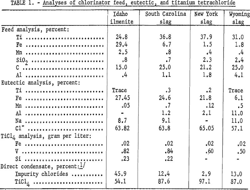
Table 1 summarizes the results of chlorinating Idaho ilmenite, South Carolina slag, New York slag, and Wyoming slag using the ferric chloride trap. The direct-condensate figures are the calculated analyses of the slurries that would be condensed if the ferric chloride trap were not used. The impurity-chloride figures are in effect, the percentages of solids in such slurries.

The eutectic analysis shows that the ferric chloride trap is effective in removing the aluminum and manganese, as well as the iron. Basically, the trap can be expected to remove any vapors that condense at 200° C. and above, also dust particles that are carried mechanically in the gas stream. The impurities, such as silicon and vanadium, which form chlorides with boiling points near titanium tetrachloride (136° C.) or below, pass through the trap and are either condensed with the titanium tetrachloride or exhausted with the noncondensable gases.
