Table of Contents
Mixers are being applied with increasing frequency to problems in the metallurgical industries. The increase represents in part the modernization of mechanical equipment used through the application of unitized drives, modern electric motors and speed reducers, and recently developed materials of construction. Some applications have resulted from process changes and the use of techniques for operations similar to those that have been demonstrated and proven in the chemical industry. Still more applications are being developed through the use of fluid-dynamics principles not previously recognized as applicable to these operations.
Fluid Motion
The fundamental problems of mixing and agitation of liquids have to do with the mechanics of fluid streams and the means by which they are
moved. Mixing is accomplished by material transfer through momentum transfer and turbulence. Agitation is the result of turbulent fluid motion. In most large-scale mixing operations, a rotating impeller is used to produce liquid flow. Turbulence may be generated in four ways: by the action of the impeller blade on the liquid; by the rubbing of liquid on the walls of the tank; by the passage of the liquid around an obstruction; or by high velocity streams moving adjacent to low velocity streams. This latter mechanism involves a flow-velocity discontinuity and plays the largest single role in the creation of turbulence and agitation by propeller and turbine-type mixers.
The mixing tank should be cylindrical with axis vertical, the bottom may be flat, dished out, or a shallow cone. Liquid depth equal to the tank diameter is good practice, but may be as deep as two diameters. In large tanks the liquid depth may be less, but good mixing cannot be obtained if the depth is too low. Square or rectangular tanks are to be avoided because it is often difficult to secure adequate fluid motion in the corners.
Flow Patterns for Mixing
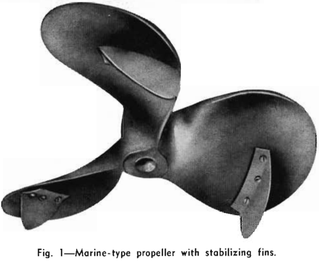
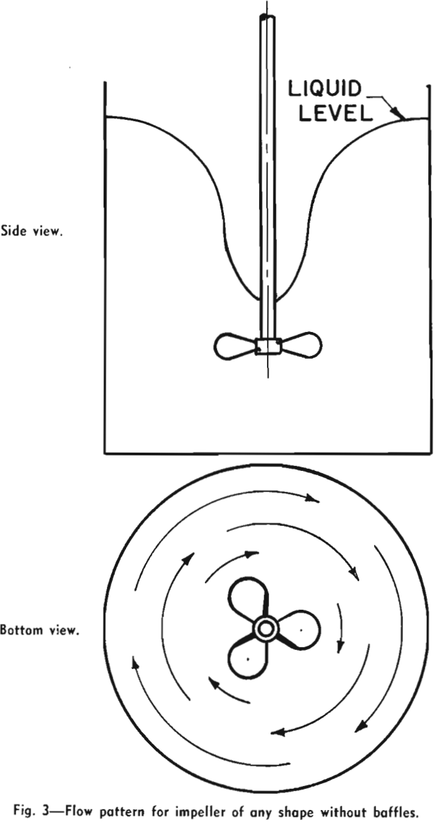
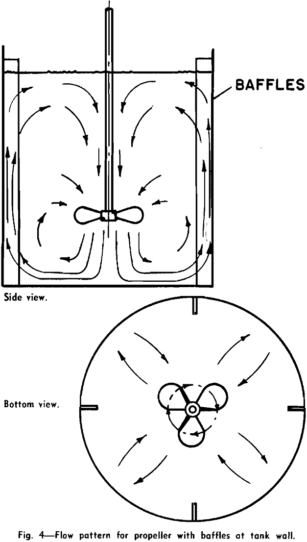
The impeller causes fluid motion and generates, together with the wall, the principal lines of flow through the liquid. When a single impeller of any shape or size is rotated on the center line of a smooth-wall cylindrical tank, the flow motion which is set up is a rotary swirling or vortex motion. The flow is circular and there is practically no vertical motion. The liquid moves as in a merry-go-round, and there is little chance for mixing because liquid is not forced sideways or vertically. If, however, there are obstructions on the wall of the tank or elsewhere, different impellers will give either of two different principal types of flow patterns. The marine-type propeller produces axial flow: the flow leaves the impeller in the direction of the axis of rotation. The flow pattern is illustrated in Fig. 4. It should be noted that there are vertical and lateral-flow lines: liquid is moved up, down, and horizontally, providing good top-to-bottom turnover, and this motion is conducive to good mixing. Note that propellers are almost always operated to discharge downward, and, when two are used on one shaft, they both discharge downward.
When flat paddles or turbines are rotated with obstruction in the liquid, the liquid moves from the turbines in a plane perpendicular to the axis of rotation. Such motion has been called radial motion, and any impeller which generates this type of flow is classed as a radial-flow impeller.
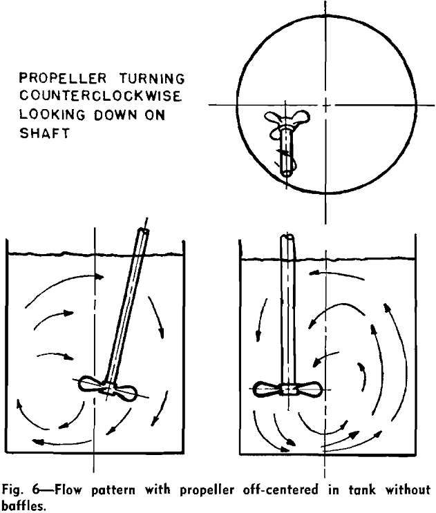
Ordinarily, impeller shafts enter through the top surface of the liquid, centered, and baffles are used. However, propellers can be used to give axial flow, top-entering without baffles, or side-entering without baffles, in off-centered positions.
Mixing Requirements for Processing
The first consideration for mixing in a process is the choice of the flow pattern best suited to the operation. If solids are to be suspended, vertical flow currents must be developed to oppose the settling velocity of the particles, as in Figs. 4, 5, and 6. Turbines and paddles are effective at low rotational speeds and are preferred for large tanks, since they permit the use of long shafts without submerged bottom bearings.
The power requirements for mixing depend upon the flow pattern desired, the velocities of flow which must be obtained at particular parts of the liquid, and the turbulent energy required. The velocity of flow is dependent upon the quantity of material in motion and the area through which it moves. Thus, a large quantity of flow produced by a small-diameter propeller will result in high velocities over small areas. Such flow will produce high intensity turbulence, but the scale of the turbulence may be low. On the other hand, low velocities of flow may be produced by a large-quantity flow produced by a large-diameter impeller.
Data are available for the flow produced in baffled tanks by square-pitch three-blade

marine-type propellers manufactured by Mixing Equipment Co., Inc.,
Q = K N D³…………………………………………………………………(1)
where Q is the flow in cu ft per sec, N is rps, D is the propeller diameter, ft, and the constant K for water is 0.4. The equation shows that flow varies directly with impeller speed, and with the cube of the diameter. If propeller size is doubled and speed kept constant, the flow will be increased eight times.
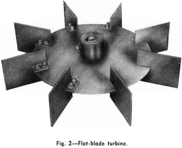
Eq. 1 can be used for flow in baffled tanks from flat-blade turbines, and other-shape impellers by use of a proper value for the constant K. The value of K for a turbine with six flat blades, like that shown in Fig. 2, is 0.5.
Power Required to Drive Impellers
The power required to drive a rotating impeller is a function of its shape, size (D), speed (N), and location, and of the fluid properties (density p and viscosity µ), and of the tank fittings and configuration.
When the value of (D²Np/µ), the Reynolds’ number, is greater than 5000, and the liquid surface does not swirl in a vortex but has a flow, it can be safely assumed that the fluid motion is fully turbulent. For these conditions, power can be computed by
P = K/gc p N³ D5…………………………………………………………….(2)
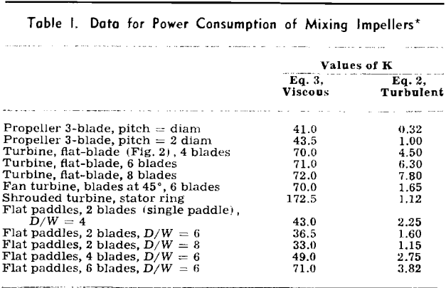
where P is power in ft-lb per sec, gc is the gravity constant, and K is a constant (see Table I). The equation shows that for baffled conditions, if the speed of any impeller is doubled, the power required to turn it will be increased (2)³, or eight times. Also, if a dimensionally similar impeller is twice the size of a smaller one, it will require (2)5, or 32 times the power to rotate it at the same speed as the smaller one.
For viscous conditions, when the Reynolds number is less than 10,

The power imposed by an impeller results in flow against a total head
P = Q p H……………………………………………………………………………[4]
where H is the total head in feet, and includes all static, pressure, velocity, and turbulent heads. Initial turbulence in a stream from an impeller is proportional to H; thus, the same amount of power can be applied to produce a large flow and small head (or turbulence), or a small flow with large head (or turbulence).
For example, a propeller of some size operating at 420 rpm will produce one unit of flow at one unit of head. If a large impeller, 1.52 times the diameter of the first one, is operated, it must turn at 210 rpm to impress the same power. This will result in an increase in flow of 74 pct (Q = 1.74) and a decrease in head to 58 pct of that present with the smaller propeller. These relations can be derived from Eq. 2 resulting in
Nr = Dr -5/3………………………………………………………………….[5]
where the subscript r indicates the ratio of large size to small size. These relations are the basis for the selection of proper mixing and agitation equipment and for scale up of experimental results to large-size equipment.
