Table of Contents
The iron oxide pelletizing industry is very energy intensive and relies heavily on natural gas to fire pellet-indurating furnaces. Approximately 75 million long tons of iron oxide pellets are produced in the United States each year, requiring a fuel input of about 55 billion ft³ of natural gas. During the past several years the industry has seen its gas supplies interrupted while costs have tripled. In the short term, supplies are likely to become even more restricted, interruptions longer and more frequent, and costs further increased. In the long term, even if gas is available, it will undoubtedly be a high-cost commodity. Presently, fuel oil is the only proven alternative, but it is similarly restricted and costly, and cannot be relied upon as a future base fuel.
To face the challenge of dwindling premium fuel supplies to an industry so basic to the Nation’s economy, the Bureau of Mines and others had previously examined direct coal firing as an alternate energy source. Pulverized coal firing tests at both pilot plant and commercial scale have shown that no single coal type is compatible with all three of the commercial pelletizing systems.
For the grate-kiln process, only premium-quality eastern coals with ash softening temperatures in excess of 2,600° F have shown promise; such fuels are now being used in a number of taconite plants in Minnesota and Michigan. Coals having ash with low fluid temperatures are required for the straight-grate process, because the new prototype design consists of external “wet bottom” combustion chambers. With this system, however, slag flow from the bottom chamber and slag attack and/or wear on the refractory lining are potential problems. The shaft-pelletizing furnaces have not yet been adapted to direct coal firing. The major problems are the need to distribute powdered coal to a large number of combustion chambers and the potential for blockage of the inaccessible refractory passageways with coal ash. The general conclusions regarding direct coal firing for iron ore pelletizing are that, although it can be used in some systems, coal selection will be restrictive, premium coals may have to be used, and, with the required plant modifications and increased refractory costs, it may be no more economical in the long run than some form of coal gasification.
A study funded by the Bureau of Mines and conducted by the Davy McKee Corporation, pointed out that with currently available technology, production of a hot, raw, low-Btu gas generated by an atmospheric producer would be an economically favorable alternative to natural gas or oil. An onsite facility would provide a high overall thermal efficiency and would also minimize the capital costs of the coal gasification plant. The low-Btu gas produced could be used in all three commercial pelletizing systems without excessive structural or equipment modifications; however, in the shaft furnace plant, the retrofit costs could be substantial because of the gas pressure required and number of burners utilized- Regardless of the pelletizing system, the fuel distribution lines, burners, and some burner instrumentation will have to be replaced to handle the higher fuel gas volumes and lower air volumes. The onsite system of gas production would give the pelletizing industry a wider selection of coals and would be decidedly cost effective in northern Minnesota, Michigan, and Wisconsin, if the not- too-distant, low-sulfur western subbituminous and lignite coals could be used.
Although the study indicated that the use of low—Btu gas for pellet induration appears technically feasible, its practical aspects must first be demonstrated in a pilot plant.
The Bureau, in cooperation with the Department of Energy (DOE) and 20 U.S. firms with interests in iron ore, coal, gas, and process design, has formed a cooperative, cost-sharing group known as the Mining and Industrial Fuel Gas Group (MIFCA) to promote development and demonstration of low-Btu coal gas as an alternate fuel for mineral processes and other industrial applications. During the past 2 years performance tests have been conducted with a commercial-size, 6.5- ft-diam Wellman-Galusha gasifier at the Bureau of Mines Twin Cities (Minn.) Research Center. The gasifier is owned by one of the industrial cooperators; the facility and construction were provided with Government funding: and operations: materials, and equipment are shared by all. Operation of the coal gasifier is the responsibility of the MIFGA industrial cooperators. DOE is interested in gasifier operations and technology, while the Bureau is interested in demonstrating the use of the low-Btu coal gas as part of its program on alternate fuels for minerals and metallurgical processes. Currently, raw, low-Btu coal gas is being tested in the Bureau’s pilot plant rotary kiln to demonstrate heat hardening of iron oxide pellets for blast furnace feed stock, as well as in a 21-ft-long combustion chamber to evaluate low-Btu gas burner designs. Both the pelletizing kiln and the combustion test chamber are connected to the gasifier structure. The Environmental Protection Agency (EPA) has monitored some of the tests to characterize various gaseous, liquid, and solid streams in the process in order to develop new source performance standards (NSPS) for low-Btu coal gasification.
This paper describes the major findings from a 30-day around-the-clock performance test conducted from October 23 to November 21, 1980, with a raw lignite feed stock from North Dakota. Descriptions of the gasifier and pellet plant facility and operations are presented along with an analysis of the performance of raw, low-Btu lignite gas for indurating hematite pellets in a rotary kiln.
Acknowledgments
The author would like to express his appreciation to the Mining and Industrial Fuel Gas Croup (MIFGA) members who participated in the lignite gasifier operations, to American Natural Resources for supplying the Indianhead lignite, and to the Burlington Northern Railroad for transporting it from North Dakota. Special recognition is given to Mr. George Hamilton, Sr., George M. Hamilton and Associates, Inc. (DOE Consultant), for his close guidance and direction throughout the program.
Plant Description
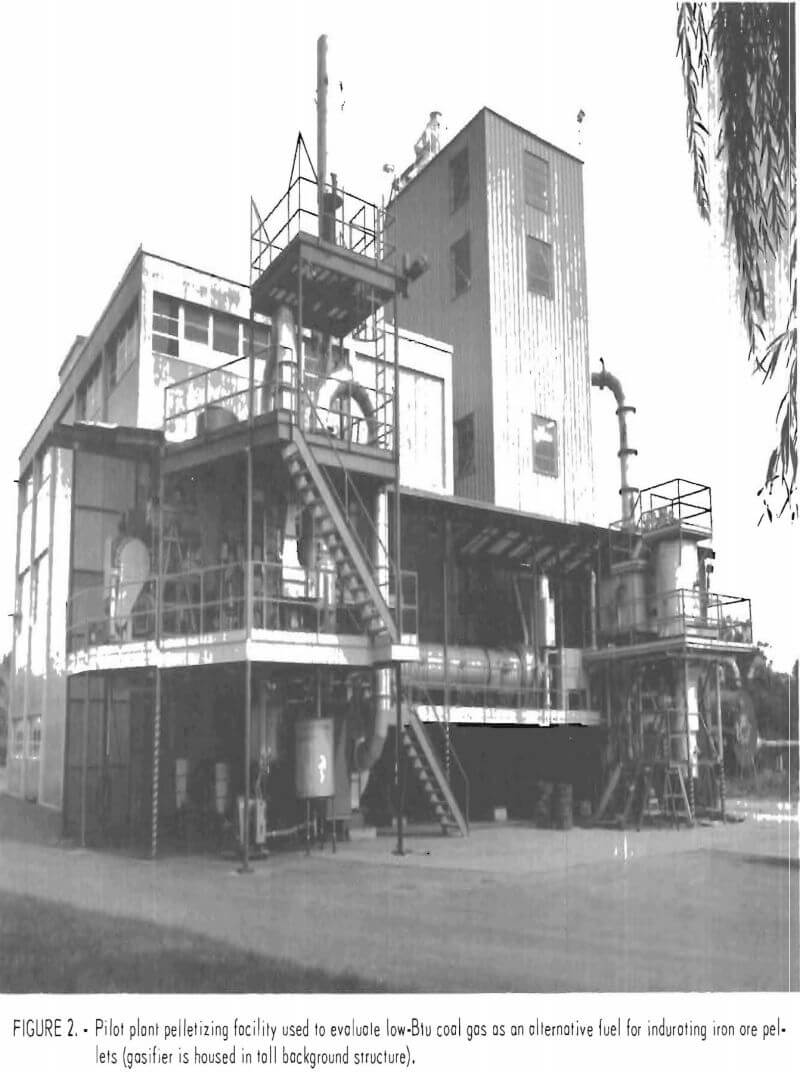
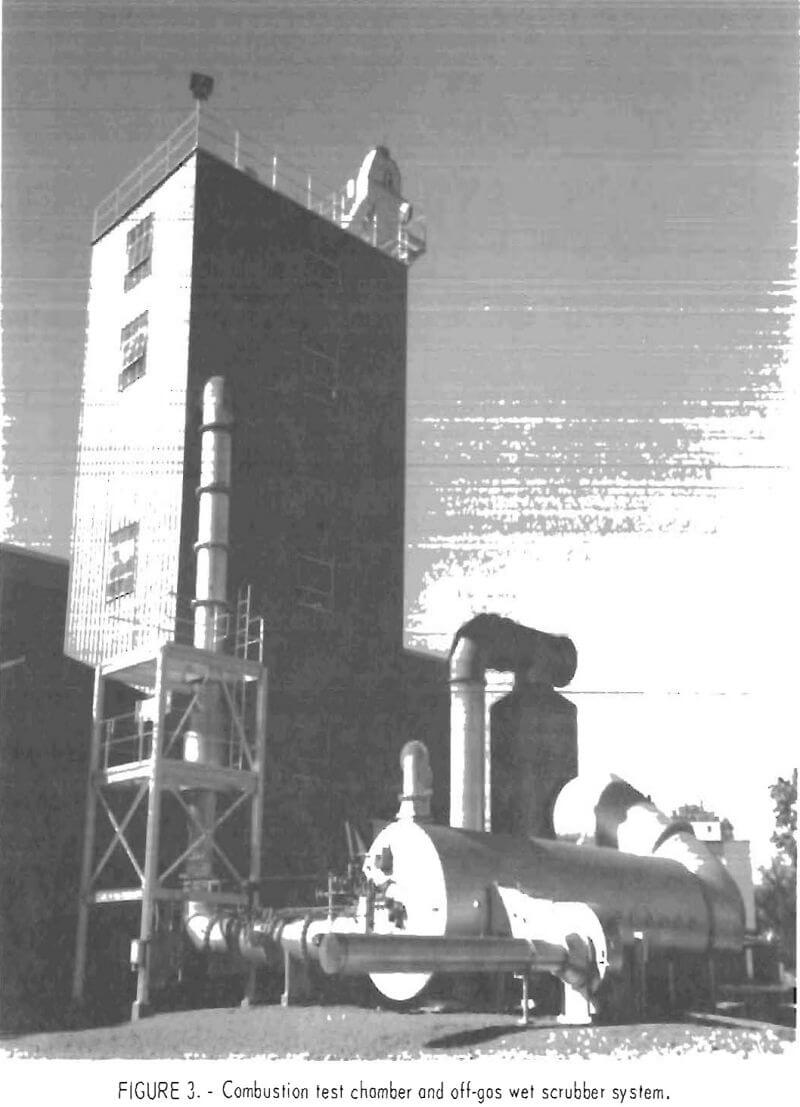
The Bureau’s pilot plant facility, shown diagrammatically in figure 1, consists of a pelletlzing plant, a gasifier, and a combustion test chamber. The gasifier is housed in a tall metal structure located adjacent to the pelletlzing kiln (fig. 2) and the combustion test chamber (fig. 3).
Pelletizing Plant
The pelletizing facility is a fully integrated pilot plant capable of taking iron ore concentrate through all pelletizing steps of balling, drying, pre-heating, indurating, and cooling. Plant capacity is nominally 900 lb/hr of dry feed. The balling circuit consists of a table feeder for concentrate, a screw feeder for bentonite, a belt-type paddle mixer for blending the bentonite binder with the concentrate, and a 6-ft-diam two-step pelletizing disk to form the green pellets.
The green pellets are first dried and then preheated (partially hardened) on a 1-ft by 10-ft-long traveling grate containing one updraft drying zone and two downdraft preheat zones. Pellets are then indurated in a 34-in-diam by 35- ft-long rotary kiln pitched at a slope of ¼ in/ft and rotating at a speed of 1 rpm. A 4.5-in dam at the discharge end allows a maximum pellet loading of about 11 pct. The kiln hot zone is lined with 70-pct-alumina refractory brick for a distance of 18 ft from the discharge end; the balance is lined with heavy-duty fireclay brick. Six thermocouples in Inconel protection tubes are positioned throughout the kiln length. The thermocouples are mounted peripherally with their measuring junctions 3 in from the kiln lining, and electrical contact is made through sliprings.
The kiln discharge end is fitted with an air-cooled, stainless steel hood
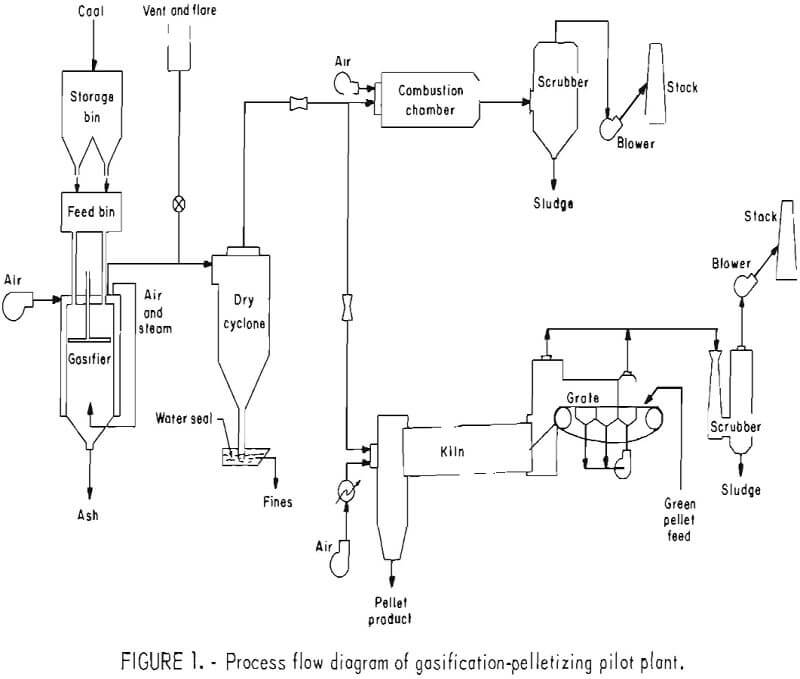
that houses the low-Btu gas burner. The face of the burner is 22 in from the discharge end of the kiln. Hot pellets exiting the kiln are retained in a refractory-lined shaft cooler. Air from the kiln hood flows up through the hot pellet bed and supplies preheated, excess air to the kiln. Off gases from the kiln and grate are drawn into a wet Venturi scrubber before finally venting into the atmosphere.
The low-Btu gas kiln burner is an axial-flow-type unit with a capacity of 3.5 million Btu/hr and is designed to operate at a fuel gas pressure of 1 in (water column). Combustion air supplied to the burner can be preheated up to 840° F. Gas flow is controlled by kiln temperature, and the airflow is controlled by a fully electronic, flow-ratio control scheme. Producer gas flow is measured with a “low loss” Venturi flow element located in the 8-in gas duct to the kiln and a mass flow computer. Pellet plant instrumentation and controls are centrally located in a control room. Temperature and most of the pressure and flow data are obtained with a data logger and are computer processed later.
Tests were conducted for 5 days, 24 hr a day. In each test, approximately 50 tons of hematite filter cake concentrate, obtained from a commercial iron ore beneficiation plant, was processed into pellets.
Gasification Plant
The gasifier is a Wellman-Galusha 6.5 ft-diam, single-stage, fixed-bed, water-jacketed atmospheric pressure producer with a water-cooled agitator arm. The unit has a nominal capacity of 1.5 tons/hr of bituminous coal, or approximately 30 million Btu/hr.
In the Twin Cities facility, nominal minus 2-in coal is first fed into a hopper with an end loader and then conveyed to a vibrating screen to remove the minus ¾-in fines. The minus 2-in, plus ¾-in coal is then transported by a bucket elevator to a storage bin on the top floor of the gasifier building. The storage bin is instrumented with load cells and has a capacity of 10 tons. Coal is periodically dumped from the storage bin into the feed bin by cycling valves. The feed bin is a double-lock type with a 5-ton storage capacity. The gasifier is continuously choke-fed from the feed bin through two 10-in-diam feed pipes by keeping the bottom coal lock valves open and the top one closed. When more coal is added to the feed bin (at least once per hour) the coal lock valves are cycled (bottom closed, top open) and the storage bin valves are closed. The sequence is then reversed to restore operations.
Two separate control systems are provided for combustion air saturation; that is, the conventional method and an auxiliary steam injection. In the conventional system, water vapor is self-generated by passing the air over the surface of the heated water in the gasifier cooling jacket. The air saturation temperature is automatically maintained by controlling the water flow through the jacket. In the second method, steam from an auxiliary boiler is injected directly into the combustion air. Saturation air flow is provided with a 16-oz blower and is measured with an annubar flow element and automatically controlled. Saturation temperature is measured with a platinum resistance thermometer (RTD) and is also automatically controlled.
The producer gas flows through a refractory-lined, dry cyclone dust collector with a water-seal dust catcher and is then transmitted through a 24-in-ID duct to the combustion chamber and an 8-in-ID duct to the pelletizing kiln. Both ducts are lined with 4 in of refractory. Larger particulates in the gas fall to the bottom of the cyclone into a water quench trough. The quenched particulates are scraped out of the trough, passed over a dewatering screen, and discarded.
Between the gas off-take and cyclone is a 10-in vent stack containing a hydraulic-actuated, double-wedge disk gate valve. At the top of the stack is an ignitor-incinerator consisting of a vertical, 3-ft-diam combustion chamber and a natural gas burner to ignite the gases during emergency flaring or to completely combust the small amount of gases generated during banking. During normal operations, the vent valve is kept closed.
Ash is continuously pushed through the vertical spacings between the two-tier grate and falls into a cone-shaped ash hopper. The ash is periodically “sluiced” from the ash cone through a 14-in pneumatically actuated valve into an ash receiver that is suspended from load cells and acts as a double-lock hopper, insuring minor pressure loss from the gasifier during ash removal.
Fire test measurements are made every 2 hours by inserting ¾-in-diam by 11-ft-long steel bars into the fuel bed through each of the seven pokeholes positioned around the top of the producer. The bars, withdrawn after several minutes, show the location of the hot zone. Since the ash depth produces no color on the bar, a reading of the ash depth up to the incandescent zone is easily measured. The pokeholes are fitted with steam-injected pressure-tight covers to prevent gas leakage when the bars are inserted.
Instrumentation and controls for the gasifier are centrally located in a control room adjacent to, but isolated from, the main operating floor of the gasifier building. Continuous strip-chart recordings are made of the airflow, saturation temperature, “fire-loss” pressure (pressure drop across the bed) and gas offtake temperature. A fully automated gas chromatograph with a thermal conductivity detector provides a producer gas analysis every 25 min. The gas sampling and conditioning system is designed to remove tar, oil, and moisture and to deliver a dry, clean gas to the chromatograph.
The gasifier building is constructed to satisfy an electrical classification of Class I, Group B, Division II, and includes a building exhaust fan and a hooded vent over the coal feed bin. Carbon monoxide monitors are installed at three locations.
Combustion Test Chamber
The combustion test chamber was designed to burn the full capacity of the 6.5-ft-diam gas producer (30 million Btu/hr) and thus allows operation of the gasifier at any convenient coal rate consistent with the pellet plant requirement of a stable gas quality and pressure. Gas supply pressure and hence gasifier off-take pressure are automatically controlled by throttling the gas control valve to the combustion chamber. The chamber, 7 ft in diameter by 21 ft long, is lined with lightweight insulating brick and is equipped with a 30-million-Btu, axial-flow, low-Btu gas burner designed to provide a long, narrow flame similar to that used in commercial pelletizing kilns. Primary air to the burner and secondary air to the chamber are delivered by separate blowers. A natural gas pilot is used for ignition and is maintained when gasifier -operation is expected to be erratic. The chamber temperature profile is continuously recorded.
Chamber exhaust gases pass through a refractory-lined elbow before entering a stainless steel, impingement tray wet scrubber. The scrubber contains one tray and a stainless steel mesh demister. Recirculating water enters at four locations—the quench spray, two washing spray headers, and over the tray. The pH of the scrubber water is automatically maintained between 5.5 and 6.0 with sodium hydroxide additions.
An induced-draft fan and inlet damper provide system draft. Combustion chamber pressure is automatically controlled by throttling the inlet damper to the fan. Flame supervision at the combustion chamber burner includes interlocks to shut down and vent the gasifier when a 24-in gas safety shutoff valve to the burner closes.
Gravitating Bed Gas Producer
The single-stage fixed-bed producer used in the Bureau’s pelletizing program (fig. 4) operates by gravity flow and at a discharge pressure of from 2 to 5 in wc. Sized coal is continuously fed into the top of the vessel through two vertical feed pipes. Disk valves at the top and bottom of the enclosed feed bin control the coal flow into the producer. A water-cooled agitator distributes the coal evenly as it discharges from the feed pipes. The coal charge is supported by a rotating eccentric grate located at the bottom of the producer. The coal descends countercurrent to a blast of saturation air and reaction products. Water vapor for air saturation is provided by passing the air over hot water
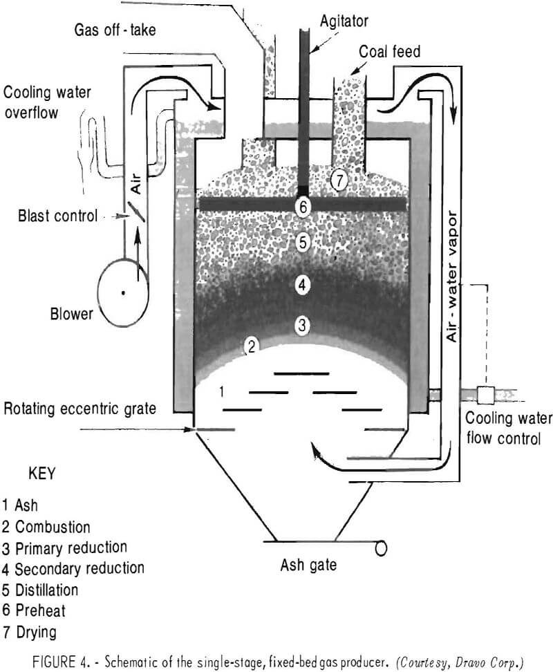
in the producer cooling jacket before the air enters at the bottom. The gasification rate (coal throughput rate) is controlled by regulating the saturation air flow. Variations in coals, such as reactivity, friability, moisture, ash content, ash softening temperature, free swelling index, and size consist, can influence the rate of gasification, which is normally expressed as the coal feed rate per unit of grate area. The reaction zones in the fixed-bed unit are reasonably well defined and include drying, preheating, distillation, reduction, combustion, and ash. Temperature in the combustion zone is maintained as high as possible without clinkering of the ash. The blast saturation temperature (BST) is very important, since too low a BST can cause the ash to fuse (clinker) while too high a BST can result in a damp, sticky ash that can be difficult to discharge through the grates. Both conditions can cause an uneven ash bed that can affect gas quality. An ash depth of about 12 to 15 in is normally maintained to protect the grate from overheating and also to insure a good distribution of air through the bed. Ash is continuously ejected through spacings in the grate and removed through a valve at the bottom of the ash pit.
The hot coal gas exits at the top of the producer at temperatures ranging from 300° to 1,200° F, depending on the moisture content of the coal, depth of the coal bed, and operating load. The major fuel components in the coal gas are carbon monoxide and hydrogen with minor amounts of methane, ethylene, ethane, and higher hydrocarbons. Sulfur and nitrogen species, such as H2S, COS, SO2, CS2, NH3, and HCN, are normally present in minor (parts per million) concentrations. The raw gas can also contain appreciable amounts of tars (except in the case of coke, charcoal, and anthracite feed stocks), along with lesser amounts of entrained solids, mainly carbon, the larger particles of which are removed by a cyclone. The low-Btu gas generated from an air-blown producer has a nominal heating value of about 135 to 175 Btu/ft³.
Lignite Gasification in Fixed-Bed Producer
From December 1978 to December 1980, three separate gasification tests, ranging from 5 to 30 days, around the clock, were run with a North Dakota Indian head lignite in the gas producer. The first two tests, conducted during December 11-15, 1978, and October 1-10, 1979, provided the operating experience and information necessary to make the equipment modifications and process design changes that contributed to the successful, 30- day-around-the-clock lignite performance test conducted from October 23 to November 21, 1980.
Gasifier operation difficulties with lignite in a fixed-bed producer were anticipated because of friability, high moisture content, and low ash-softening temperature. The producer used in the Bureau’s program was originally designed to gasify coke, charcoal, anthracite, and bituminous fuels, and it was anticipated that some changes would probably have to be made to achieve successful operations with the low-rank western subbituminous and lignite coals.
In all tests minus 2-in, plus ¾-in coke was used to start off the gasifier and was run for periods long enough to stabilize the bed and heat the refractory-lined ducts to the kiln and combustion test chamber. The raw lignite was then brought in on top of the coke. During the earlier tests it became apparent that the conventional saturation control system could not provide the uniform BST necessary for stable lignite operations. Heat generated in the retort section of the producer failed to heat the water in the jacket enough to saturate the blast air sufficiently to prevent fusion of the low-softening-temperature lignite ash. The lack of good BST control resulted in serious ash clinkering and limited throughput to low-load operations. The grate had to be operated at a full ash ejection speed to maintain an acceptable ash depth level in the producer. Large clinkers were detected near the top of the ash bed, and most of the grate openings were plugged with ash. Furthermore, the high reactivity of the lignite fuel resulted in greater throughput and necessitated operating the agitator at higher speeds to distribute the lignite to the walls and maintain a level fuel bed. Operating at the higher speeds, however, resulted in breaking of the friable lignite and the generation of fines. This was evidenced by a higher dust loading in the cyclone discharge. Also, because of the high moisture content of the lignite, the gas off-take temperature was considerably lower than that obtained from high-rank coals, resulting in tar and oil condensation in the gas ducting to the kiln and combustion test chamber.
These initial trials did indicate, however, that the raw Indianhead lignite shows promise under fixed-bed gasification conditions, but that some modifications would have to be made to the standard producer to achieve stable operations and higher lignite gasification rates.
Modifications made prior to the start of the 30-day lignite gasification campaign included the following:
Modified Lignite Feeding Arrangement. – A cone with a 29-in-diam throat was installed within the draft arrester, which is attached to the bottom of the water jacket within the producer. By directing the two coal feed inlets into a single cone, uniform mixing (less size segregation) and even flow of raw lignite into the producer was achieved. This permitted a much slower agitator speed and reduced breakage of the friable lignite. Operating without the agitator may be an eventual possibility.
Auxiliary Air-Steam Saturation Control. – The conventional BST control scheme was abandoned. Instead, air saturation was controlled automatically by injecting steam directly into the combustion air at several different locations. In this mode the existing water jacket was allowed to overflow excessively. With the new control scheme, the BST could be maintained at any desired level and within ±1° F. Steam was provided by a natural-gas-fired, packaged generator.
Pressurized Pokehole Covers. – The original sliding pokehole covers were replaced with steam-purged pressure-tight covers to prevent producer gas escape when the poke bars are inserted into the fuel bed for fire test measurements.
Ash Grate Control. A variable-speed drive was installed on the ash grate to allow better control of the ash level. The grate spacings were also increased to 6 in to accommodate the greater generation of lignite ash.
Tar Traps in Gas Ducting. – Drain valves were installed in the ducting to prevent tar and oil condensate buildup at low points in gas distribution mains to the pelletizing kiln and combustion test chamber burners. Steam injection nozzles were also located at all valves and drains to alleviate sticking and clogging with lignite tar.
Summary of 30-Day Gasification Test with Indianhead Lignite
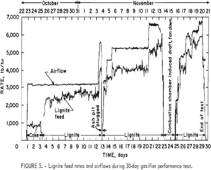
The gasifier was started up on coke October 23, 1980, with a set-point air-flow of 700 ft³/min (-3,200 lb air/hr), giving a coke gasification rate of 900 lb/hr. During this initial coke gasification phase, which lasted about 80 hours, a BST of 142° F, a coke gas exit temperature of 626° F (maximum), and a bed pressure differential of 3 in wc were maintained. On October 26, the Indianhead lignite (minus 2, plus ¾ in) was loaded into the hopper. The airflow rate was maintained at 700 ft³/min, and the lignite gasification rate immediately increased to 2,400 lb/hr and the gas off-take temperature decreased and leveled off at about 280° F. The BST was increased to 147° F and maintained within ±1° F to prevent ash clinkering. During the test period, several days of operation were conducted at feed rates of 2,400, 4,000, and 5,000 lb of lignite per hour. Lignite and airflow rates for the entire 30-day around-the-clock test are presented in figure 5. At a throughput approaching 6,000 lb/hr, the onset of gasifier instability was observed. This was evidenced by (a) erratic pressure fluctuations in the bed, (b) an increase in carbon carryover in the ash, (c) a noticeable increase of dust carryover in the cyclone collector, and (d) an increase in the CO2 content of the gas. Maintaining the desired ash level on the grate was also becoming more difficult, and since the grate was already operating at maximum capacity, the ash rejection rate could not be increased. While the gasifier remained manageable at this high rate, the heat output of approximately 38 million Btu/hr exceeded the design capacity of the downstream combustion test chamber and gas scrubber. Operation at this rate was terminated after 12 hr when the combustion chamber exhaust duct and scrubber inlet became overheated. During the 30-day run there was an interruption of the gasifier operation for 5 hr on November 4 when the ash pit plugged and ash filled to such a high level that the grate drive was stopped. On November 14 the large induced-draft fan on the combustion chamber became unbalanced, and the plant had to be shut down for approximately 40 hours until it could be rebalanced. There also occurred a 45-min local power failure and two momentary power failures during the test when gasifier shutdown was not anticipated. In the last three instances the safety controls “failed” safe, and the raw lignite gas was vented through the 10-in stack and incinerated with the afterburner.
Lignite performance data generated from November 6 through 12 at a raw lignite feed rate slightly in excess of 2 tons/hr are presented in tables 1 through 8. Although this rate is somewhat below the capability of this producer to gasify the Indianhead lignite,
the data do represent a long term (140 hr) of uninterrupted, stable operation at a level closely approaching “maximum” capacity.
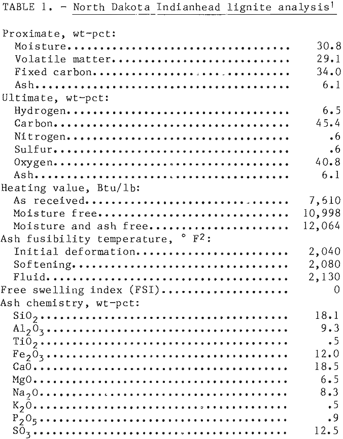
An analysis of the raw Indianhead lignite for the test period is provided in table 1. As noted, the ash has a softening temperature below 2,100° F and contains a much higher concentration of alkali metal and alkali earth compounds than the high-rank eastern coals. Lignite also has a very high moisture content and was expected to produce a much lower exit gas temperature than would be obtained with anthracite or bituminous coals.
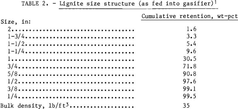
The size of the lignite feed (table 2) indicates that 72 pct was above ¾-in and 98 pct over ½-in. As noted previously, the lignite was screened at ¾-in just before it was transported to the gasifier storage bin by a bucket elevator. Most of the breakage to the minus ¾-in, plus ¼-in size fraction resulted from this harsh conveying treatment. It is also worth noting that the degradation of Indianhead lignite, stored on the site for over 2 years, was limited to the top few inches of the pile.
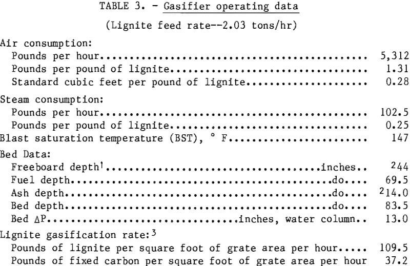
Gasifier operating conditions at the 2-ton/hr rate are given in table 3. The gas producer was very stable over the entire test period, and variations from the average values reported here were minimal. The BST temperature was easily controlled with the new steam injection system and was maintained at 147° F to prevent ash clinkering. The pressure drop of 13 in wc across the 7-ft bed (fuel plus ash) did not fluctuate more than ±1 inch wc, which indicated that steady state conditions had been achieved. Air and steam consumption were 1.3 and 0.25 lb per pound of raw lignite, respectively. providing a lignite gasification rate of 110 lb per square foot of grate area per hour, or about 40 lb/ft² per hour less than the projected maximum capacity for this unit.
Accurate measurements of the ash depth (distance from top of the grate to the hot zone) proved to be more difficult with lignite than with coke or bituminous coal. Fire bed checks on the ash with these latter fuels normally produce a clear-cut visual (bright) incandenscent zone. With lignite, however even after leaving the bars in the fire zone for 7 to 8 min (twice as long as normal) no sharp incandescent zone was observed, indicating a lower combustion zone temperature.
Temperature and pressure profiles of the fuel bed were obtained at the 2-tons of lignite per hour rate (fig. 6). A temperature probe containing six thermocouples spaced 9 in apart was inserted through one of the pokeholes into the bed. A gas pressure profile was also obtained in a similar manner using a static pressure probe. The temperature profile indicated a narrow combustion zone with a maximum temperature of 1,900° to 1.950° F a gasification zone of about 1,200° to 1,400° F, and a drying- devolatization zone ranging from 200° to 1,200° F. The pressure profile showed a linear increase in pressure all the way to the bottom of the bed, ranging from
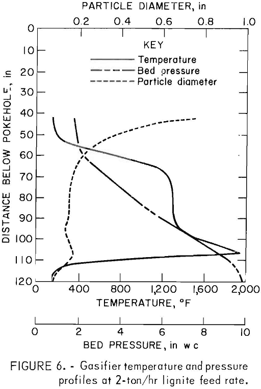
2 in wc at the bed surface to about 10 in wc at the grate. Using measured gas flow, temperature, and pressure profile data, the mean lignite particle size was calculated using a standard equation for pressure drop across a packed bed. As seen in figure 6, the mean particle diameter rapidly decreased from ¾ in at the surface to about 1/8 in after descending less than 2 ft below the surface. This size breakdown was verified at the conclusion of the test run when the fuel bed was dumped and found to contain ¼- to 1/8-in-diam lignite particles. The rapid drying of the lignite appears to be the driving mechanism for the size degradation.
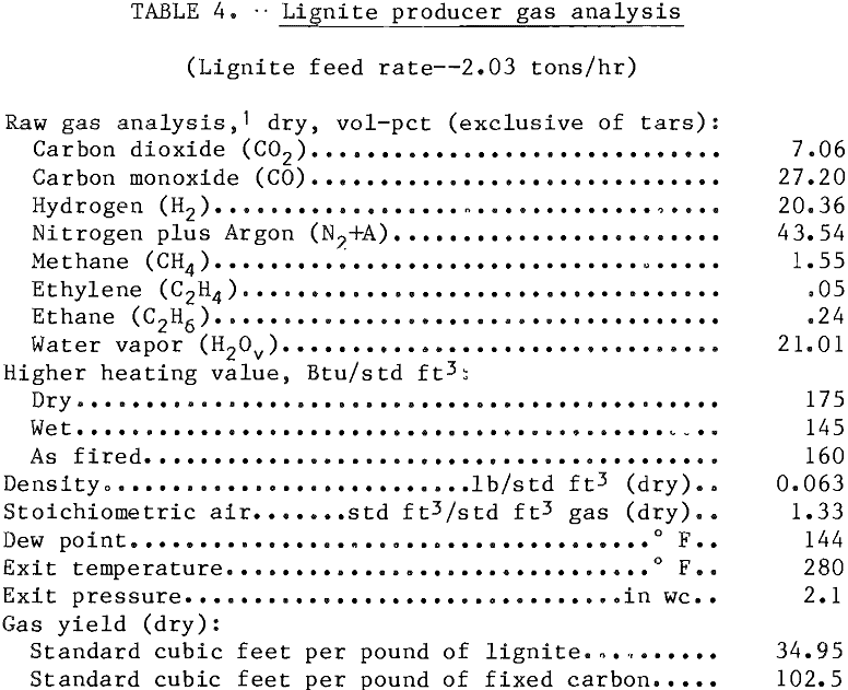
Lignite gas of consistently high quality, that is 175 Btu/std ft³ (dry) and 160 Btu/std ft³ (as fired), was generated during the test period (table 4). The moisture content of the raw gas averaged about 21 pct. Since the temperature of the gas exiting from the producer (280° F) was normally above the gas dew-point (144° F), most of the water vapor was retained in the gas, resulting in a somewhat lower Btu gas to the downstream burner systems. Gas quality was not sensitive to variation in load or operating conditions. A gas yield of 35 std ft³/lb lignite was obtained. Early studies conducted at the Bureau’s Twin Cities (Minn,) facility indicated that although the gas yield per pound of fuel increases with increased fixed-carbon content both the gas yield and gasification rate per pound of fixed carbon remain essentially constant.
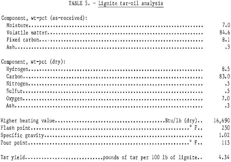
Condensation of lignite tars and oils in the downstream ducting, particularly at the horizontal and elbow sections, control valves, and gas flow elements, remains a significant problem despite installation of tar traps at low points in the system. The low lignite exit gas temperature was approaching or at times somewhat below the tar-oil condensate dewpoint. The lignite tar-oil in the vapor phase begins to condense out when the gas temperature drops below about 260° F. Table 5 contains an analysis of tar samples collected with a wet Venturi scrubber during the test program. The tar had a heating value of 16,690 Btu/lb (dry), which is somewhat less than that of No. 6 fuel oil— 18,300 Btu/lb. The concentration of tar in the lignite gas is estimated to be about 4 to 4.5 pct of the lignite feed.
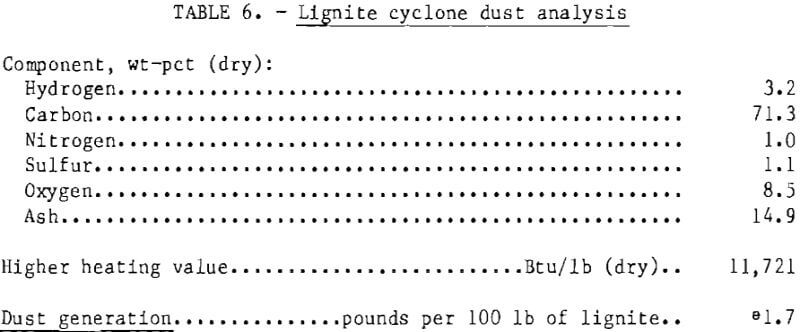
Dust removed from the cyclone dust catcher (table 6) was composed mainly of lignite fines and/or char along with entrained tars. This high-carbon material had a heating value closely resembling that of moisture-free lignite. The true size structure of the material was difficult to determine since it tended to agglomerate in the cyclone.
As expected, the gasifier bottom ash (table 7) closely resembled the lignite feed ash in composition. Carbon carryover in the ash was very low (1 to 1.5 pct) and remained so up to a lignite feed rate of 2.5 tons/hr. Above this level the ash began to take on a noticeably blackish hue, an indication of an increase in carbon content. Carbon analysis of the ash at 3-ton/hr rate was above 14 pct, indicating insufficient residence time to gasify all the lignite.
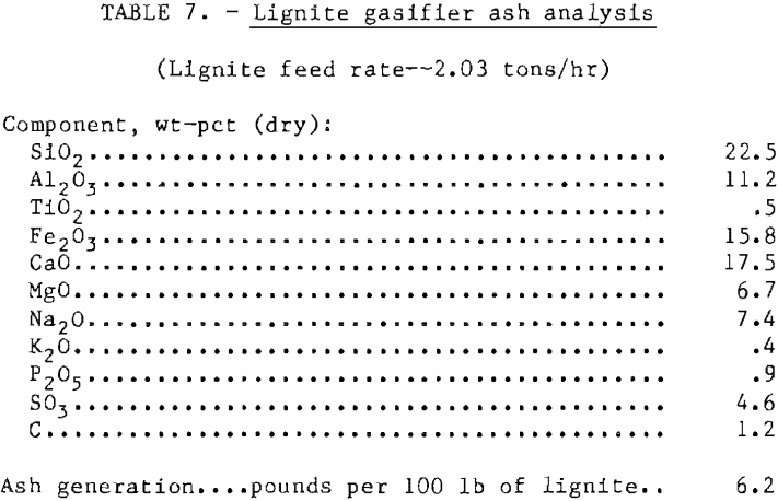
A source test and evaluation (STE) performed during the earlier December 9-15, 1978, North Dakota Indianhead lignite gasification test by the Radian Corporation under EPA contract showed that the two solid wastes (gasifier ash and cyclone dust) generated by operation with Indianhead lignite would be classified as nonhazardous according to the Resource Conservation and Recovery Act (RCRA) guidelines. In addition, neither solid waste exhibited a detectable biological response in any of the bioassay tests performed. The waste water streams (ash sluice and cyclone dust quench water) exceeded the national drinking water standards for pH, TDS, and certain elemental components, and treatment of the streams prior to discharge would be required.
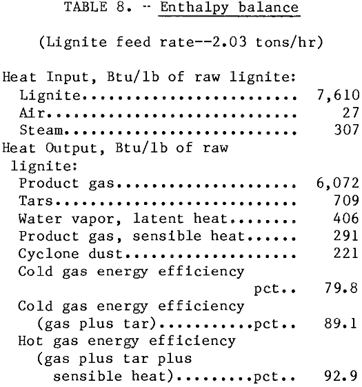
An enthalpy balance at the 2-ton/hr lignite gasification rate is given in table 8. For a system where the gas is cooled and sensible heat and tars and oils are removed, the resulting cold gas efficiency is 79.8 pct. If the tars and oils can be removed and used as fuel, the cold gas efficiency increases to 89.1 pct. For a raw, hot gas installation in which the product gas is combusted directly, the gasifier converts 92.9 pct of the energy input into product gas. Although the maximum feed rate achieved was nearly 3 tons/hr, the “reasonable maximum” appears to be closer to 2.5 tons/hr, a gasification rate of about 150 lb of lignite per square foot of grate area per hour. This projects to a lignite gasification rate approaching 6 tons/hr (~72 million Btu/ hr) in the 10-ft-diam Galusha gas producer, the largest presently built.
Pellet Induration with Raw Low-Btu Lignite Gas
A commercial hematite-martite- hydrous oxide concentrate obtained from a beneficiation plant in Michigan’s Upper Peninsula was used in the pellet induration studies. Hematite concentrates require a higher temperature and more heat per ton of product to indurate than magnetite concentrates—1.2 to 1.5 mil¬lion Btu/lt versus 0.5 to 0.7 million Btu/lt—and matching hematite with the raw lignite gas was considered the worst case situation.
The filter cake concentrate was formed into pellets in the balling disk previously described, employing practices closely simulating those of the industry. A bentonite addition of about 18.5 lb/lt was added to the concentrate. Following thorough mixing, the green balls were formed with the addition of the required amount of water, sized at minus ½ in, plus 3/8 in, and conveyed to the grate preheater at a rate of about 940 lb/hr. Drying and preheating (partial hardening) were accomplished with an above the grate temperature of 650° to 700° C (1,202° to 1,292° F) in the downdraft preheat windbox and 250° to 275° C (482° to 527° F) in the updraft drying windbox.
The pilot plant rotary kiln normally requires a heat input of 3.0 to 3.5 million Btu/hr to maintain a maximum induration temperature of 1,300° C (2,372° F) and a kiln exit gas temperature of about 900° C (1,652° F) when firing with a natural gas premix burner. At pellet feed rates employed in these experiments, this is equivalent to about 9 million Btu per long ton of pellets. This high heat consumption results because of the high heat losses associated with a small rotary kiln. Because this degree of consumption is inordinately high, realistic values for the thermal requirements to indurate hematite pellets with raw lignite gas could not be obtained.
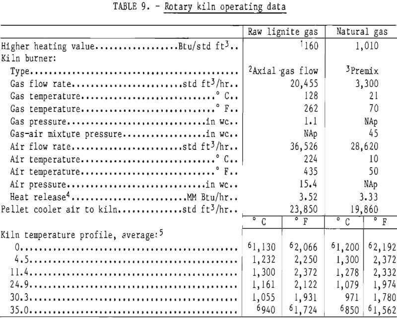
Rotary kiln operating conditions maintained during hematite pelletization with 100-pct raw lignite gas are summarized in table 9. Corresponding data for hematite pelletization with 100-pct natural gas firing are not available; however, operating conditions for natural gas firing of magnetite pellets are presented in table 9 for comparison. A raw lignite gas flow of 20,455 std ft³/hr (3.5 million Btu/hr) was necessary to achieve the 1,300° C (2,372° F) temperature required for pellet induration. The raw gas had a higher heating value, as fired, of about 160 Btu/std ft³. The gas flame was very stable at this firing rate and provided a temperature profile suitable for pelletizing in the small kiln. Unfortunately, because the producer gas burner was physically too large to permit visual observation of the kiln interior during the pelletizing operations, estimations as to the actual flame configuration, that is, length-to-diameter ratio, were not made.
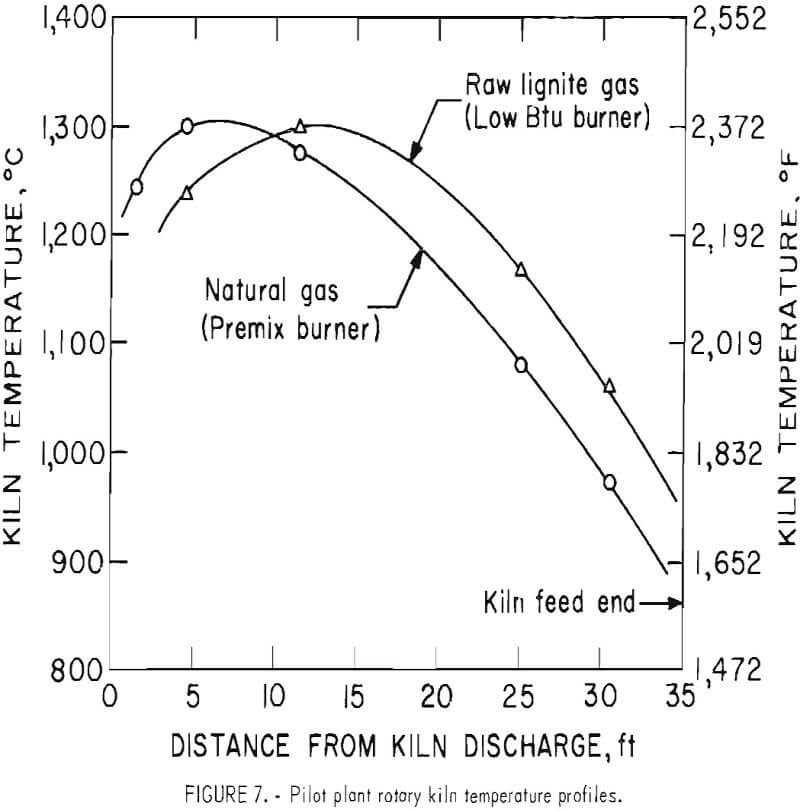
A comparison of the kiln temperature profiles produced with the raw lignite gas burner and a natural gas premix burner is shown graphically in figure 7. The maximum kiln temperature obtained with the raw lignite gas occurred about 11½ to 12 ft from the kiln discharge end, compared with 4½ to 5 ft for the natural gas. At the feed end of the kiln the temperature with lignite gas was about 90° C (194° F) higher than with the natural gas. The longer flame obtained with the raw lignite gas is probably due to the difference in burner designs although the presence of entrained tars and oils in the raw gas may be a contributing factor.
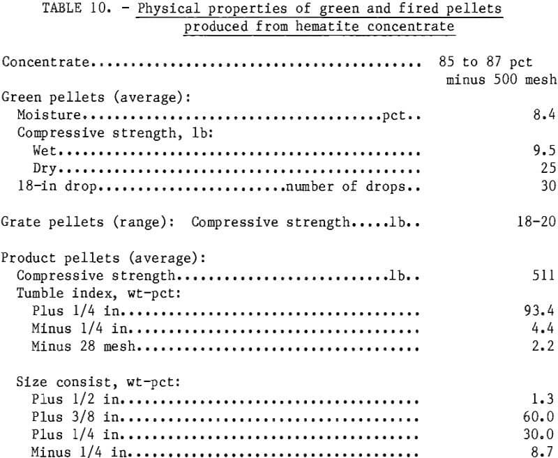
Maintaining good control of the maximum pelletizing temperature was difficult at times because of the slow response of the automatic temperature control system to compensate for fluctuations in gas flow to the kiln. During the initial phase of the pelletizing test, pellet quality was quite high; however, as the test progressed it fell below commercial acceptance, with crushing strengths decreasing to 275 lb and the tumble index to 75 pct plus ¼ in. During this period, the kiln temperature had crept up to a high of 1,360° C (2,480° F) [1,340° C (2,444° F) average]. Analyses of the product pellets showed an increase in ferrous iron from 0.2 pct to a high of 5.5 pct (4.5-pct average). This indicated that the pellets had been “overfired,” which evidently accounted for their low strengths. Temperatures in the kiln were subsequently reduced to 1,300° C, (2,372° F) and pellet quality began to increase again to commercially acceptable levels with strengths in excess of 500 lb and 90 to 95 pct plus
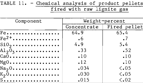
¼ in after tumble (table 10). Chemical analysis of the fired pellets (table 11) showed no noticeable contamination from the raw lignite gas combustion products. Neither was there any detectable sign of kiln ringing or buildup in the grate-to-kiln transfer section as was the case with direct-coal-firing tests conducted in the same kiln with similar low-rank coals.
Conclusions
North Dakota Indianhead lignite was found to be a reactive fuel to gasify in a standard airblown single-stage fixed- bed gas producer. A maximum stable gasification rate of 150 lb per square foot of grate area per hour was attained with minus 2-in, plus ¾-in feed stock in the 6.5-ft-diam unit. This high gasification rate compared with that normally reported for bituminous coal (90 lb/ft³· hr-¹) and anthracite (30 lb/ft³· hr-¹) is indicative of the high reactivity of the North Dakota lignites. The lignite gas was of consistently high quality (=175 Btu/std ft³ [dry]) and was not noticeably affected by variations in load or operating conditions. Interfacing of the gas producer with the pelletizing kiln appears to be both feasible and practical, although efforts will have to be made to prevent the tar and oils in the raw lignite gas from condensing out and depositing on critical control valves and in the downstream ducting system. Adequate kiln temperatures were generated in the pilot plant rotary kiln with the raw lignite gas, and commercially accept¬able quality hematite pellets were produced.
The most efficient application of this type of gasifier for a grate-kiln or straight-grate pelletizing system would undoubtedly be an onsite installation close to the pelletizing furnace to deliver a hot, raw gas directly to the burner, thereby retaining the sensible heat in the gas and minimizing tar condensation. For a shaft pelletizing application, the gas would have to be pressurized, and because of the more complicated distribution system, detarring and oil elimination would be required.
