Table of Contents
Cyprus Pima has two concentrators, one with a conventional crushing-grinding circuit and the other using semiautogenous grinding followed by ball mills.
Old Mill Flowsheet
The original mill was constructed in 1956 but has been expanded three times so that by 1967 there were ten sections having a total capacity of 36,000 tpd. Subsequent revisions have increased this capacity to about 40,000 tpd. Mine ore is fed to a conventional three-stage crushing plant with final product, averaging about 25% – ½ inch, being conveyed to fine ore bins
New Mill Flowsheet
A completely new and separate primary crusher was constructed for the new mill which was put on stream late in 1971. Present capacity of the new mill is about 19,000 tpd. The new primary is identical with the existing one except that the crusher discharge is fed to a Barber-Greene radial stacker conveyor that can serve both the old mill stockpile and the new mill stockpile.
One unique feature of the grinding circuit is a provision to use the cyclone feed sump as a sump common to both ball mills or as individual sumps to allow the ball mill circuits to be operated separately. Another advantage is that when one semiautogenous mill is down for repair, both ball mills can be used to grind more tonnage than if only one ball mill circuit were available.
Instrumentation as originally designed included a horsepower control loop for the semiautogenous mill circuit which utilized sensors to measure mass flow (magnetic flow meters and density gauges). The control loop depended on accurate measurements for proper operation, but the errors introduced by these two sensors were greater than the variable being sensed for control purposes.
The objective at Pima has been to grind maximum tonnage while striving to keep recoveries within reasonable limits and stabilize the circuit as much as possible. The primary grind is kept at 20-25% +65 mesh (about 50-55% -200 mesh) with flotation feed solids at 40-45%. These conditions give a recovery of 84-86% copper and result in the best economics. A much finer grind is required to yield a significant increase in recovery.
Metallurgical engineers who have considerable operating experience, who have a good instrumentation background and who have an excellent knowledge of the capabilities and limitations of process control computers are not the easiest men in the world to find or to keep. Cyprus Pima had two such men in the late sixties and early seventies and lost them both before an instrumentation team could be developed.
The original analog grinding circuit control used an ore-water ratio controller and an analog loop for controlling new feed tonnage. The optim loop detected a change in the semiautogenous mill by comparing input and output tonnages and then c the new feed, within horsepower constraints, to i inventory constant. Inputs were measured by bell the output, the mass flow of screen undersize, was by a magnetic flow meter and a nuclear density gave mill solids inventory is about 40 tons at any instant input-output of 200 to 1200 tph (depending on ore).
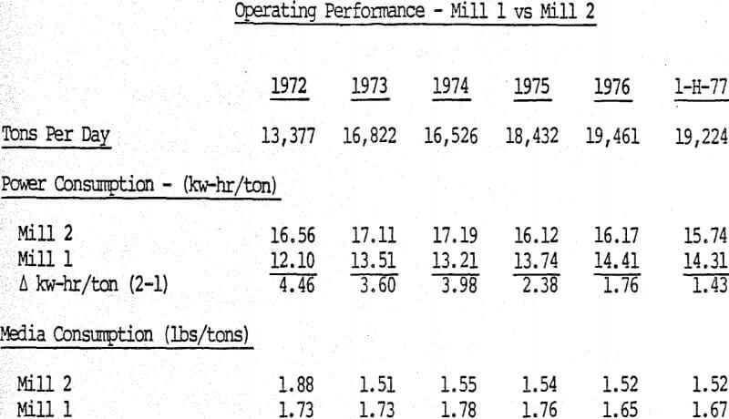
Mill 2 was designed for 14,000 tpd and during the first year of operation, 1972, throughput averaged 13,377 tpd. However, during the last quarter of 1972 the grinding rate averaged 16,648 tpd on a daily basis. The digital control system was installed in October 1974. Results tabulated below show how performance was improved.

Duval Grinding Circuit Control
Duval Corporation is implementing computer control of its single-stage ball mill grinding operation in the Sierrita mill using a hierarchical approach. The mill is split into two sections of eight mills, each with a PDP 11/34 satellite computer operating under Decnet, being used for the first level of control in each section. The host computer, a PDP 11/40, is located in Tucson, approximately forty miles from the mill site. The grinding system operator interfaces directly with the satellite computers, located immediately below the control room, via three color cathode ray tubes (CRT’s) located in an operator’s console which permits viewing all three CRT’s from a central vantage point.
The second phase involves a systematic study of the psuedo steady state response of the milling circuit in order to define an optimum operating strategy to be pursued as ore characteristics or availability change. An early objective of this study is to develop an approximate relationship between a particle size criterion in the product material and both measured and derived variables. As sufficient data becomes available it is expected that process optimization will be based more directly upon a correlation of recovery with, process variables and ore type.
A Review of Automated Grinding Control Systems
The original grinding control concept was based on the loose relationship between percent solids and the degree of grind. This and other control schemes are discussed.
Variables that have been employed in the different strategies are feed rate, head water addition, dilution water make-up, percent solids in cyclone feed, ball mill motor power draw, cyclone feed sump level and particle size measurement.

Grinding Circuit Description
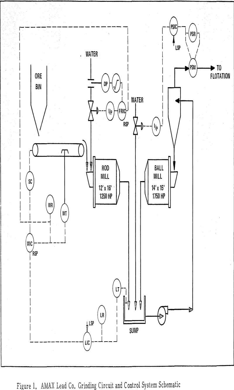
In the Buick grinding circuit, ore is fed by four 36″ belt feeders, paired two to each 3000 ton ore bin. Each pair of feeders consists of one manually controlled feeder and one automatically controlled feeder. Ore from the feeders discharges to a 24″ collecting belt which discharges to another 24″ belt feeding the rod mill.
The primary control system design objectives are:
- To maintain a constant and preselected size of grind in the final product of the grinding circuit.
- To continuously maintain circuit throughput at the maximum practicable value, so as to keep the unit grinding costs to a minimum.
The feed control loop matches the actual rod mill feed as indicated by the Ramsey belt scale with the controller setpoint which is obtained from the sump level detector. This loop is useful in reducing throughput disturbances resulting from blocked chutes or other feed malfunctions. The head water control loop maintains a constant preset ratio between rod mill feed rate and rod mill water addition so that a constant slurry density is maintained within the rod mill.


