Table of Contents
Gypsum and its products are economical materials in their respective fields. Lime and hydraulic cement plasters compete to a limited extent with gypsum in the plaster field. Lime is used today in construction, chiefly as an ingredient in the finish coat over gypsum-plaster base coats.
Gypsum plaster is mixed with water and aggregates, such as sand, expanded perlite, or exfoliated vermiculite, in certain proportions and applied, usually in two or three coats, as an inside finish over gypsum lath, wood lath, metal lath, monolithic concrete or concrete blocks, or other backing. Portland-cement plaster is used chiefly as an exterior stucco, in locations unavoidably affected by dampness or where subjection to abrasion precludes the use of gypsum plaster.
As a retarder in cement, no other material compares with gypsum for combined economy and effectiveness. Some current experiments on the use of gypsum retarders indicate that a considerably higher gypsum content might help make concrete more lasting.
Agricultural gypsum is used to offset alkali and to restore impervious, dispersed soils that have been deflocculated by overdoses of ammonia-rich fertilizers or by soda in irrigation water. Ground gypsum and anhydrite are used in Southern States as soil conditioners for leguminous crops. Agricultural gypsum competes with a variety of natural and manufactured materials; its cheapness in areas surrounding gypsum deposits makes it a preferred soil additive.
Gypsum and anhydrite, particularly the latter, may be converted to ammonium sulfate fertilizer by processing with coke and ammonia.
Calcined gypsum is also used for the following industrial plasters: Terra cotta, pottery, molding, orthopedic and dental, and statuary and in the plate-glass industry. Miscellaneous uses for pure white uncalcined gypsum are terra alba, which is used as a filler in paper and paints and as a nutrient in growing yeast. Off-white uncalcined gypsum is used as a filler in various products or as an insecticide carrier.
This report is one of a series published by the Bureau of Mines on mining methods, performance, and costs of mining operations in the United States. The primary purpose of these papers is to promote the development and conservation of our mineral resources by disseminating technologic information on methods, practices, and results that may be applied to the engineering analysis and solution of mining problems.
Gypsum mining in Iowa has been confined to two localities: One, in Webster County in the immediate vicinity of Fort Dodge, is slightly north and west of the center of the State; the other is at Centerville in Appanoose County in the southeastern part of the State (fig. 1).
All currently active mines and plants in Iowa are in the Fort Dodge area. The Centerville mine was worked intermittently from 1912 to 1934. The 4-foot-thick bed of gypsum, 550 feet below the surface, changes to anhydrite at the limits of the workings.
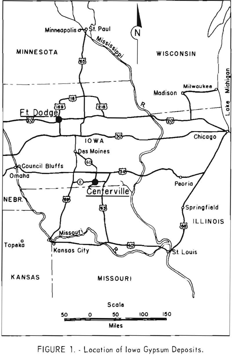
Geographically, Fort Dodge is well situated for distributing gypsum products to industrially important markets within the State and to distribution points in the surrounding States. Fort Dodge is served by four rail-roads (the Illinois-Central, Chicago and Great Western, Minneapolis & St. Louis, and the Fort Dodge, Des Moines & Southern) and is also at the junction of two major highways (U.S. 169 and U.S. 20).
The first known record of the presence of gypsum in Iowa appeared in 1852. Discovery of the deposit was credited to David Dale Owen, who noted the gypsum outcrops along the bluffs of the Des Moines River near Fort Dodge in 1849. Apparently no work was done in the district until 1858, when geologic studies were undertaken. Records are extremely vague as to the date of the start of actual mining operations. The first gypsum mill was constructed in 1872, 2 miles southeast of Fort Dodge.
From the beginning of gypsum mining in the Fort Dodge area until about 1895 most mines and quarries were situated along the banks of the Des Moines River and Its tributaries. Accessibility to the outcrops and the depth of tho overburden were two principal factors in selecting the site for mining operations.
Although the gypsum deposit was known to extend over a large area in the prairie adjoining the site of the early operations along the river, very little exploration was done until 1892. At this time the Cardiff Gypsum Co. sank the first shaft in the virgin area and began underground mining operations. Other companies were not long in starting similar operations, and soon almost the entire output of gypsum from the district was being mined from the newly developed area.
The mining method using room-and-pillar stoping, was comparable in all mines, except for minor variations to meet local conditions.
The shaft site usually was chosen so that the crude gypsum could be delivered to the mill with minimum handling. Shafts were sunk to the desired depth, sometimes a few feet below the bottom of the gypsum bed or to the elevation at which the entry was to be driven.
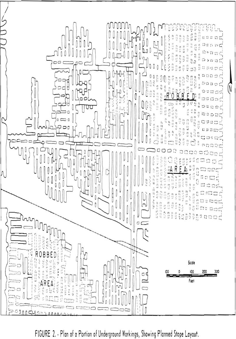
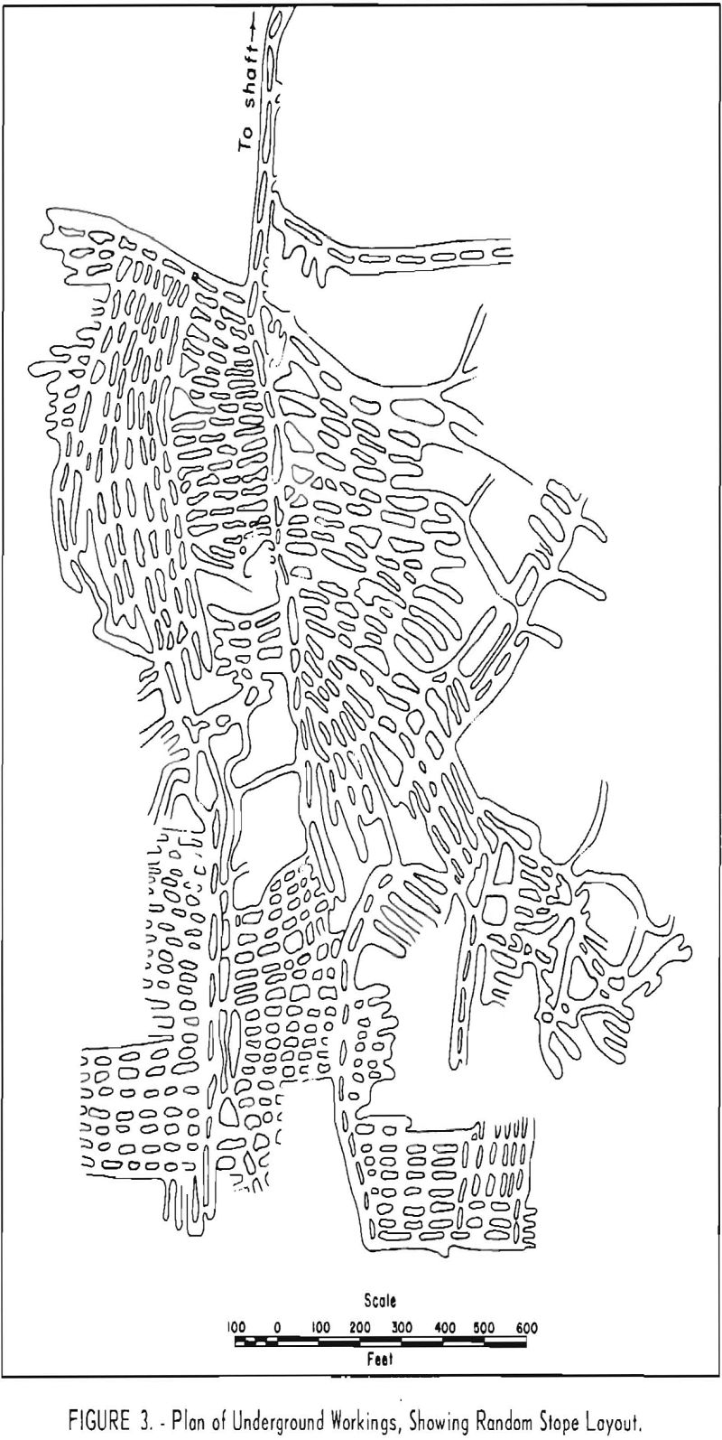
The area to be mined ordinarily was divided into panels of uniform size with cross entries, rooms, and pillars spaced at regular intervals (fig. 2). The sizes of the rooms and pillars were kept as uniform as possible. In a few mines, however, the layout plan was quite irregular, with no definite system, although some effort was made to space rooms and pillars evenly and to have some regularity in their size and shape (fig. 3).
The main development and haulageway consisted of two parallel 9- by 15- foot drifts separated by pillars 15 feet in width and of varying length. Rooms 20 feet wide were driven laterally from the development drift for 200 feet or more. Rooms were separated by pillars 15 feet in width.
The height of the rooms depended upon the thickness of the gypsum and overburden but usually was 9 feet, leaving 2 to 4 feet of gypsum in the floor and 5 to 6 feet in the roof. Pillars and roof were trimmed on retreating from an area, except where subsidence of the surface was a consideration; in this instance only the pillars were trimmed. The bottom was not taken up in retreating from a mined-out area. Beneath permanent structures, or highway and railroad rights-of-way, no openings were driven other than development openings.
This method of mining remained unchanged until 1927, when the largest producer in the district began stripping and quarrying, demonstrating that a considerable saving in operating costs could be made, even with an overburden- gypsum ratio of 3-½:1. Also, recovery of approximately 98 percent of the gypsum, as compared with only 40 to 45 percent by underground methods, was another factor in favor of stripping and quarrying methods. Although lower operating costs and higher recovery were primary factors governing the change to surface mining methods, another contributing factor was the type of earth-moving equipment that was being developed at that time. Greater capacity, higher speeds with greater loads, and increased durability of this equipment made it possible to remove a greater depth of overburden at lower costs than formerly. However, for various reasons some companies in the district were slow to adopt surface mining methods, and it was not until 1945 that some of the other producers began to strip and quarry the deposit.
The United States Gypsum Co. was organized in 1901 and began operations in 1902. It took over seven small plants with wooden buildings, two of which
burned later. The others were dismantled alter the company built a large, modern, fireproof plant, which, in later years, was expanded further to become the largest in the district. In 1918 six companies were operating mines and plants in the Fort Dodge area. Today, alter consolidation of some of their mineral holdings, four of the six are still operating. These tour are: The Bestwall Gypsum Co., the National Gypsum Co., the United States Gypsum Co., and the Celotex Corp. At the time of writing, the Cidotex Corp. was in the process of expanding, and the company operations had not been developed to the point where it was feasible to include descriptive data on their activities.
Description of Deposits
The formation of gypsum in commercial quantities can generally be ascribed to one of three causes: Transformation of deposits, generally limestone, by chemical reactions involving weak solutions of sulfuric acid; precipitation from sea water, due primarily to concentration by evaporation; or reactions between the salts in solution.
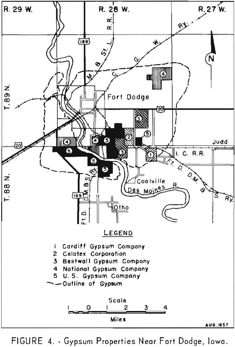
Although several theories have been proposed, the Fort Dodge deposits are generally accepted as being of aqueous origin. Some believe that the basin containing the deposit was inundated by an ancient sea containing the calcium sulfates and carbonates and the sodium, magnesium, and potassium chlorides besides other salts common to sea water. Due to emergence and submergence, or to existence of a natural barrier, the embayment thereafter received only periodic supplies of sea water. This condition allowed considerable evaporation approximately 80 percent increasing the concentration of the calcium sulfate component, per unit of water, which resulted in subsequent deposition of the gypsum beds. Under normal conditions limestone would be deposited before the gypsum. In the subject area, however, the gypsum beds lie unconformably on limestone and clayey shale members of the Upper Carboniferous, indicating a break in the natural sequence of deposition. The assumption is that reactions took place between the salts trapped in the embayment eliminating the calcium carbonate content as such and either converting it to gypsum or to a salt that is more soluble, allowing the gypsum to precipitate in a nearly pure form. Figure 4 shows the location of the Fort Dodge gypsum deposit and its approximate lateral extent.
The deposit, which occurs in an oval basin, has a northeast-southwest axis. This basin is roughly rectangular and 6.5 miles in an east-west direction by 5.5 miles from north to south. This site lies wholly within Webster County and is confined to the immediate vicinity of Fort Dodge.
Several square miles of this area have been cut away by the Des Moines River and tributary streams; and, although various estimates of the remaining area of the deposit, some as high as 70 square miles, have been made, the outline as illustrated in figure 4 is an average of these estimates and thought to be generally accurate.
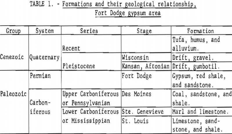
Stratigraphy in the Fort Dodge region is shown in table 1.
The table is based on information obtained from such sources as surface exposures along the Des Moines River, Soldier, Lizard, and Two Mile Creeks; well logs; drill holes; and underground workings of the gypsum mines.
Only very small amounts of impurities are found in the deposit, and these consist principally of clay and sand in the very thin seams along bedding planes of the gypsum. The gypsum is of exceptionally good quality. No anhydrite occurs in the deposit, except in one small area.
Thickness of the gypsum ranges from 2 to 30 feet, depending upon the extent of erosion. Average thickness is about 20 feet. The deposit is nearly horizontal and is made up of thin strata called “flags” that range from 2 inches to 2 feet in thickness.
The overburden consists of varying thicknesses of gumbotil, glacial drift, sand, gravel, and alluvium. The total depth ranges from 30 to 85 feet, averaging 55 feet.
Prior to glaciation, the surface of the deposit was exposed to the action of streams, runoff, and weathering until portions reached the stage of mature dissection. This unevenness of the top of the deposit causes some difficulty, particularly in drilling and stripping.
Mining Methods
Quarrying – General
Plans for stripping and quarrying In the Fort Dodge area are based largely on such factors as the depth and composition of the overburden and the thickness and attitude of the gypsum deposit. Generally these conditions are relatively constant throughout the greater part of the area, therefore, the general layout of the various stripping and quarrying operations in the district is much the same.
Usually the working areas are laid out in adjoining and parallel cuts the length or width of the property. Individual cuts range in length from 500 to 4,000 feet and in width from 100 to 150 feet.
In stripping operations bank slopes are maintained at a 1-½:1 ratio. Overburden is removed by draglines or scrapers or a combination of both. Overburden to stone ratio is about 3:1. Most of the spoil material is cast back into exhausted parts of the quarry and the remainder dumped on barren tracts. In the past 8-foot berms or retaining walls of gypsum were left between the cuts to retain the backcast material. With the advent of scraper units and the removal of a large percentage of the waste to old spoil areas, the need for means of retaining backcast material was eliminated, with a resultant increase; in the percentage of recovery of the gypsum. Present recovery is nearly 100 percent. The distance for scraper haulage ranges from 300 feet minimum to 2,000 feet maximum.
Final cleanup is accomplished with small clamshells, bulldozers, and specialized equipment, the material being cast back into the previous cut. Very little hand shovel work is done on the cleanup phase of stripping.
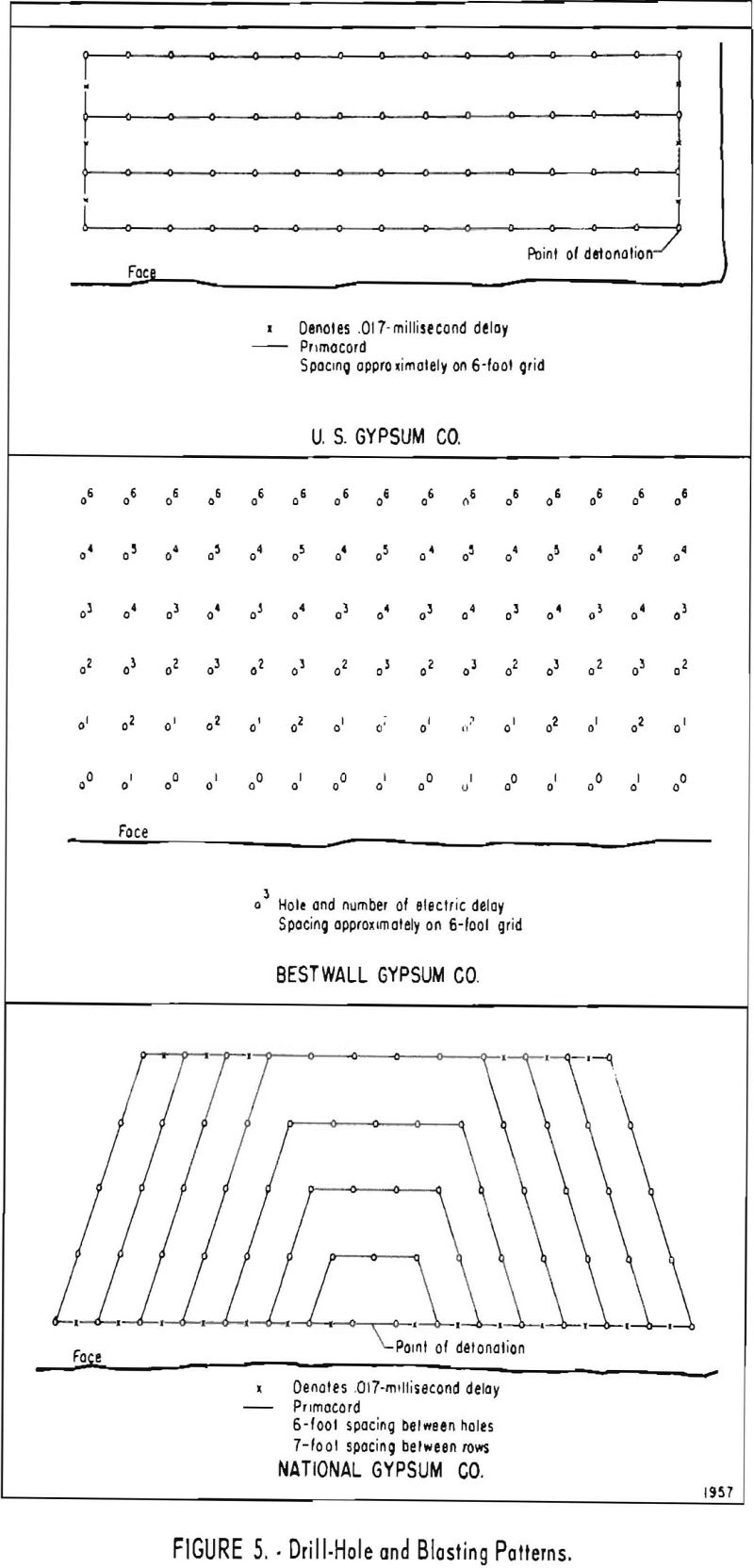
The blasthole pattern is comparable at all quarries (fig. 5). Holes are drilled in a grid pattern, with hole and row spacings of 6 and 7 feet. Holes are bottomed at 2- and 2-½-inch diameters.
The dynamite in use throughout the district is Gelex No. 5, primed with Gelex No. 2. Experimental work on the use of ammonium nitrate as an explosive agent is being conducted in the area. The present loading practice includes both single- and multiple-desk spacings of the charge. Both electric blasting caps and Primacord are used as means of detonation. Delays of either the electric or Primacord type are used in all blasting.
The broken gypsum is loaded into trucks by crawler-mounted, diesel-operated shovels. Haulage distance varies from 4,000 to 12,000 feet.
The drainage problem is similar in all operations. Water is directed by drainage ditches to strategically located sumps, where it is collected, pumped out of the quarry, and discharged into natural surface drainage features.
Maintenance of equipment in the area is of primary concern to the operating companies and all equipment is kept in excellent repair.
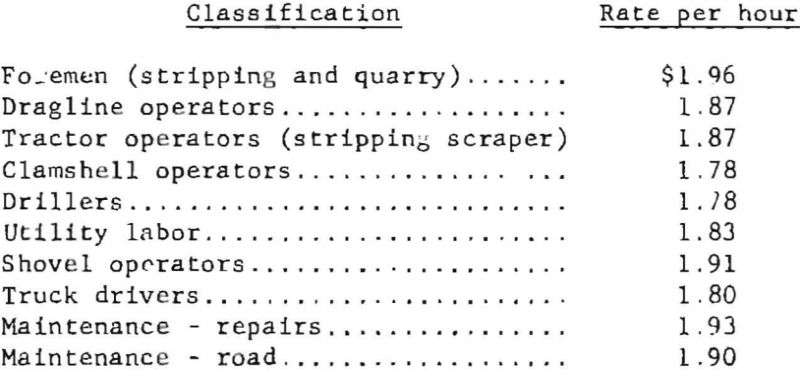
Average wage rate in the district is as follows:
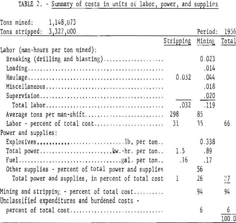
Performance data for the district as a whole are given in table 2, and cover the 1956 operations of the three major companies in the district.
Operations of Individual Properties
United States Gypsum Co.
General
The United States Gypsum Co. property consists of 749 acres, with the plant approximately 4-½ miles southeast of Fort Dodge. The company has been operating in the district since 1902 and Is the largest producer of gypsum and gypsum products in the area.
The stone mined in the company quarries averages 96 percent gypsum. The horizon being exploited ranges from 10 to 30 feet in thickness. The depth of overburden is 50 to 100 feet.
The main company office is at 300 E Adams St., Chicago, 111. M. E. Davidson, works manager, is in charge of local operations.
Exploration
Exploration is conducted well in advance of stripping and quarrying. A staggered grid with holes on 200-foot centers is laid out on the area selected. Drilling is done with a Parmanco auger drill, using a 4-inch bit. An experienced drill operator can determine quite closely the depth below the surface and the thickness of the gypsum formation by the action of the drill. Because of the overall purity of the formation, little or no sampling is necessary. In the areas where the surface of the gypsum deposit has been subjected to a minimum amount of erosion, it is possible to estimate reserves. However, in the areas that have been subjected to intensive erosive action and where dissection in some instances is almost complete, it is extremely difficult to arrive at a dependable estimate.
Development and Mining
The center-cut system of quarrying has become standard in developing and mining the deposit. However, recent changes in the stripping methods have considerably increased the efficiency of quarrying operations. In the past the 50- to 100-foot glacial drift overlying the deposit was removed by a 5-cubic-yard Marion 360 Dragline. During stripping operations, bank slopes were maintained at a ratio of 1-½:1. The spoil usually was cast back into the previous cut. To retain this waste material, a 6- to 8-foot berm wall was left between the two cuts. Approximately 18 inches of gypsum was left in the bottom of each cut to provide a firm roadway for transportation of rock and equipment.
Cleaning operations consisted of following the 5-cubic-yard dragline and hand cleaning with shovels and brooms.
As the rate of production was increased to meet demands, it became apparent that the stripping rate would have to be increased. Two Caterpillar crawler tractors, a D7 and a D8, were purchased in 1948 and put into operation, dozing the cut ahead of the dragline. A D8 tractor and a Caterpillar 80 tractor-drawn scraper were added in 1950.
Before October 1955 production came entirely from what is now known as the East quarry. To increase production, the west face of the deposit was opened, approximately 3,000 feet west of the East quarry face, This company purchased, for stripping purposes, three Caterpillar DW21 tractors with No. 21 scrapers, two D8 tractors, and a 212 Motorgrader.
The area between the East and the West quarries consists of stripping material cast back as the east face was advanced. Overburden in the area of the West quarry ranges from 60 to 100 feet in depth. To handle the additional stripping, another Caterpillar D21 unit with a 470 scraper was added to the scraper fleet. Overall stripping ratio of waste to rock is 3:1,
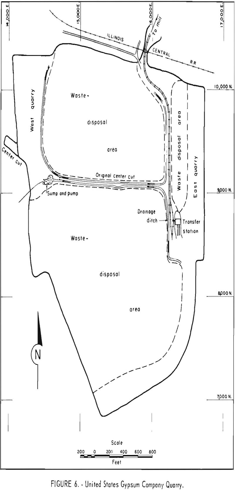
Use of scraper units has brought about a change in the stripping procedures that has increased the efficiency and decreased the cost of the entire quarry operation. In the East quarry the top 25 feet of the overburden is removed by scrapers and transported to the spoil area which had previously been leveled with dozers. This decrease in the volume of backcast material has eliminated the need for berm walls and has increased extraction 3 to 5 percent. The maximum haul for spoil in the East quarry is 1,800 feet. A dragline completes the rough stripping to the surface of the deposit. Final cleaning is accomplished by a Bucyrus-Erie 22B clamshell, followed by a Gradall. The clamshell removes the bulk of clay and sand from the erosion channels and the hydraulically operated Gradall, a very versatile piece of equipment well-suited to this type of work, removes a very high percentage of the remaining waste, leaving a minimum amount of hand-shovel work. The East quarry cut is approximately 4,000 feet long (fig. 6).
In the West quarry all the stripping is done with the scraper fleet, utilizing a D8 tractor with a D337 engine as a pusher. All loading and dumping are done downgrade. The cleaning procedure is the same as in the East quarry. The length of the present cut in the West quarry is 2,400 feet; the length of haul is 2,400 feet.
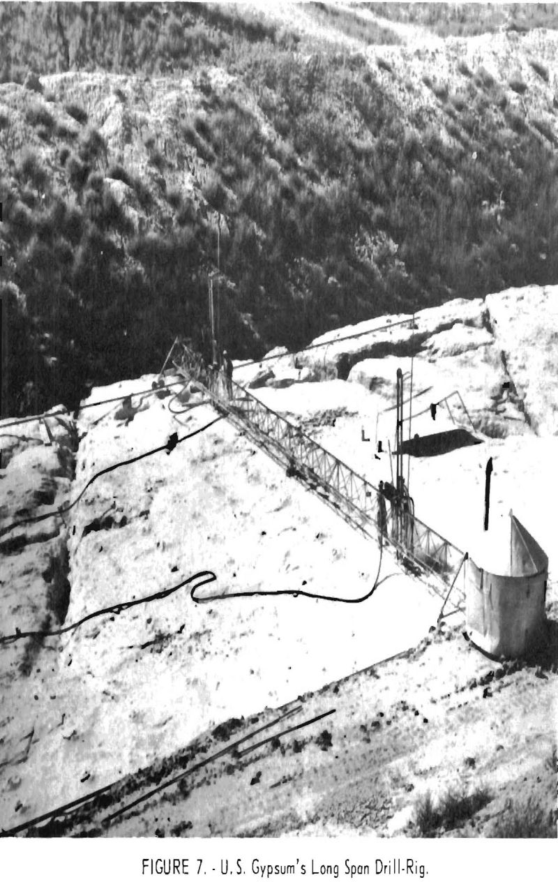
Because of the channeled surface, the use of wagon drills in most parts of the quarries is not feasible; however, the use of the heavier drills is desirable. To overcome these adverse conditions, the company has designed and built a unique drill rig (fig. 7). It consists of a steel truss, approximately 100 feet long, which spans the cut and is supported on each end by a modified “A” frame with four flanged wheels that run on movable rails. The top member of the truss supports two Gardner-Denver 89 drifters in vertical position and can be moved along, the truss manually to any desired hole location. Upon completion of a row of holes, the drill rig is moved 6 feet to the next row of holes to be drilled. With movable rails spanning the uneven bench surface, no difficulty is experienced in moving.
Compressed air is supplied to the East quarry for distances up to 5,000 feet by a stationary, Burry, 1,000-c.f.m., electrically driven compressor. Air is supplied to the pneumatic equipment in the West quarry by a Gardner-Denver No. 600 rotary, diesel-driven, portable compressor.
The height of the benches ranges from 10 to 30 feet. Blastholes are drilled on a 6- by 6-foot grid to a depth allowing approximately 18 inches of gypsum to remain as the floor of the cut. Fifteen to seventeen holes comprise one row across the bench. Enough rows are drilled in each round to produce approximately 15,000 tons per blast. The number of rows ranges from 17 to 30, the required number being partly determined by the height of the bench.
Ingersoll-Rand 1-¼-inch-diameter drill steel with throwaway bits are used. The average footage per bit is 3,500 feet. The starting bit is 2-½ inches and the bottoming bit 2 inches.
The holes are loaded with du Pont Gelex No. 2 and No. 5. Gelex No. 2 is used as the primer cartridge and is loaded in the bottom of the hole with the remainder of the charge being made up of Gelex No. 5. Cartridges are 1-¾- by 16-inch, and approximate respective strengths are 45 and 30 percent. To increase fragmentation the holes are loaded in three decks, drill dust being used as stemming. The amount of dynamite used per hole is variable and depends upon the location and depth of the hole and upon the surface erosional pattern and its intensity. Holes are detonated by Primacord, using 17-millisecond delays between the rows. Benches are shot against a buffer left from the previously blasted bench section. This buffer of broken rock prevents fly-rock and reportedly aids fragmentation of the soft, friable gypsum formation. When secondary blasting is required, the boulders are drilled with a jackhammer, loaded, and fired by Quarrycord and thermoconnectors. Explosives are stored in a wood-framed, sand-filled, metal exterior magazine approximately 1 mile from operations. This building is underground on three sides, wooden-floored, and ventilated.
The broken rock in the East quarry is loaded into 15-ton, Euclid, rear-dump trucks by a Bucyrus-Erie 88B shovel, with a 3-½-cubic-yard-bucket and transported to the transfer station on the west side of the East quarry. The average haul is 1,800 feet.
Loading in the West quarry is accomplished with a Bucyrus-Erie 54B shovel, with a 2-½-cubic-yard-bucket also loading into 15-ton Euclid trucks. The average haul is approximately 3,000 feet. Maximum haulage grades are 5 to 7 percent.
With elimination of the berm walls to retain backcast material, the 1-½ to 2 feet of gypsum left in the floor of the quarry for a roadbed can now be recovered in the East quarry. As the face of the quarry is advanced easterly, the west part of the quarry floor is blasted and loaded by the Bucyrus-Erie 54B shovel temporarily moved from the West quarry. This results in almost 100- percent extraction. As the West quarry face advances, the same salvage practice will be utilized in that area.
The Woodford haulage system is used from the transfer station to the mill. It consists of eight 11-ton-capacity, rocker-type cars, each individually driven by electric power from a third rail carrying 250 volts d.c. current. One control station is located at the transfer hopper and the other at the mill end of the track. Each operator controls the cars in his section until they come into the view of the other operator. At the mill terminal (5,000 feet from the quarry transfer station) the rock is dumped into an Allis-Chalmers Superior- McCully gyratory crusher, where it is reduced to minus 5-½ inches. The gyratory discharge is then fed into a Jeffery hammermill and reduced to minus 2-½ inches, which is millfeed size.
The drainage problem is sometimes quite severe, depending upon seasons, precipitation, and runoff. A connecting drainage ditch is maintained in both the East and West quarries, which terminates in a sump in the West quarry. A 12-inch Ingersoll-Rand centrifugal pump at the sump discharges into surface drainage west of the West quarry face. A ditch is now being constructed to the west, which will provide gravity drainage of the quarry water. This ditch, running obliquely to the face, will become part of the West quarry workings and actually is the center or initial cut.
Bestwall Gypsum Co.
General
The Bestwall Gypsum Co. property consists of about 600 acres. The plant is approximately 5 miles southeast of Fort Dodge (fig. 4).
The property was exploited in the past by the Certain-Teed Corp. and was only recently taken over by the Bestwall Gypsum Co. In October 1945 it was decided to abandon the underground mine and change to surface mining methods. Stripping was started immediately, and early in 1946 the first crude gypsum was quarried. The deposit, as exploited, is of high purity, consistent throughout the mineable area. The gypsum averages 23 feet in thickness and is overlain by glacial drift averaging 55 feet in depth.
Present production is approximately 1,000 tons of crude gypsum per day, the bulk of which is calcined for use as plaster or in fabricated products. A small amount is sold in crude form to cement plants or for other purposes.
The main company office is at 120 E. Lancaster Ave., Ardmore, Pa. Myron Read is in charge of the local operations, with offices at the company plant.
Exploration
Prospecting and exploration are carried on, when required, with a Parmanco skid-mounted auger drill driven by a gasoline engine. A complete and comprehensive exploration program during the early life of the quarry has virtually eliminated the necessity for present-day exploratory work. The original exploration program called for 4-inch holes on 200-foot centers. At the moment only routine engineering procedures, such as plotting changes in grade and thickness in the vicinity of the quarry workings, are required to keep such information up to date.
Development and Mining
Overburden at the Bestwall operations is composed of 2 to 3 feet of soils underlain by 50 to 60 feet of glacial drift and gumbotil. The gypsum ranges from 20 to 27 feet in thickness and averages about 23 feet.
The original stripping operations exposed the gypsum for a length of about 1,500 feet and a width of 75 feet. Spoil from this cut was cast on the surface to the west. This stripping was done under contract, as was the initial mining operation. Equipment used was a 3-cubic-yard, diesel-powered, walking dragline with a 100-foot boom. Bank slopes were carried on a 1-½:1 slope.
The company-operated equipment now used in stripping is a 5-cubic-yard, Bucyrus-Erie, 7W, electric-powered, walking dragline with a 180-foot boom.
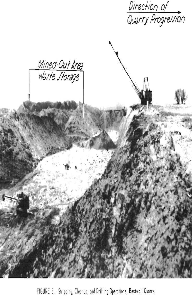
Overburden is removed as close as possible to the surface of the gypsum and is disposed of in the previously completed cut (fig. 8). Stripping is conducted on a two-shift per day, five-day week basis.
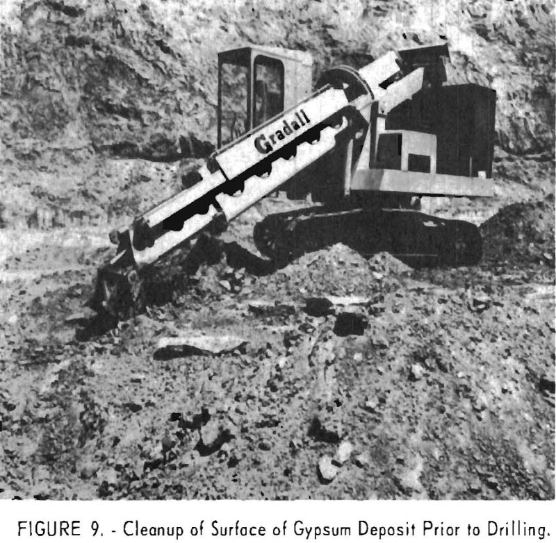
After removal of most of the overburden, the cleaning operation is completed with a Warner-Swasey crawler-mounted, diesel-powered, hydraulically operated Gradall (fig. 9), operating in conjunction with a D8 bulldozer. Previously, the 12 to 18 inches of overburden was removed by small draglines, shovels, and hand labor. The numerous crevices, ranging from 1 to 4 feet in width and up to 3 feet in depth, were all hand-cleaned. In addition to cleaning the surface, the Gradall can efficiently clean the crevices. The unit deposits the cleanup in conveniently located piles, to be removed by bulldozer or dragline. Enough rock surface is kept clean to prevent interference with the drilling operations.
The drill-hole pattern is a grid with holes spaced on 6-foot centers. Drilling equipment consists of two Ingersoll-Rand X71WD drifters, each with hydraulically controlled drill columns mounted on a jumbo improvised from a Farmall tractor. One and one-quarter-inch hexagonal , sectional steel in 8-, 16-, and 24-foot lengths, with 2-5/8-, 2-½, and 2-3/8-inch Timkin detachable, side-hole rock bits, are used. The holes are drilled to penetrate the gypsum formation. All drilling is done dry. One drill shift per day is adequate to meet normal production requirements.
Gelex No. 2 and Gelex No. 5 in 2- by 16-inch cartridges are used for blasting. The hole is loaded first with five sticks of Gelex No. 2 and then with Gelex No. 5 to within about 1 foot of the collar. It is then tamped with drill cuttings. Normally, six rows of up to 12 holes each constitute a shot. The holes in each row are wired in series, and the rows are connected in parallel. In the first row instantaneous and No. 1 delay primers are alternately spaced. In the second row alternate No. 1 and No. 2 electric delays are used. The third, fourth, and fifth rows are loaded in the same manner, with progressively longer delays. All the holes in the sixth or last row are primed with No. 6 delay electric caps. Electric power for the blasting circuit is supplied by a battery and condenser-type blasting machine. A considerable amount of broken gypsum is left against the face of the cut to cushion the blast. Little secondary blasting is necessary, since the gypsum usually breaks to minus 36 inches. Material of this size is readily handled by both the shovel and crusher.
The broken rock is loaded into trucks by a 2-½-cubic-yard crawler- mounted, Northwest 80D diesel shovel. The haulage equipment consists of two Euclid 36FD and one Euclid 80FD 15-ton end-dump trucks, which operate between the loading shovel and the quarry crushing plant. Haulage distances are 800 to 2,000 feet.
The crushing plant is centrally located to equalize haulage distances from the quarry working faces. Rock is crushed to 6 inches and under, which increases the efficiency of the truck haulage to the mill by permitting full-capacity loading. A 42-inch, Pioneer, Oro, apron conveyor moves the gypsum from the truck dump hopper to a Pioneer 3042RB 42- by 30-inch jaw crusher. The crusher is driven by a 125-hp. slip-ring motor operating at 600 r.p.m.
The broken gypsum discharges directly onto a 36-inch belt conveyor. This 455-foot-long conveyor, inclined at 18°, is driven by a 50-hp. induction motor through a gear-speed reducer and V-belt drive. The belt speed is about 270 feet per minute and will handle 200 tons per hour. The belt discharges into a 200-ton-capacity conical bin on the surface at the edge of the quarry. Rock is drawn from the bin into trucks through pneumatically operated gates, weighed, and transported 2.3 miles to the mill. The haulage equipment consists of three Mack LJ5W and one Mack B715T 22.5-ton-capacity diesel-trucks. The normal haulage rate per truck is three round trips per hour. The haulage road is well maintained and has no steep grades.
An office and maintenance shop are near the surface storage bin. Compressed air for all quarry operations is supplied by a Chicago Pneumatic, 1,000-c.f.m. air compressor, driven by a 175-hp., 440-volt, synchronous motor.
National Gypsum Co.
General
The National Gypsum Co. plant and quarry are about 3 miles south of Fort Dodge, Iowa, and embrace about 650 acres.
Before 1944 the entire National Gypsum Co. output came from an extensive room-and-pillar mine formerly owned and operated by the Universal Gypsum Co. The early operators had worked the mine for many years but had done little to recover the pillars or the gypsum left in the back and floor. Approximately 50 percent of the original reserves remained in the mine when the National Gypsum Co. took over control of the property in 1937. From 1937 to 1947, underground mining consisted mainly of robbing the pillars, back, and floor.
Surface mining was started in 1944; and both surface and underground activity was carried on until 1947, when the underground operation was completed and the mine abandoned. Since that time the entire production has come from the quarry.
The main company office is in Buffalo, N. Y. John Pitts, Works Manager, is in charge of the Fort Dodge operations.
Exploration
The method of exploration is consistent with the standard practice in the district. Parmanco auger drills with 4-inch bits are used. Holes are spaced on approximately 200-foot centers, except when the fringes of the deposit are delimited. Very little actual sampling is done, as the overall purity of the deposit is consistently high. The thickness of the gypsum is determined by the rate of advance of the bit, the action of the drill, and the cuttings. All holes are surveyed and their locations, depth of overburden, and thickness of gypsum are recorded on the proper maps.
Development and Mining
The thickness of the flat-lying deposit ranges from 18 to 25 feet, and averages 23 feet. Overburden, which is 50 to 65 feet deep, consists of two to three feet of soil, 15 feet of yellow clay, 30 feet of blue clay, and 5 to 6 feet of yellow clay. Stripping ratio of waste to rock is 2.6:1.
Stripping is maintained well in advance of the quarry face and, as with all quarry operations, is conducted on a single-shift, 5 day-per-week basis. Stripping equipment consists of two 15-cubic-yard Allis Chalmers HD16 scraper units, one HD19 pusher, one 15-cubic-yard Caterpillar D8 scraper unit, one Caterpillar D8 dozer, and two 18-cubic-yard Euclid 16 TDT and 68 FDT rubber-tired scraper units. A 4-ton hydraulic ripper, converted to cable control, is used for breaking frozen ground when stripping is necessary during the winter. Winter stripping is avoided if possible, and an effort is made to complete enough stripping during the favorable seasons to keep the high-cost winter stripping to a minimum.
One scraper unit is held as standby equipment, being kept in repair and ready to replace any operating unit. The scraper units usually work en echelon. Maximum haul distance is 2,000 feet, with a minimum of 300 feet. Spoil material usually is disposed of in the exhausted quarry workings, although some material is placed on the surface in barren areas. Each 150- by 500-foot cut presents its own stripping problems as to method of attack and disposal. A cut averaging 55 feet in depth can normally be prepared for cleaning and quarrying in about 3 months. Bank slopes are maintained on 1-½:1 ratio.
When the scrapers have removed as much of the overburden as possible, cleaning operations are begun. The uneven surface of the gypsum bed is cleared using a 1-cubic-yard-capacity Sargent dragline fitted with a ¾-cubic-yard bucket.
Present quarry practice is to carry the face in a single bench approximately 20 feet high, leaving about 2 feet in the bottom to maintain a substantial roadbed for trucks and equipment. The pattern of stripping and mining is governed somewhat by lease agreements.
Drilling equipment consists of a rubber-tired wagon drill mounting a Gardner-Denver, D99, percussion quarry drill. Compressed air is supplied by a Gardner-Denver, rotary, 600-cubic-foot capacity, portable compressor maintaining 95 to 105 pounds of pressure. Drill steel is 1-¼-inch hexagonal, threaded for detachable bits. There is no bit-size change, all holes being drilled with 2-½-inch bits.
The blasthole drill pattern is a staggered grid, with holes spaced on 6- foot centers and rows spaced 7 feet apart. Holes are drilled to a depth of 20 feet, bottoming about 2 feet above the base of the gypsum formation.
Holes are loaded with du Pont Gelex No. 2 and No. 5 placed in three decks. Each deck occupies about 4-½ feet of hole and consists of two and one-half 2- by 6-inch cartridges of Gelex No. 5 and two 2- by 8-inch cartridges of Gelex No. 2. One to two feet of drill-dust stemming separates the decks with the top 3 feet of the hole being stemmed. Primacord is used as the detonator, with 17- millisecond Primacord delay connectors between the rows (fig. 6). The number of holes shot in each blast varies and is determined by the pit foreman. At present, the company is experimenting with commercial grade, nitrate fertilizer as an explosive.
Very little secondary blasting is required. Usually, oversize boulders are broken by a 4,500-pound drop ball. As the quarry face advances, the 2 feet of gypsum left in the quarry bottom is removed, except for that required as a roadbed for the next cut. This bottom rock is drilled and blasted. The holes are on 4-foot centers and drilled to within 5 or 6 inches of the clay at the base of the formation. These holes are loaded with 1-½ to 2 sticks of 30- percent gelatin dynamite.
The crawler-mounted loading equipment consists of a 2-cubic-yard Loraine shovel and a 2-½-cubic-yard Northwest shovel. At the present production rate the shovels handle about 1,000 tons per day on a single-shift basis.
Haulage equipment consists of four trucks, three 15-ton Euclids and one 25-ton Dart; one truck usually is maintained as a standby. Haulage distance from the shovels to the mill is ¾ mile. The road is unsurfaced but is maintained in good condition by an Allis-Chalmers AD-3 motor grader and is virtually level, except for a short 7-percent grade out of the pit.
Maintenance and repairs on all motorized equipment connected with the quarry operations are made at a well-equipped shop near the quarry.
As with other operations in the area, the amount of water flowing into the quarry is sufficient to require a fairly large pump installation. In the present quarry operations the water is collected in sumps, pumped to the surface, and discharged into the natural drainage. The pump installations consist of one electrically driven, 5-inch-discharge, centrifugal pump with a rated capacity of 1,200 g.p.m. and two gasoline-driven, centrifugal pumps with rated capacities of 700 and 150 g.p.m.
The company employs 232 hourly employees in the mill and quarry. Of this total, 25 are connected with the quarry operations.
A stockpile of about 30,000 tons of crude gypsum is in the vicinity of the mill. All crude gypsum is calcined; about 67 percent goes into fabricated products, such as wallboard, and 33 percent into various types of plasters.
The small amount of electric power used in connection with the quarry operations is purchased from the Iowa-Illinois Gas & Coal Co.
