Table of Contents
The breaking of rock by explosives occurs so rapidly that the details of the phenomenon cannot be observed by the unaided eye. High- (frame-) speed motion pictures offer a means of slowing down the blasting action so that the various phases of the process can be observed and studied. During the last 10 years, both in this country and abroad, the high-speed camera has been increasingly used as a tool for studying blasting phenomena. The Bureau of Mines has been using a high speed camera in connection with its rock blasting program since 1953.
Certain qualitative information can be obtained from a high-speed photograph of a blast. For example, the events which follow a quarry blast, such as the first rock movement, the order in which a multiple-hole round is detonated, the confinement or blowout of stemming, the escape of detonation gases from the shothole or through the broken rock, and the shape or form of primary rock movement, can be observed. This information is useful in determining the cause of misfires, poor loading or firing practices, or improper burden or spacing of shotholes. In addition, there can be obtained from high-speed pictures a number of quantitative measurements, including the acceleration, velocity, and direction of the fly rock, the initial time of detonation, the firing time of millisecond or other delay detonators, and the size of rock fragments. The fly-rock data is of particular importance for studying the physical processes involved in breaking rock with explosives.
This report describes the equipment and operating procedures for making high-speed photographs of quarry blasts and the method of analyzing the data. Correction factors for the camera orientation angles are given graphically, and the errors that can be expected in the various measurements are discussed.
Description of Equipment
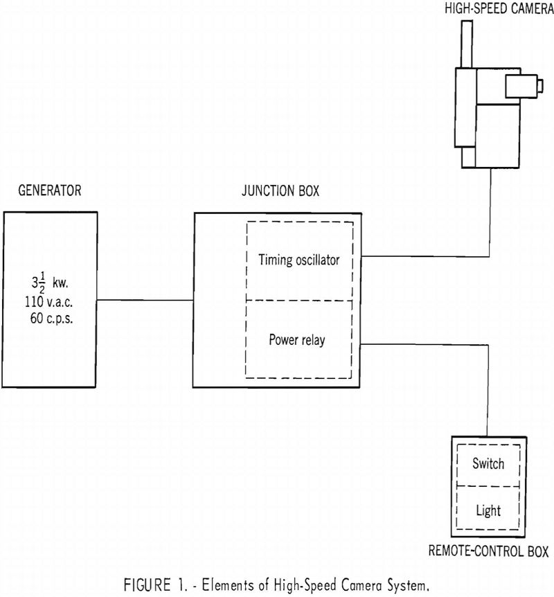
The field equipment used by the Bureau for making high-speed motion pictures of blasting consists of an Eastman high-speed 16-mm. camera, a junction box containing a timing oscillator and a power relay, a remote-control box, a light meter, and a portable gasoline generator. A block diagram of the system is given in figure 1. A time-study projector and an adjustable screen are used in the laboratory to study the processed film.
High-Speed Photographic Equipment
The camera uses a rotating prism-type shutter that provides a speed range of 1,000 to 3,200 frames per second. The image exposure occurs in 1/5 of the time required for one frame to pass the lens. Thus, for a camera speed of 3,200 frames per second the exposure time per frame is 63 microseconds. The lower limit of time measurements also depends on the frame speed, as the smallest time interval that can be resolved corresponds to 1 frame. For the speed range of this camera the interval between frames is approximately one to one-third millisecond.
A light source is included in the camera for time-marking the film. A 200-cycle-per-second vibration-reed oscillator is used to actuate the time-marking light in the camera. The oscillator is temperature stable within 1 percent over the temperature range of 20° to 115° F. As the time marks on the film are accurate to within 1 percent, the film speed, and consequently the time measurements, can be determined within 1 percent.
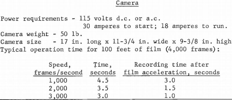
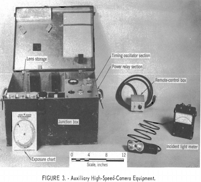
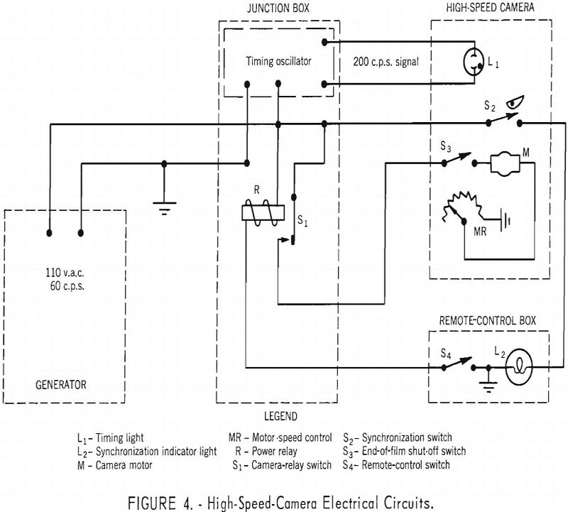
A synchronization switch is included in the camera and closes when a preselected film footage has passed through the camera. Normally this switch is set to close when the frame speed has reached about 80 percent of the final selected value. When this switch closes, a pilot light is turned on momentarily in the remote-control box. This light is used to indicate the instant the round should be fired. Provision is also made for turning off the camera motor after either 50- or 100-foot film runs. The camera and four interchangeable lenses are shown in figure 2, and their characteristics are given in table 1.

A Brunton transit was mounted on top of the camera so that the inclination of the optic axis could be measured. A level was also mounted on the camera, normal to the optic axis, so that sidewise tilt could be eliminated.
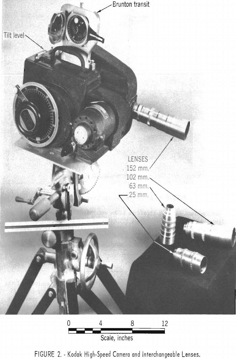
The camera and junction box usually are placed near the blast. In instances when the camera is within 100 feet of the blast, a steel enclosure is used to protect the camera and junction box from fly rock. The camera is turned on with the switch in the remote-control box, which may be 2,000 feet or more from the camera. The accessory camera equipment is shown in figure 3 and the control circuit in figure 4.
Quarry-blast pictures should be taken under direct and preferably bright sunlight. A Weston incident-type light meter is used to obtain light readings, and the lens aperture required for a given camera speed is determined from an exposure chart. A fast black and white negative film (exposure index-daylight=320) is used in the camera; positive prints are made for projection.
Projection Equipment
A Bell and Howell 16-mm time-study projector is used for analysis of the blasting motion pictures. The projection speed can be varied from 13 to 25 frames per second, either forward or reverse. Also, single-frame projection can be obtained by means of a handcrank. The projector is provided with a frame counter. A special heat-absorbing filter is built into the projector to prevent burning the film in single-frame projection.
The projector is mounted in a dark room on a rigid frame so as to project an 18- by 24-inch picture on a vertical screen. The film plane and the screen are parallel. The screen can be displaced horizontally or vertically by means of handcranks. This adjustment is necessary in single-frame projection to correct for small displacement of the image from one frame to the next.
Theory of Measurements
Generally, two cameras must be used stereoscopically to permit measurement of the displacement and direction of moving objects such as fly rock. However, in preliminary investigations it was found that for both crater and quarry blasting the fly rock moves normal to the face from which it was broken. For this case the displacement and velocity can be determined with one camera, provided that corrections are made for the alinement of the camera with respect to the direction of the fly rock.
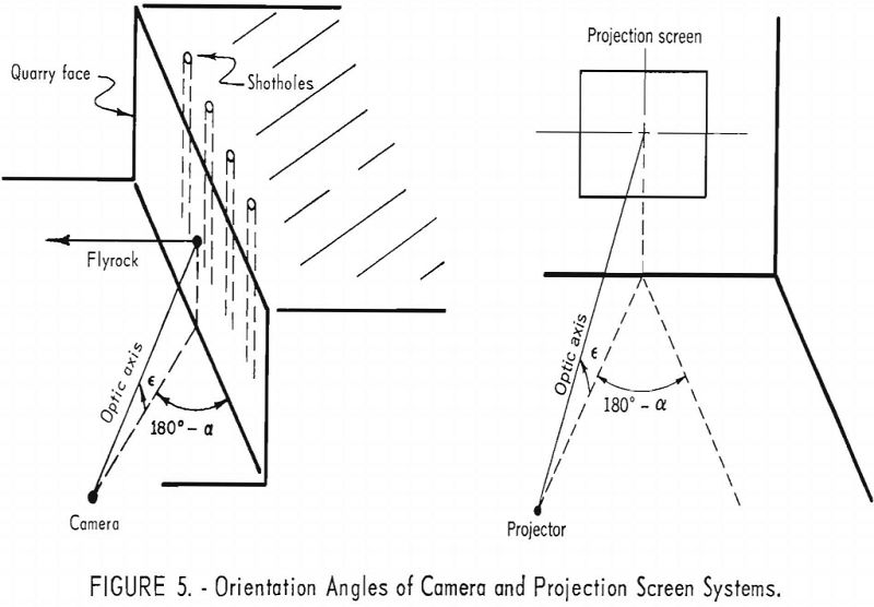
In photographing crater shots the camera is always oriented so that the optic axis is normal to the fly-rock direction. For this orientation the angle corrections are zero, i.e., a unit of fly-rock displacement is directly proportional to a unit of displacement on the film (or projection). However, in photographing a multiple-hole quarry blast it has been found that the best information can be obtained when the camera is alined so that the optic axis is at an azimuth of about 30 degrees from the quarry face. Moreover, as the camera is usually placed on either the floor or rim of the quarry, the optic axis must be inclined upward or downward (fig. 5) so as to strike the approximate center of the quarry face. If the camera is so oriented, correction factors must be applied to the displacement measurements made on the film (or projection).
These corrections can be accomplished in either of two ways:
- By orienting the projector with respect to the projection screen so that the azimuth and elevation are the same as in the quarry (fig. 5). For this condition a unit of displacement on the projection screen will be directly proportional to a unit of fly-rock displacement. This method has the disadvantage that an elaborate and rather awkward arrangement must provide for orienting the projector and/or the projection screen.
- By orienting the projector with the optic axis normal to the projection screen so that the correction for the azimuth and elevation angles can be calculated. This calculation is discussed in the following section.
Correction for Camera Orientation
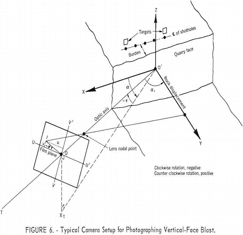
An idealized camera setup for photographing a single-row blast of a vertical quarry face is shown in figure 6. The quarry is defined in terms of an X-Y-Z coordinate system. The quarry face is assumed to be parallel to the XZ plane with rock motion at right angles to the face in the O’ Y direction. The camera system is defined in terms of T-U-V coordinates with the film plane VU perpendicular to the optic axis OT.
The orientation of the camera with respect to the quarry face can be specified by the three angles, azimuth, elevation, and tilt. When these three angles are zero the camera optic axis is alined along the X axis and the film plane VU is parallel to the ZY plane. Azimuth, α, is a counter-clockwise rotation of the projection of the camera optic axis in the horizontal plane about the Z axis to the position Xt. Elevation, ε, is a vertical rotation of the optic axis from point Xt to some point O. The tilt angle, P, is a rotation of the V and U axis about the T axis; however, this angle is normally maintained at zero degrees so that the camera orientation is given only in terms of α and ε.
The transformation of a rock-displacement coordinate Y to film-plane coordinates u and v is given by
u = Y cos α……………………………………………………………….(1)
v = Y sin α sin ε………………………………………………………..(2)
A blasted quarry face moves more or less as a mass, and it is usually impossible to follow the flight of a particular rock. Hence, to determine the fly-rock velocity it is necessary to measure the displacement of the forward edge of blasted mass along a vertical line. As the measurement is made on the film (or projection) it must be made along the line OI (fig. 6). This line is rotated about the T axis through the angle σ and is related to α and ε as follows :
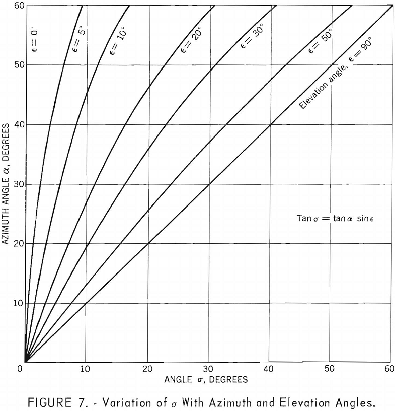
tan σ = v/u = tan α sin ε……………………………………….(3)
The variation of σ for different values of α, and ε is given in figure 7.
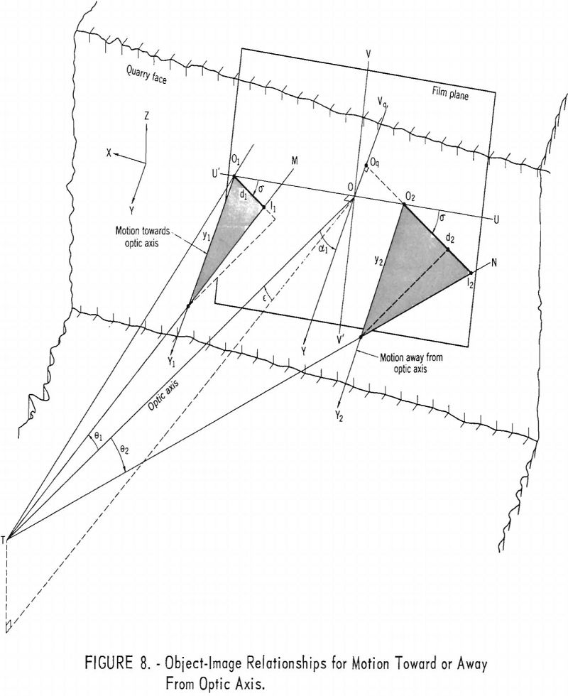
The displacement measurement on the film (or projection) must also be corrected because the motion is either toward or away from the optic axis. This is illustrated in figure 8, where the film plane is superimposed on the quarry face. The projection of the rock motion in the film plane is O1I1 when the fly rock is moving towards the optic axis and y1 is given by
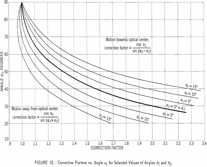
y1 = d1 cos θ1/sin(α1 – θ1)………………………………………………..(4)
When the displacement is away from the optic axis, O2I2 is the projection of y2 in the film plane, and y2 is given by
y2 = d2 cos θ2/sin(α1 + θ2)……………………………………………..(5)
where, in figure 8
d1 = image displacement along lines O1I1
d2 = image displacement along lines O2I2
θ1 ≅ < OTM, that is θ1 = < OTM when O1I1 passes through O,
θ2 ≅ < OTN, that is θ2 = < OTN when O2I2 originates at O,
α1 = < TOY
and where
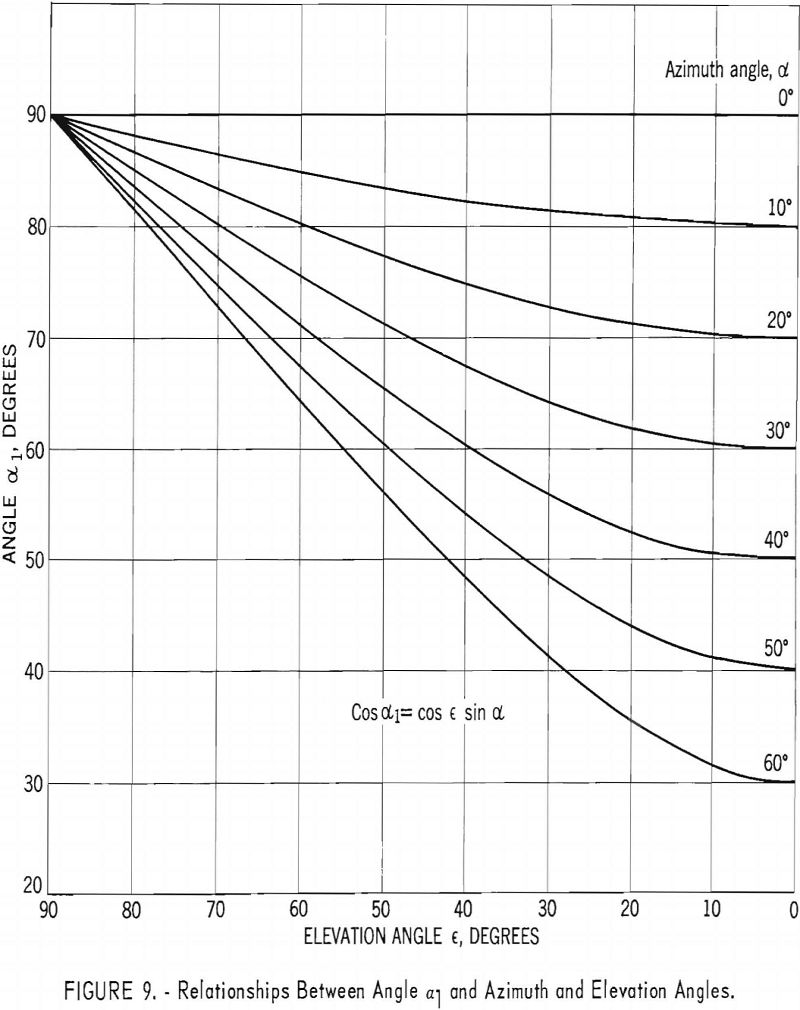
cos α1 = cos ε sin α……………………………………………………(6)
A graph showing this relationship for different values of α1, ε, and α, is shown in figure 9. The correction factors for various values of θ1 and θ2 and α1 are also shown by graph in figure 10.
Equations (4) and (5) hold for measurements along any line OI in the film passing through the origin O. If the line on which the displacement is measured does not pass through the origin, a quasi-origin, Oq, is chosen along the axis OVq. (See figure 6.) However, it has been found that this displacement of the origin has only a very small effect on the angles α and θ; consequently, all angle corrections are made as though the rock displacement passes through or originates at O. Hence, equations (4) and (5) can be used with only negligible error for measurements anywhere on the film plane.
Gravity Effects
Rock broken from a vertical quarry face will be accelerated downward by gravity. The instantaneous fly-rock velocity at a given time, neglecting frictional effects, is the resultant of the initial horizontal component of velocity and the vertical velocity component due to gravity. However, if the horizontal component of displacement (measured in the direction of OI, as in figure 6) of either a moving rock fragment or the vertical forward edge of a blasted rock mass is measured, no correction for gravity is required.
If the free face lies in the horizontal plane, such as in a crater test, the fly rock moves vertically upward. If frictional effects are neglected, the initial fly-rock velocity is given by

where
Vo = initial fly-rock velocity,
z = vertical rock displacement,
t1 = time interval,
g = acceleration of gravity.
Scale Factor
The scale factor is the ratio of the object to image displacement. If the image displacement is measured on a projection screen, the scale factor is the reciprocal of the combined camera and projector magnification. The scale factor p is given by

where
uc = camera-lens-to-object distance,
vp = projector-lens-to-image distance,
F = focal length of projector lens,
f = focal length of camera lens.
If the projector-to-screen distance is fixed, all quantities on the right side of equation (8) except uc are constant.
The scale factor obtained by equation (8) can be checked by determining the ratio of the surveyed distance between targets placed at a site and the corresponding target-separation distance measured on the projection.
In the use of the camera the width of field (normal to optic axis) required in a particular test is often specified. As a first approximation the field width at a given distance can be calculated from the following relationship:

where W = width of field at uc distance,
Wn = negative width of field,
Ratios for the four lenses have been calculated on this basis and are presented in table 2.
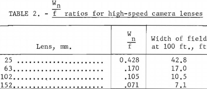
In projecting the film, about 10 percent of the field width is lost through cropping, and allowance should be made for this in applying the above factors.
Time of Initial Movement
The high-speed camera can be used to measure the time between the detonation of a charge and the initial rock movement. The accuracy with which this measurement can be made depends on camera speed, the scale factor, the minimum displacement that can be resolved on the film or screen, and the velocity of the object.
Let d be the smallest distance that can be resolved on the screen. Then, with a scale factor p, the minimum detectable distance, D, in the field of view is
D = pd…………………………………………………………(10)
Furthermore, if the object is moving with an average velocity V, then the time t0 to travel the minimum distance that can be resolved in the field of view is
t0 = D/V = pd/V…………………………………………………(11)
The variation of minimum time with scale factor for several fly-rock velocities is given in figure 11.
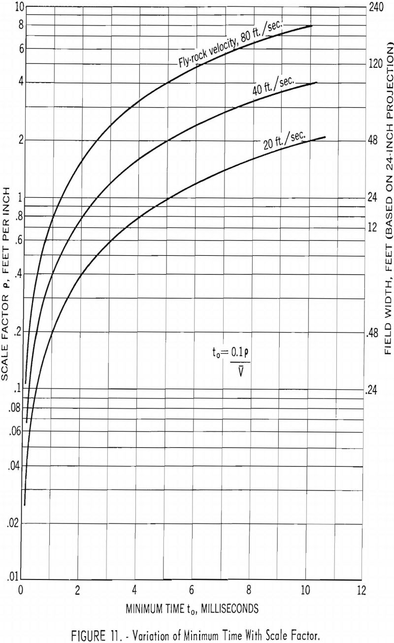
In quarry-blast photography, if the camera-to-object distance and the width of the field of view are large (as would be the case with a comparatively wide angle lens), the accuracy of the time measurement is low. For example, with a projected field of view of 24 inches, the minimum displacement that can be resolved on the screen is about 0.1 inch. Assuming an object velocity of 40 feet per second and a scale factor of 8 feet per inch (which would be obtained with a 25-mm. camera lens, a camera-to-object distance of 500 feet, and the specified projection-image size) the minimum time is, from equation (11),
to = 0.1 x 8/40 = 0.02 seconds
A significant determination of the time of initial movement should be much less than this. The time for initial movement of rock at the free surface can be predicted from the reflection theory of rock breakage. The minimum time, tm is given by
tm = B + Ds/Vp…………………………………………………..(12)
where
B = burden,
Ds = slab thickness,
Vp = propagation velocity.
Consider a typical quarry blast where the rock propagation velocity is 18,000 feet per second, the burden in front of the shothole is 10 feet, and the first slab thickness is 2 feet. Under such conditions the rock at the free face should be broken and moving in about 0.7 millisecond after the detonation of the charges. Obviously the 20-millisecond time resolved is too great for any initial movement to be detected. The minimum time can be reduced by decreasing the scale factor. This can be accomplished either by decreasing the lens to object distance or by employing a lens of longer focal length. As an example, consider a 152-mm. camera lens and a shot-to-camera distance of 100 feet. With the same projection setup the scale factor is 0.264 feet per inch and t0 = 0.7 milliseconds. The time of initial rock movement also can be determined by plotting rock displacements as a function of time and extrapolating to zero displacement. The above calculations were made on the basis of a camera angle orientation of a, = 0°. If Ct 4 0°, the object and image distance in equation (10) must be corrected accordingly.
The camera frame speed determines the minimum time that can be measured, i.e., the time corresponding to one frame. However, if the distance the rock moves in one frame is less than the corresponding 0.1-inch minimum resolution on the screen, an increase in camera speed will not improve the minimum time that can be measured.
Field Operating Procedure
The operating procedure for photographing a quarry blast is as follows;
- Select a camera position which will give the optimum results. Consider such factors as the particular advantage of small or large azimuth and elevation angles, the width of field, and the position of the sun at the proposed time of test.
- Rigidly mount the camera on a tripod at the chosen position. Select a lens of the proper focal length to afford the desired field of view. (See table 2.) Level the camera (sidewise tilt) and measure the elevation angle.
- Set up the targets used for checking the scale factor.
- Locate adequate secondary reference points in the field of view. A special effort should be made to select reference points that will not be obscured by the blast. The targets may serve as reference points if properly arranged.
- Determine the position of the camera with respect to the shotholes and the targets by a survey. Measure face height; shothole spacing, and burden. Obtain shothole explosive loading data. (See table 3.)
- Lay cable to the quarry firing position for remote triggering of the camera. Distances may vary from 200 to 2,000 feet, depending on local quarry conditions.
- Connect equipment and make a dry-run check of the camera operation.
- About 30 minutes before the shot, perform the following operations:
(a) Check the focus and field of view.
(b) Obtain a light reading with the incident-type light meter and determine the proper lens aperture. Set the lens f number accordingly.
(c) Turn on the timing oscillator. Check the time-marking light in camera.
(d) Load the camera with film.
(e) Set the camera speed.
(f) Set the synchronization switch for actuation after a selected film footage has passed through the camera. Set the motor shutoff switch for the length of film loaded.
(g) Record camera-lens operating data. - When the blast is ready for detonation, turn on the camera by means of the remote-control switch. The instant to fire the shot is indicated by the flash of the remote synchronization indicator light.
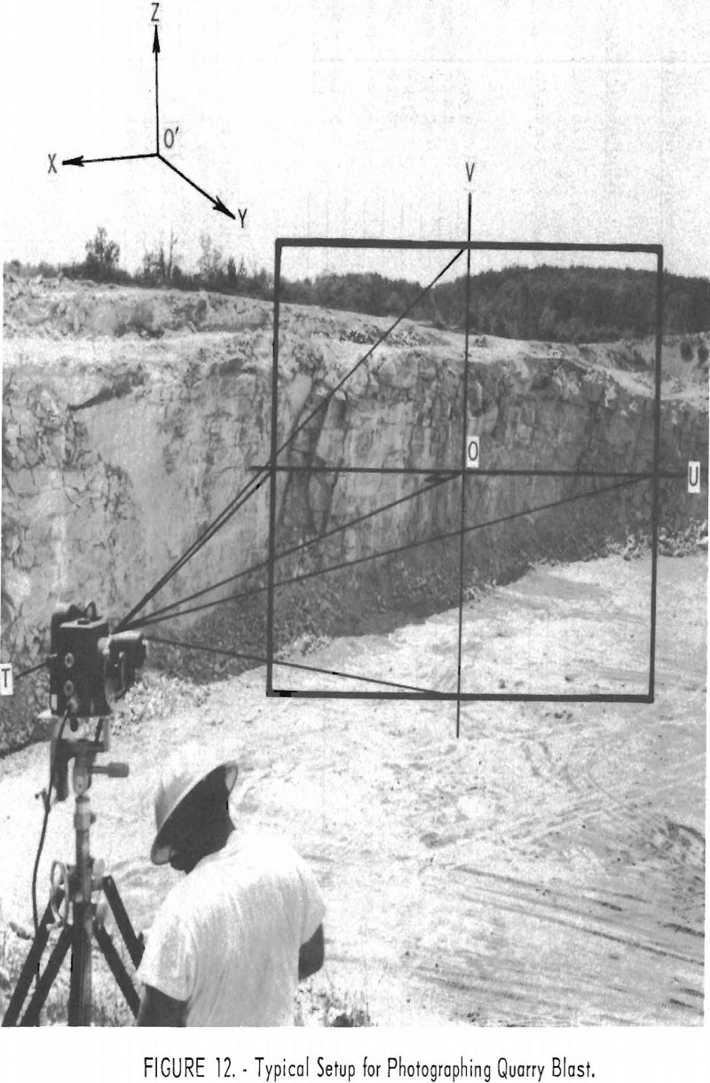
A typical high-speed-camera setup for a multiple-hole quarry blast is shown in figure 12. A chart showing the field data required for such a test is given in table 3.

Analysis Procedure
The analysis of high-speed motion pictures should be made as follows:
- Determine the time per frame by measuring the distance between the time-reference pips on the edge of the film at given frame intervals. Compute the time as follows:
Δt = w/NDt………………………………………………………………….(13)
where
Δt = time per frame,
w = width of one frame (7.6 mm.),
N = frequency of timing oscillator (200 c.p.s.),
Dt = distance between time-reference pips (mm.).
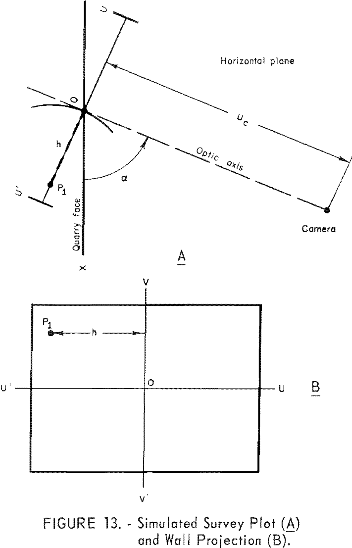
Plot time per frame against the frame number. Usually the first indication of the shot is designated as zero frame. - Make a survey plot (horizontal projection) showing the camera position, the quarry face, and a known reference point in the camera field of view. See figure 13(A.)
- Make a scale drawing of the film-plane projection showing the position of the reference point P1 as in figure 13(B). Let h be the horizontal distance from P1 to the vertical axis. On the survey plot draw an arc about point P1 of radius h times the scale factor. Draw a line through the camera position tangent to this arc. This line is the projection of the optic axis in the horizontal plane, and the azimuth angle, (X , is determined as the angle between this projection and the quarry face.
- Check the agreement between the scale factor given by equation (8) and the scale factor determined from the ratio of the surveyed distance between targets to the corresponding target separation measured on the projection. A disagreement of more than 5 percent indicates errors in either the scale factor calculations or the survey data. If the targets are not on a line normal to the optic axis the projected target separation distance must be corrected by equation (1).
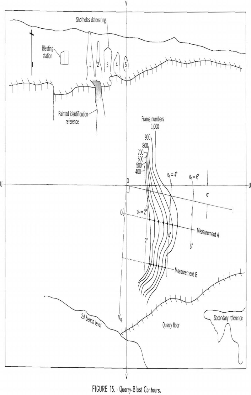
- Make displacement measurements of either the vertical forward edge of the blasted rock mass or an individual rock fragment. For the case of the vertical forward edge of the blasted rock mass, project the film onto a sheet of paper attached to the adjustable screen and draw in secondary reference points. At convenient equal intervals, such as every 20, 40, or 60 frames, draw contour lines outlining the position of the leading vertical
edge of the quarry face as the blasted rock moves outward, realining the screen with the secondary reference points for each observation. Determine the angle θ by means of equation (3) and draw in the line OI in figure 6 or any line parallel to OI along which a displacement measurement is desired. Make the displacement measurements between the initial and succeeding contours. Repeat the above procedure for the case of the individual rock fragment with the exception that the contours along the trajectory of the rock fragment must be projected back to the horizontal component of displacement OI, by lines parallel to the film axis VOV’. Displacement measurements are then made along the line OI as before. - Intersect the line OI with concentric arcs about the origin 0 of radius r = uctan θr where θr = 1°, 2°, 3°, etc. For lines parallel to OI (not originating at O) the same radius r is used; however, the lines are projected back to an imaginary point of origin Oq along OV’q ^ which is normal to OI. Read the angle θr covering each displacement measurement to the nearest 0.5 degree. Determine the angle α1 by means of equation (6), By means of equations (4) and (5) correct the displacement measurements for angle effects. Equation (8) is used for determining the scale factor for the camera-to-object distance scaled from the survey. Convert the corrected displacement measurements to field-object size by the scale factor.
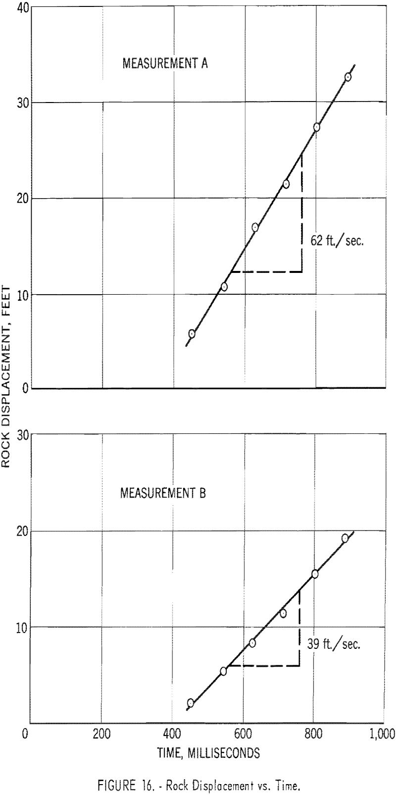
- Determine the fly-rock velocity by dividing the corrected displacement by the corresponding time as determined in step 1. If the fly-rock velocity is constant, the slope of the straight line through a data plot of corrected displacement versus time will yield the fly-rock velocity.
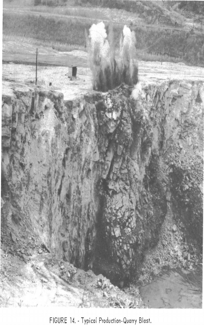
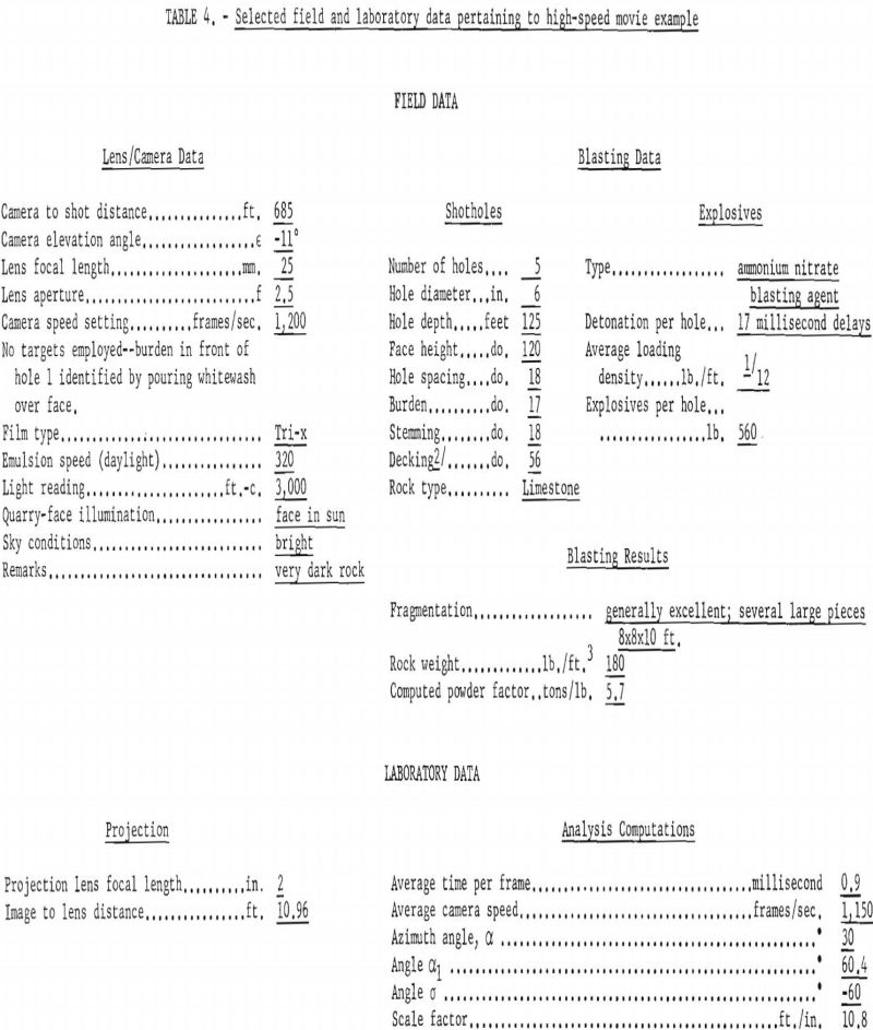
A photograph of a typical production-quarry blast is shown in figure 14. Figure 15 shows contours of the moving rock mass as determined by procedures given above. Contour lines were drawn at 100-frame intervals. Pertinent blasting and camera data relating to this shot are given in table 4. Plots of the displacement data versus time are shown in figure 16. The apparent bulging of the quarry face shown in figures 14 and 15 results from the type of deck loading employed at this quarry. A greater displacement and fly rock velocity occurs opposite the loaded portion of the hole (measurement A) than opposite the unloaded (decked) portion of the hole (measurement B).
