Table of Contents
After studying the factors which influence oil recovery from petroleum reservoirs and since the flow behavior of fluids in petroleum reservoir rock depends to a large extent on the properties of the rock, techniques of core study that yield new or additional information on the characteristics of the rock would contribute to a better understanding of petroleum reservoir performance.
Magnetic fields applied transverse to the direction of flow of a conducting fluid in a channel retard the rate of flow. The magnitude of retardation is related to field strength and channel half-width or radius. Hence, one would anticipate that magnetic fields might provide a technique for studying pore size in rock, either singularly or as an adjunct to the mercury injection technique of pore sizing.
Theory has been developed by several investigators that describes hydromagnetic flow in various shaped channels, and experimental verification has been obtained for straight tubes and capillaries. In general, a magnetic field will flatten out the velocity distribution profile and reduce the average flow velocity of a flowing conductive fluid. These effects are manifestations of the Lorentz force acting on the charge carriers in the fluid.
For straight uniform channels, the hydromagnetic equations of Hartmann, Shercliff, and others give mathematical relationships between the magnetic field strength, fluid conductivity, volume rate of flow, and radius or half-width of the channel.
Very little information concerning the flow of conductive liquids in porous media in the presence of a magnetic field was found in the literature. Morris and Pierce observed no change in the rate of flow of brine in rock samples on application of a magnetic field transverse to the direction of brine flow. The lack of an effect was probably due to the combination of low field strength and fluid conductivity with a small effective channel radius.
From the equations of Hartmann and Shercliff, it appears that observable changes should occur in the rate of flow of mercury through uniform capillaries with radii in the 100-micron range when a magnetic field of 0.25 weber/meter² is applied. A change in the volume flow rate should be marginally discernible in porous media if the effective hydromagnetic radius approximates the average pore size, and should be clearly observable if the effective radius is larger. The effect was sought experimentally in a reservoir rock sample and in synthetic samples.
Application of an electric current transverse to the magnetic field influences the flow rate of mercury in a channel. This effect should also occur in porous media.
This report discusses attempts to measure a change in the volume rate of flow of mercury through porous media under the influence of a transverse magnetic field and crossed electric currents and magnetic fields.
Theory
Clear Channels
When a conducting fluid moves in a magnetic field, a current is induced in the fluid which is perpendicular to the direction of flow and also to the magnetic field. The current density is given by
![]()
where σ and v are the fluid conductivity and velocity and B is the magnetic field strength. This induced current interacts with the field to produce a body force (F) on the fluid of
![]()
This force contributes a term to the Navier-Stokes equation for viscous incompressible flow. By applying appropriate boundary conditions, flow velocity can be related in a differential equation to the applied field strength.
Hartmann developed a theory for the flow of a conducting liquid in a rectangular channel when subjected to a transverse magnetic field. Germeles verified his results for channels of large height-to-width ratios.
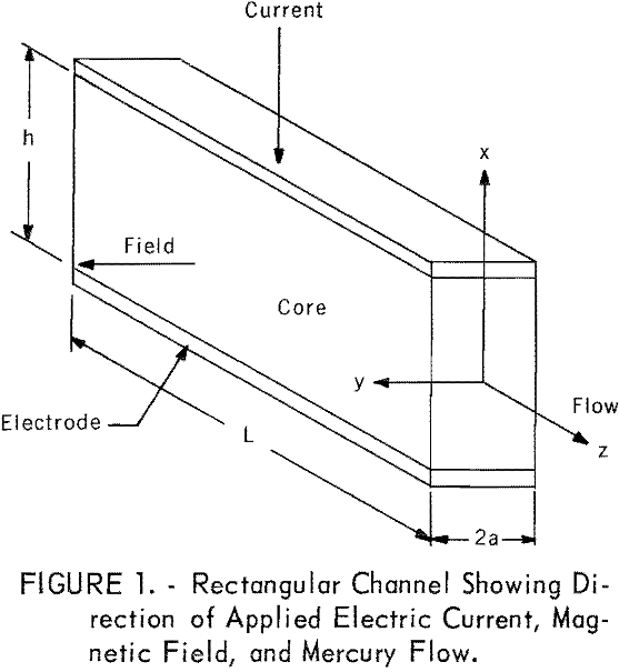
Hartmann studied a rectangular channel (fig. 1) of high aspect ratio (h/2a) with the applied field B in the y direction and the flow in the z direction; the channel had nonconducting sides, conducting top and bottom, and no external connection between the conducting plates. His development proceeds as follows.
The field, B, induces a current, J, in the -x direction in a flowing conductive fluid. The body force, due to the interaction of J and B, can be incorporated in the equation of viscous flow for a filament of fluid of height h and width dy at a distance y from the center of the channel to give

where P/L is the pressure gradient along the channel, η is the coefficient of viscosity of the fluid, and vm is the average velocity. The first term on the right is the drag on the fluid due to ordinary viscosity, while the second term represents the effects of the magnetic field.
Defining the Hartmann number
M = √σ/η Ba……………………………………………………………………(4)
and using the boundary values v = 0 at y = ± a, the solution to this equation is

From this, the volume rate of flow in the channel is

The nonmagnetic volume rate of flow in a rectangular channel is

Equations 6, 7, and 8 are related by the fact that the limit of f(M) is f(O) = 1/3. The fractional change in the flow rate due to the application of a magnetic field is then predicted to be

Hartmann extended his theory to cover channels of circular cross section by applying an empirically determined reduction factor of 0.51 to the M values used in equation 9. A more recent analysis of flow through nonconducting circular channels has been made by Shercliff. He found that Hartmann!s formula works for large values of M, but for circular tubes with values of M less than 1, he obtained the equation

Without a magnetic field, volume flow rate in a circular channel is given by Poiseuille’s law

Retaining only the first two terms in equation 10 gives the ratio

Porous Media
In applying the foregoing equations to flow in a porous media, two considerations arise: the pore size is in the millimeter-to-micron-diameter range, and the pores are not uniform straight capillaries but comprise a tortuous nonuniform interconnected network. It is assumed that size considerations do not disturb the validity of the theory since the pore sizes are still large compared with molecular mean-free paths.
The question of interest is whether a straight capillary bundle model can describe the hydromagnetic flow characteristics of the medium. If this can be done, then how does the distribution of capillary sizes in the model compare with the pore size distribution of the medium? In the case of a Gaussian distribution of channels, what single effective hydromagnetic channel radius fits theory to experiment, and how does this effective radius compare with the actual pore radii?
It might be assumed, since the actual pores are interconnected, that the value chosen for the capillary radius or half-width should be larger than the average pore radius. The extreme case would be to model the sample as a single rectangular channel with the same length as the sample and with the volume equivalent to the total pore volume. The following calculation illustrates the prediction of Hartmann’s equation for such a model. Hartmann’s values for the viscosity and conductivity of mercury of 1.6 x 10-² newton sec/meter² and 10 6 (ohm-meter)-¹, respectively, are used here. For a rectangular piece of rock 10 cm long, 2.5 cm high, and 0.7 cm thick, with a porosity of 40 percent, the equivalent single channel having the same length, height, and volume must be 0.28 cm wide. For mercury flow in this channel and a magnetic field of 0.25 weber/m², the Hartmann number from equation 4 is M = 8.8. Thus, using equation 9, there would be a 70-percent fractional change in the volume rate of flow due to the magnetic field.
A more realistic approach might be to consider that the radius or half-width approximates the average pore radius. If this radius or half-width is 100 microns, then the Hartmann number given by equation 4 is 0.63. Hartmann’s equation 9 gives a change in volume rate of flow of 2.5 percent for a rectangular channel, and 0.7 percent for a circular channel. Shercliff’s equation 12 gives a change of 0.8 percent.
If the effective radius or half-width is smaller than the average pore radius, then the variation of the pore radius in a sample with extremely small channel sizes might produce an effective Hartmann number of much less than 1. The change in the flow rate would then be difficult to resolve experimentally.
If a porous medium is modeled as a bundle of straight uniform capillaries with some distribution of radii, then the ratio of the flow rate with field on and off is
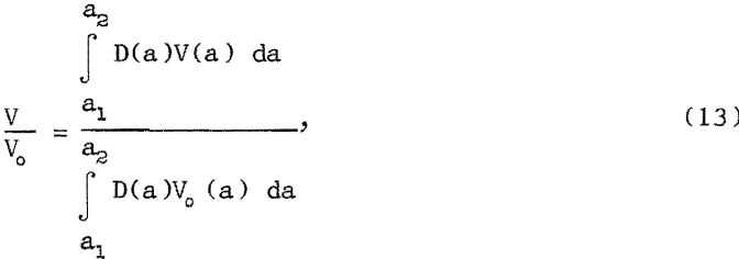
where D(a)da is the fractional number of capillaries with radii between a and a + da, a1, and a2 are the minimum and maximum radii in the distribution, and V(a) and Vo (a) are the flow rates for a single channel of radius a with and without the magnetic field, respectively.
Some data on pore-size distribution in reservoir sandstones are given by Tignor and others. The area distribution function for these sandstones is
D(A) = n’e -n ‘A……………………………………………………………(14)
where D(A) is such that the product D(A)dA is the fractional number of pores with area between A and A + dA, and n’ is the pore-size distribution factor.
Using the relationship A = πa², the radius distribution function from equation 14 is
D(a) = D(A)dA/da = 2nae -na²………………………………………….(15)
where n is now the pore-size distribution factor n’ multiplied by the shape factor π.
Using this actual pore-size distribution function for D(a) and Hartmann’s equation 6 for V(a) in equation 13, and thereby modeling the core as a distributed bundle of rectangular channels with half-widths equal to the actual pore radii, the ratio of the flow rates with the field on and off is

Multiplying the values of M in this equation by 0.51 gives the predicted change in flow rate for a distributed bundle of circular capillaries with radii equal to the actual pore radii.
Using Shercliff’s equation 10 and equations 11 and 15 for V(a), Vo (a), and D(a) in equation 13, the predicted change in flow rate for circular capillaries with distributed radii for Hartmann values of less than 1 is

Integration by parts gives

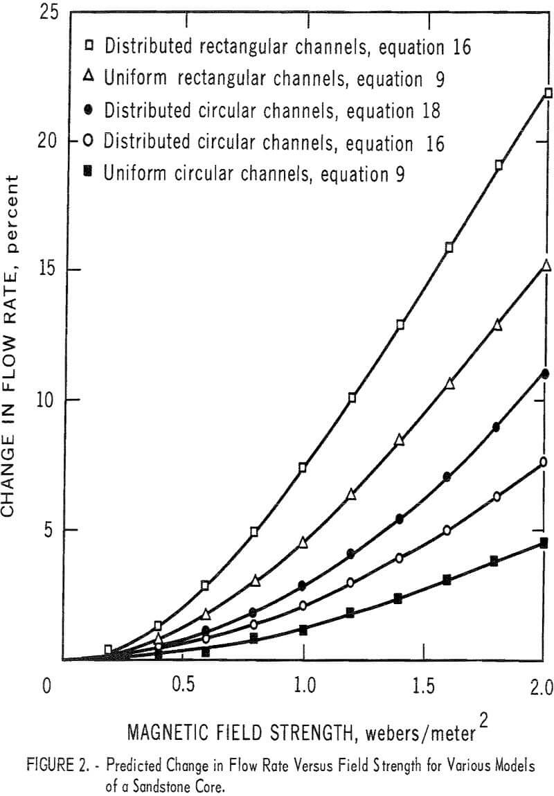
Figure 2 illustrates the application of these equations to one of the cores listed by Tignor. The data given for a Venango Second Sandstone reservoir core of Devonian age are n’ = 156.09 x 10 6, A1 = 0, and A2 = 10 -8m². The curves for distributed rectangular and distributed circular capillary models come from equations 16 and 18. The curves for nondistributed (single) rectangular and circular channel models come from equations 9 and 12, and the value used for the half-width and radius is that corresponding to the average pore size of A = 3.75 x 10 -9m² found from
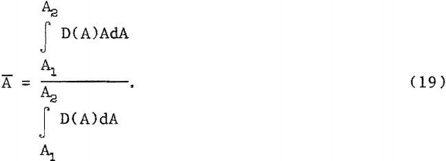
Since Shercliff’s equation is valid only for M <1, the curve from equation 18 is valid only to about B = 0.7; above this field strength the Hartmann number is greater than 1 for the largest channels in the model.
Equation 16 was evaluated by numerical integration techniques using a computer.
The hydromagnetic effect can be augmented by shorting the electrodes placed on the top and bottom of the channel. This can be shown in the theory to increase the current density J and thus increase the hydromagnetic retarding force. An extension of this concept is the electromagnetic pump in which, instead of merely shorting the two electrodes, an external source of voltage is placed between them. This can generate much higher currents in the fluid than those induced by the Lorentz voltage. The currents can, in fact, be reversed, which would lead to a pumping rather than a braking effect. Both Hartmann and Germeles have developed formulas to describe the electromagnetic pumping action. Any change in the flow rate due to crossed electric currents and magnetic fields can be interpreted in terms of an additional pressure head and does not depend on the Hartmann number.
The force on a filamentary current, Idl, in a magnetic field, B, is
![]()
If the current is uniform and passes in the x direction through the base of a clear channel of dimension 2a x h x L, then from this the pressure head developed in the channel in centimeters of mercury is

where p is the density of mercury and g is acceleration due to gravity.
Experimental Procedure and Results
A cylindrical Venango Third Sandstone sample and two rectangular porcelain samples were coated with a plastic adhesive and epoxy resin, except for the ends, and saturated with mercury. A sample was then secured between the pole faces of a magnet (fig. 3) so that the magnetic field was normal to the broad sides of the rectangular cores and normal to the axis of the cylindrical core, and the fluid flow was through the length of the core. The magnet, made from a transformer core, had pole faces approximately 12 sq cm in area and was
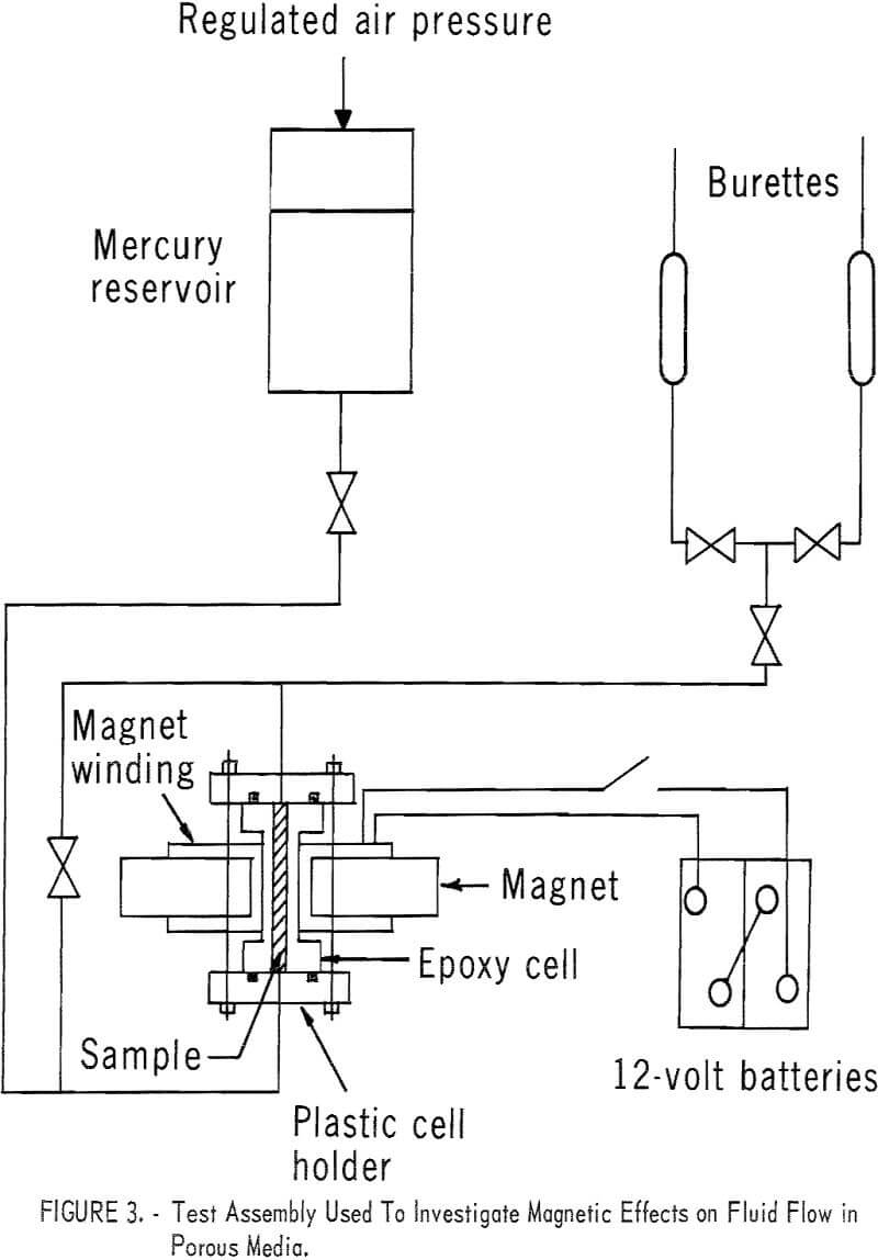
powered by two 12-volt batteries. The magnetic field strength was measured by a Hall effect gaussmeter.
The method of flow measurement consisted of timing the flow of a volume of mercury through the core between the reservoir and a burette or graduated cylinder. After the time had been recorded for flow with the field off, the mercury was returned to the original container and the same volume was used for flow with the field on. Under these conditions, hydromagnetic effects should appear as a change in the time required for flow of the specified volume.
The magnetic field did not produce a change in the flow rate of mercury. The lack of observable effect is an indication that the induced current in the mercury was too small to create an observable body force on the fluid.
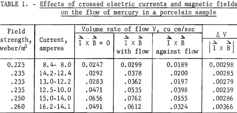
Experiments were therefore performed in which an external voltage was applied across the height of the core; that is, in a direction that would augment the internally induced currents. Changes in the flow rate were then readily observed. The results obtained from forcing a current through a porcelain sample perpendicular to the magnetic field are given in table 1. The average volume rate of flow produced per unit I x B was 0.00296 cu cm/sec. The sample had a porosity of 27 percent and an average pore radius of 25 microns.
Electromagnetic pressure heads were measured in the following manner: A small vertical tube was connected to each end of the cell, the cell was filled with mercury, and the equilibrium level of mercury in the two tubes was recorded. The current and the magnetic field were then turned on, which caused the mercury to rise in one tube and to fall in the other. The new equilibrium levels were recorded, and the difference in the two levels was the pressure head produced by the electromagnetic pumping effect. When the direction of the current was reversed, the rise and fall occurred in the opposite tubes. Table 2 lists the pressure heads produced across a porcelain sample and a clear channel. The average pressures produced per unit I x B were 0.0832 and 0.202 cm Hg for the clear channel and the porcelain sample, respectively.
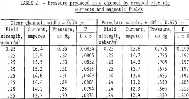
The clear channel was 0.74 cm wide. For 15 amperes of current and a magnetic field of 0.25 weber/m², equation 21 predicts that a pressure head of h = 0.37 cm Hg would be produced. Table 2 shows that the comparable pressure head measured was h = 0.31 cm. Thus, the calculated and experimental values match fairly well for a clear channel. The porcelain sample was 0.675 cm wide. For a clear channel of this width and the same current and field as previously, equation 21 predicts a pressure head of 0.51 cm Hg, However the comparable pressure head measured for the sample was about 0.75 cm Hg (table 2).
Discussion
Since no change in the flew rate of mercury through porous samples was observed on application of a transverse magnetic field of about 0.25 weber/m², it is believed that an effective channel half-width that would characterize the magnetic effect may not be much greater than the average pore radius. If this is true, then, on the basis of theory, field intensities in the neighborhood of 1 to 2 weber/m² would be required to produce readily observable changes in mercury flow rate in sandstone samples. From the curves of figure 2 it can be seen that an appreciable change in flow rate is indicated for all models at field intensities greater than about 1 weber/m².
It might seem that circular cross-sectional channels would make a more valid model than rectangular channels of high aspect ratio. However, the use of rectangular channels with high aspect ratio may not be unrealistic since the tortuous interconnection of the pores in the rock would offer a long path for the magnetically induced currents to follow.
It might be asked if the observed static pressure heads produced by the electromagnetic pump are consistent with the change in flow rate observed for flow in the crossed field and current. The average pressure head per unit I x B produced in the porcelain core was 0.202 cm Hg (table 2). This pressure head alone should produce a volume rate of flow per unit I x B of 0.00250 cu cm/sec. The average change in the flow rate per unit I x B is 0.00296 cu cm/sec (table 2). These two values show reasonable correlation.
Further experimental work is necessary to determine the generality of the result that larger electromagnetic pressure heads are obtained in a porous channel than in an open channel under conditions of equal current and field strength. The pressure heads developed in a porcelain sample are greater than those calculated for a clear channel of equal size, but no direct experimental verification was made. The clear channel used in the experiment had a slightly different width than the porcelain sample, but it is significant that, the calculated and observed values of pressure for the clear channel are in reasonable agreement.
If the difference is due to the increase in current density alone in the porous samples, then the ratio of the pressure heads for clear to filled channels should be equal to the porosity for the uniform capillary bundle model. The porosity of the porcelain core is 0.27, while the ratio of the pressure heads is 0.68. This lack of correlation suggests that the magnetic effect is influenced by pore geometry.
