Table of Contents
The Bureau of Mines has developed and tested countercurrent fluidized bed, multiple-compartment ion-exchange columns (MCIX) to recover uranium from mine water, clear solutions, and slime slurries. A 14-inch-diameter MCIX absorption column and a 4-inch-diameter fixed-bed upflow elution column were field tested on uranium-bearing mine water at Bingham Canyon, Utah, and Grants, N. Mex. The same system was tested on alkaline leach slurry at Moab, Utah. A 6-foot-diameter column was hydraulically tested in Salt Lake City, Utah. A 20-inch diameter absorption column was tested on acid leach slurry at Edgemont, S. Dak. Laboratory testing with a 2-inch-diameter column showed that it was feasible to use a compartmented column for countercurrent elution, which allows a higher throughput than was possible with a fixed bed.
Previous cost estimates indicated considerable savings over conventional resin-in-pulp (RIP) basket-type operations because the resin requirement for the compartmented columns was determined to be about 35 percent of the amount needed by basket-type RIP circuits of the same throughput capacity. Based on 1972 costs and milling 2,000 tons of ore per day, it was determined that the capital required for the countercurrent ion-exchange plant was 73 percent of the amount for a solvent-extraction plant and the operating costs for the ion-exchange plant were 81 percent of the solvent extraction planter.
MCIX columns are in commercial use for gold recovery from cyanide solutions using coarse activated, carbon particles, and prototype columns are in use for uranium absorption and elution.
During the past year, the Bureau of Mines has conducted additional studies to better quantify the design criteria for multiple-compartment ion-exchange columns. The initial phase of the investigations discussed in this paper involved the use of 1-inch- and 2-inch-diameter columns. These columns were improved modifications of earlier designs; more precise flow control and sequential timing instrumentation were added to obtain ‘better reproducibility and operational continuity. Both individual and integrated absorption-elation circuit arrangements were used during this work.
Equipment
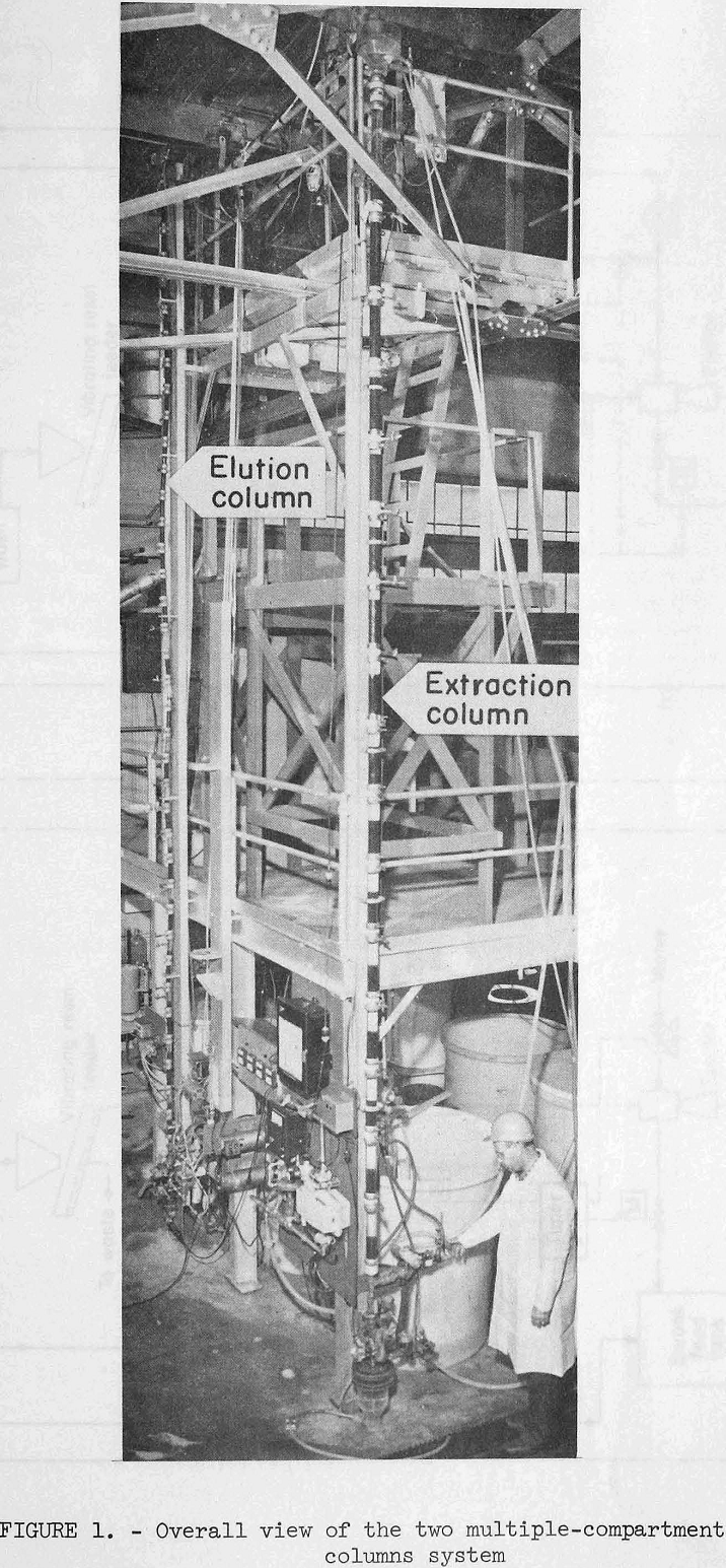
The main component of the absorption equipment used in the current experimental program was a 2-inch-ID by 16-foot-high glass column composed of 1-foot sections as shown in figure 1. The main component of the elution circuit was a 1-inch-ID by 22-foot-high glass column composed of 6-inch sections. A detailed flowsheet of the circuit is shown in figure 2, individual compartments were separated by orifice plates that had openings equivalent to approximately 6 percent of the column cross-sectional area. The columns were constructed so that the compartment height could be modified by substituting full diameter couplings for the orifice plate couplings. Rosenbaum and Ross state the following about the use of these orifice plates.
“Observation has shown that when a regulated flow of solution passes upward through a column of closely sized resin at a rate sufficient to fluidize the resin, vertical mixing occurs over the length of the column. In effect, the entire column serves as a gently agitated reactor and, under these conditions, equilibrium stringently limits the absorption kinetics and efficiency. By assembling the resin column out of short segments, each separated by a perforated plate, vertical mixing still occurs within each segment of expanded-bed resin, but the net overall effect is of multiple-stage absorption or elution yielding more rapid and complete ion transfer than obtainable in a noncompartmented column of equivalent height.
Under ideal operating conditions, each compartment is nearly full of fluidized resin in equilibrium with the upflowing solution. If the quantity of resin in any compartment is initially in excess of the equilibrium volume, the excess resin moves up through the perforated plate into the next compartment. If the quantity of resin is less than the equilibrium volume, the compartment will not be completely filled. Downward movement of resin between compartments can occur only when the velocity of the solution flow through the holes in the perforated plates is less than the terminal settling velocity of the resin particles. An increase in solution flow rate or density will cause the resin bed to expand. When using coarse bead resins, minus 16- plus 20- mesh perforated plates that have an open area of approximately 5 percent are satisfactory.”
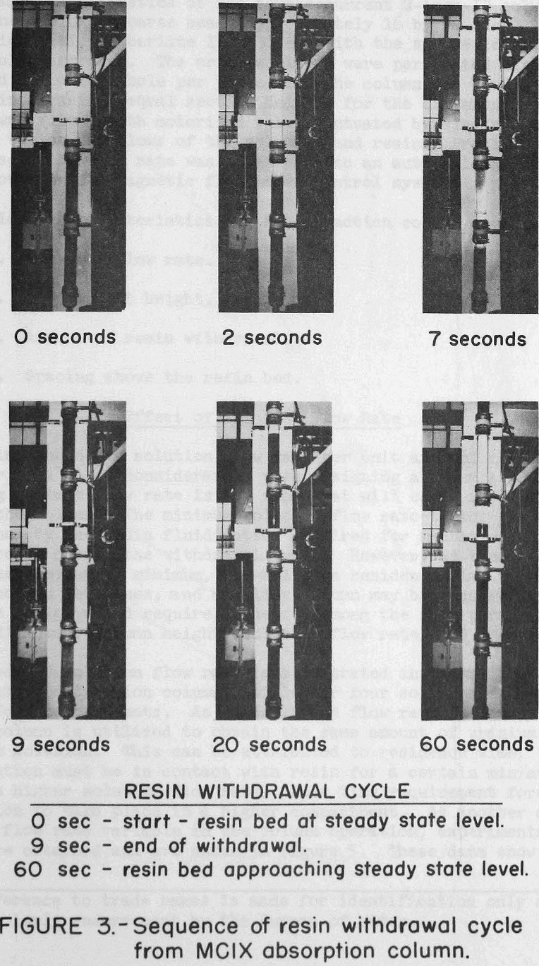
The column is operated with a continuous upflow of solution except for the scheduled resin withdrawals. During these resin withdrawals, the automatic solution inlet valve closes, and the automatic resin outlet valve opens to discharge a programmed amount of resin from the column. The discharge periods are approximately 6 to 12 seconds for the absorption column and 3 to 6 seconds for the elution column. The time
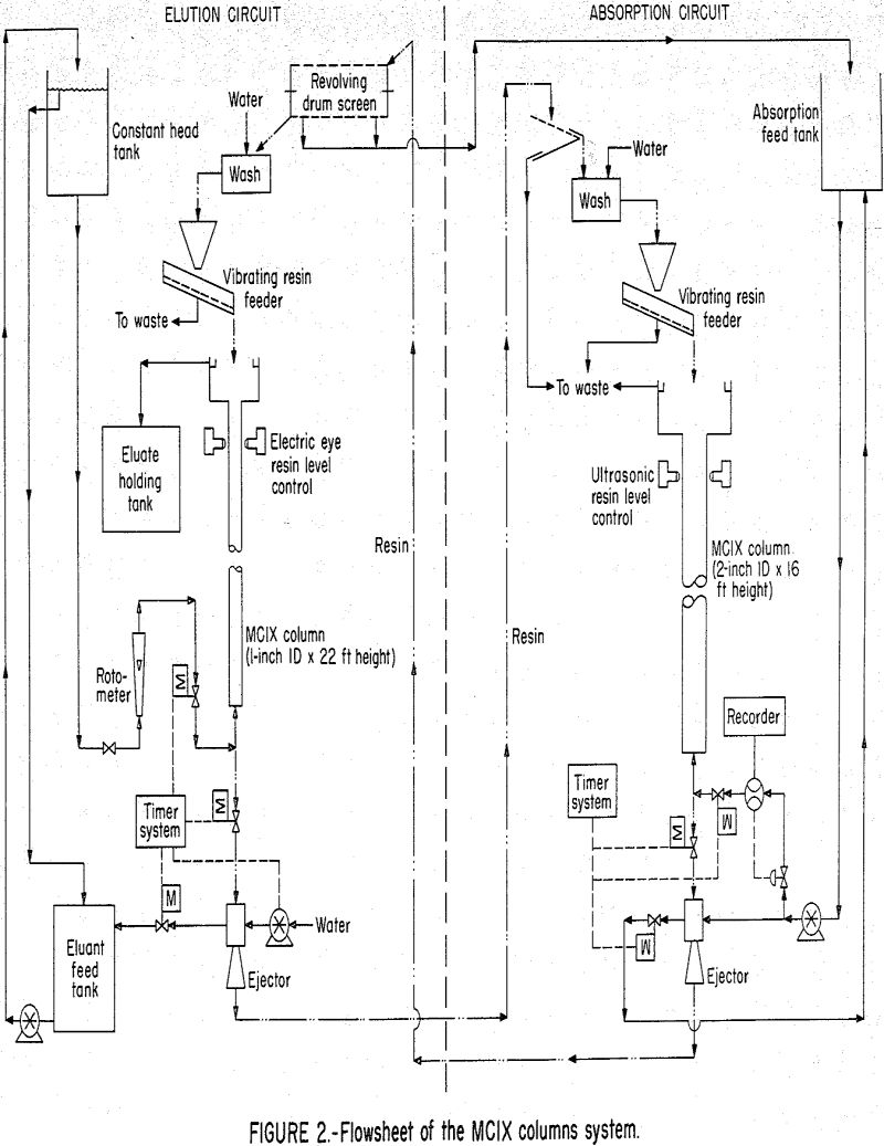
interval between withdrawals from the absorption column is determined by the amount of resin to be discharged per withdrawal cycle, and this is a function of feed solution flow rate, feed solution concentration, and desired resin loading. The actual time during which the resin discharge valve must be open to discharge a programmed amount of resin is a function of the valve opening configuration and the bed expansion. During column operation, the solution flows were controlled by automatic instruments; and the open time interval on the resin discharge valve was set by trial and error adjustments. Figure 3 shows a pictorial sequence for one cycle of the resin discharge operation. The 4-foot compartment shown in this figure is made up of 1-foot glass sections and full diameter couplings.
The solution flow rate controllers are a critical component of the system. Previous work did not have the precise flow rate control necessary to assure steady-state operation. Without this control, the resin migrates from one compartment, to another at random, and the column conditions remain transient. To control solution flow to the extraction column, an automatic system was used which consisted of a magnetic flowrator, a controller, and an air diaphragm valve. This system had a precision within ±1 percent of the maximum flow rate through the magnetic flowrator. For controlling the relatively low flow rates to the elution column, a constant head tank and rotameter were used.
Solution Description
The absorption column feed solution used for these tests simulated the composition of a uranium leach liquor typical of that in a Wyoming mill processing Shirley Basin ore. The composition and pH of this clear, simulated mill solution are listed in table 1. Both absorption and the subsequent elution were conducted at room temperature.

The eluant was a 1.5 M NaCl solution acidified to pH 1.0 with H2SO4 commonly used by industry.
Extraction Column Tests
Operating characteristics of the countercurrent 2-inch-ID column were determined using a coarse bead (approximately 16 by 20 mesh) strong-base anion resin (Amberlite IRA 430) with the synthetic mill solution previously described. The orifice plates were perforated with one centered 29/64 inch hole per plate, and the column was divided by these plates into various equal section heights for the different tests. The column was fitted with motorized valves actuated by electric timers to control the on-off flows of the solution and resin. Precision control of the solution flow rate was obtained with an automatic air diaphragm valve coupled to a magnetic flow meter control system.
The following characteristics of the extraction column were studied:
- Solution flow rate.
- Compartment height.
- Amount of resin withdrawal.
- Spacing above the resin bed.
Effect of Solution Flow Rate
The optimum economic solution flow rate per unit area of column diameter is a major consideration when designing a column system. The limiting maximum flow rate is the flow that will carry resin from the top of the column. The minimum solution flow rate to the column is determined by the resin fluidization required for mechanical transfer of the resin during the withdrawal cycle. However, as the flow rate increases above this minimum, the solution residence time per foot of column height decreases, and a taller column may be required. Optimum economic design would require tradeoffs among the four parameters of column diameter, column height, solution flow rate, and uranium recovery.
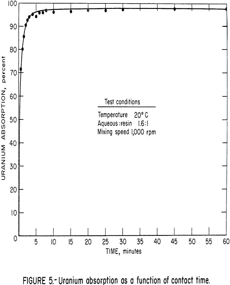
The effect of solution flow rate is illustrated in figure 4, which shows the solution extraction column profile for four solution flow rates with 1-foot compartments. As the solution flow rate increases, more of the column is utilized to obtain the same amount of uranium extraction from the solution. This can be attributed to residence time, i.e., the solution must be in contact with resin for a certain minimum time, and with higher solution flow rates, this time requirement forces the extraction to take place in a higher compartment. As another approach to this flow rate variable in the column operation, experimental kinetic data were obtained and are shown in figure 5. These data show a very

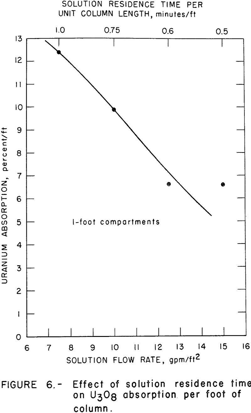
fast rate of uranium absorption over the first few minutes of contact. Therefore, changes in solution residence time per compartment within this time range would have tremendous impact on absorption attained in that compartment. Figure 6 shows the average U3O8 absorption as a function of solution flow rate and solution residence time. This figure illustrates that the absorption of uranium decreases with decreasing solution residence time as would be predicted by the kinetic data of figure 5. Therefore, for a column height similar to the one tested (16 feet with 1-foot compartments) a solution flow rate of about 10 gpm/ft² appears optimum for a feed solution containing about 1 gram of U3O8 per liter.
Effect of Compartment Height
The multiple-compartment column can be considered as an assemblage of agitated stages in which extraction is achieved by a series of mass transfers from the solution to the resin. To be effective, the column must provide the required number of transfer stages, each having sufficient solution retention time for a reasonable approach to equilibrium mass transfer. As discussed in the previous sections, the solution retention time is critical because the transfer of uranium from the solution to the resin sites is not instantaneous.
The stage height is of particular consequence because it can affect both the column construction cost and the inventory of resin required to fill the column.
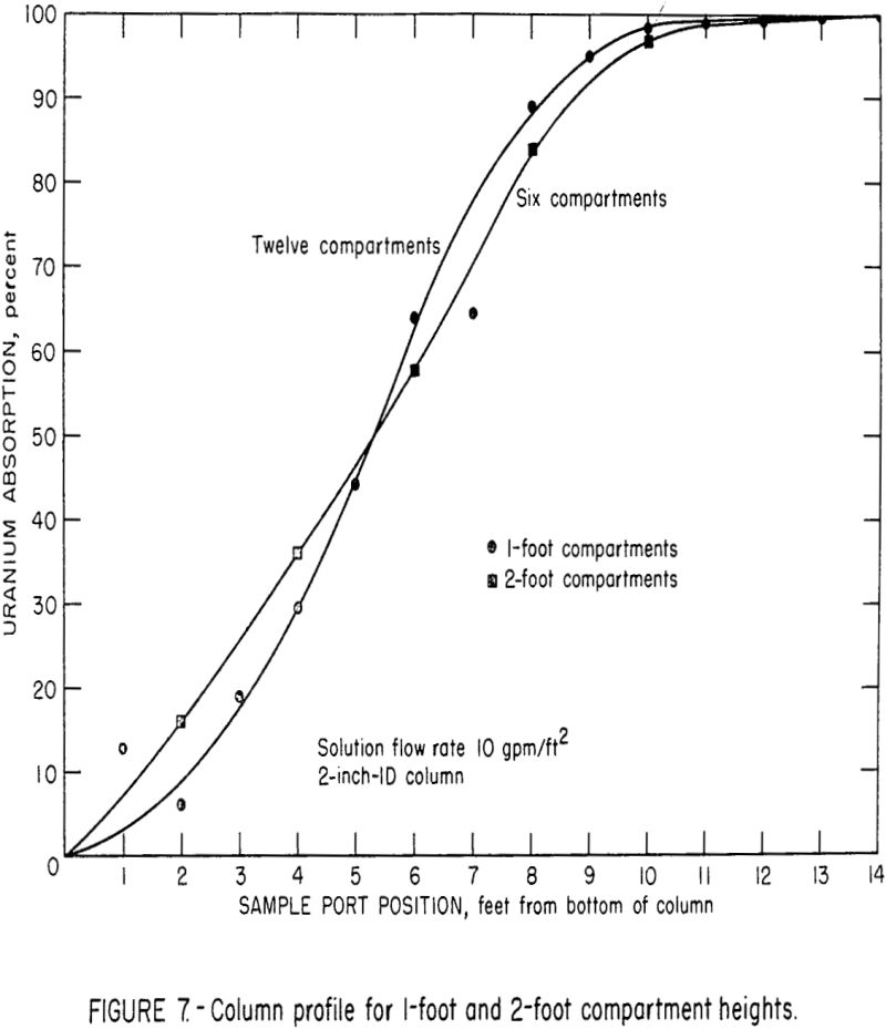
Studies are being made to determine the effect of compartment height on column efficiency; part of this work has been completed. Figure 7 illustrates the uranium extraction profile of the 2-inch extraction column when operating with 1-foot compartments and 2-foot compartments. The solution flow rate was 10 gpm/ft², and the solution-to-resin throughput ratio was approximately 60:1. These curves indicated that the mass transfer of uranium per foot of column height was essentially the same for both the 1-foot and 2-foot compartment heights. Apparently, there was a tradeoff between the effects of solution residence time per stage and the number of stages in the total column. Tests were also made using 4-foot compartment heights, but observations and indirect evaluations indicated that the degree of mixing in the 4-foot height was significantly less than those in the 1-foot and 2-foot compartments. This change was probably the result of the increased wall effects produced by the 4-foot compartments. The resin classified in these relatively long, narrow compartments, and a favorable chromatographic loading effect was obtained. This effect produced loadings that were significantly greater than the theoretical loading that can be obtained in a mixed stage. Subsequent observations of the mixing in a 6-inch-diameter by 4-foot-deep resin bed indicated that the up and down movement of resin in this column was considerably greater than in the 2-inch diameter column. This inconsistent mixing in the 2-inch-diameter column precludes comparison of data from the 4-foot sections with that from the 1-foot and 2-foot sections.
It is possible that some favorable resin classification may take place in larger diameter columns, but additional tests will be required to substantiate this relationship.
In general the current data indicate that compartment heights from about 1 foot to 2 feet will produce approximately the same absorption efficiency for a given column height. It is also possible that this uniform efficiency may extend to 4-foot compartment heights.
Effect of Amount of Resin Withdrawal
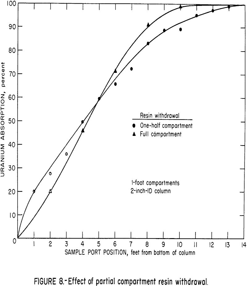
For the 2-inch-ID column used in these tests, the withdrawal and transfer of resin could be done very efficiently within a short interval of 3 to 15 seconds. It was possible, therefore, to withdraw any desired fraction of the resin from one compartment with a minimum of handling problems and interruption of column feed. However, in a large column where the resin in one compartment constitutes a substantial volume, the withdrawal and more particularly, the screening, washing, and transferring of resin from an entire compartment would present mechanical handling difficulties. An operational cycle with partial withdrawal would minimize this difficulty. Tests were run to evaluate the effect of this partial section withdrawal. With the resin becoming more dense as it becomes loaded with uranium, the upward flow of solution tends to classify the more heavily loaded resin beads at the bottom of each section. Therefore, in half-section withdrawals the heaviest resin is always withdrawn. The comparison of column profiles for a fall-section resin withdrawal and a half-section resin withdrawal is shown in figure 8. The results indicate no significant difference between the two resin withdrawal methods.
Spacing Above the Resin Bed
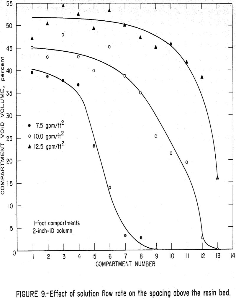
During the normal operation of the absorption column, eluted resin is fed into the top compartment of the absorption column and the resin level is maintained by an automatic controller. The eluted resin is the lightest resin in the column and, therefore, the resin bed in this top compartment is the most expanded bed in the column. As a resin increment is withdrawn from the bottom of the column, the resin in the rest of the column compartments moves down. When steady-state operation has been achieved, only a fixed amount of resin is transferred from compartment to compartment during each discharge cycle. As the resin in each individual compartment absorbs the uranium from the solution passing through that compartment, the density of the resin beads increases causing less bed expansion in that compartment. This decrease in bed expansion coupled with the transfer of equal numbers of resin beads gives rise to empty spaces above the resin in the compartments below the top compartment. Solution density changes are considered negligible (max. 0.15 percent).
The spacing as a function of stage number is shown in figure 9 for various solution flow rates. Increasing the solution flow rate stretches the working length of the column. In other words, for 7.5 gpm/ft², as shown previously in figure 4, the loading is complete in the first 8 or 9 feet of the column; and therefore, the density change occurs in those compartments. Above those compartments, no uranium is available to be loaded, therefore, no density changes take place. In contrast, loading occurs principally in the upper part of the column at the 12.5 gpm/ft² flow rate; and therefore, most of the density change also occurs in the upper compartments.
Elution Column Tests
Elution studies were made to expand previous information and to develop a better understanding of the flow-rate and stage-effect variables. The elution of the resin was carried out in both a countercurrent 2-inch-ID MCIX column and a countercurrent 1-inch-ID MCIX column using the 1.5 M NaCl eluant previously described. The resin feed was a loaded coarse-bead strong-base anion resin containing 40 to 50 grams of U3O8 per liter of wet settled resin (WSR). In the 2-inch-ID column, the orifice plates were perforated with one centered 29/64-inch hole per plate; in the 1-inch-ID column, the orifice plates were perforated with one centered ¼-inch hole per plate. Again the column was fitted with motorized valves actuated by electric timers to control the on-off flow of the solution and resin. Solution flow rate was controlled by a rotameter and constant head tank.
Satisfactory elution was obtained in both the 2-inch and 1-inch columns, but data scatter limits the comprehensive design conclusions that can be made at this time. However, it seems there is a minimum residence time, determined by the solution flow rate and column diameter, that is required to elute the resin properly. We found the approximate range of this variable to be about 2 to 5 gpm/ft² for a 20-foot-high column with 18 to 36 sections (approximately 180 to 270 minutes of resin residence time and 30 to 50 minutes of solution residence time). The degree of resin fluidization in the elution column is less than that of the absorption column owing to the decreased solution flow rate, but the fluidization is still above the minimum required for mechanical resin transfer.
The aqueous-to-resin flow ratio (A:R) influences both the degree of elution and the eluate grade. There appears to be a minimum A:R ratio of approximately 4 for good elution. This requirement is the result of chemical and mechanical constraints on column operation. The A:R ratio would have to be optimized for each application of the column. A well-eluted resin (<8 g/l U3O8) is required to obtain a low effluent value in the absorption circuit, whereas a high-grade eluate (10 to 25 g/l U3O8) is desirable for subsequent uranium precipitation.
Another point would be that the separation into stages is critically-important in the elution cycle. Contrary to the absorption cycle where the density changes are favorable, the reverse is true in the elution circuit. Loaded resin, which is the highest density resin, is transferred from the bottom of the absorption column to the top of the elution column. As the resin moves down through this column, it is eluted, and its density decreases thereby increasing its bed expansion. This bed expansion would cause the lighter resin beads to be pushed into the next higher compartment, which contains denser resin beads. “This trend would continue and top-to-bottom mixing (heavy loaded beads to the bottom and eluted beads to the top) would occur and be detrimental to the elution operation. The density change of the solution is considered to be negligible (max. 2.8 percent). Also, exact full resin withdrawals would be very important in elution. Fractional resin withdrawals would continually draw out the heavy or more loaded resin in the bottom compartment leaving more eluted resin in the column.
Summary
This initial phase of the design investigations on the multiple-compartment, integrated, ion-exchange columns has provided a range of operating parameters for the system. For the absorption circuit with a 16-foot-tall column and 1- or 2-foot-high compartments, a solution flow rate of 10 gpm/ft² was optimum.
A solution flow rate of 2 to 3 gpm/ft² gave satisfactory elution in a column containing 18 1-foot compartments. Eluate grades of 10 to 20 g/l of U3O8 were obtained.
Additional investigations are in progress to obtain data for developing a mathematical design model for the MCIX column system. Particular attention will be paid to mixing effects in individual compartments.
