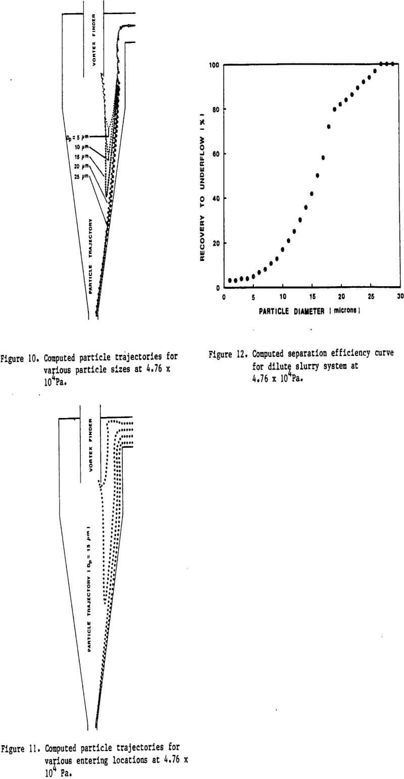
Mineral and chemical industries use the hydrocyclone for size classification as well as solid-liquid separation. The geometry of the device being very simple, a tangential involute section attached to a cylindrical section and a conical section attached to the other end of the cylinder, the device has found widespread use. Majority of the research papers dealing with the modeling of the hydrocyclone have correlated with size classification produced by the unit as a function of inlet slurry parameters and dimensions of the unit. Essentially such empirical approaches treat the body of the hydrocyclone as a black-box and try to correlate input and output variables by suitable expressions. The objective of this paper is to model the hydrocyclone from a mechanistic point of view. When a fluid containing particles is injected into the device centrifugal forces are created as the slurry spins in the device. The conical section converts parts of the downward directed momentum into upward momentum and radially directed momentum. The exchange of inlet momentum into momenta in the component directions can be described with the well known Navier-Stokes equation. Essentially, the velocity components in the radial, axial and tangential directions can be solved for, knowing the geometry of the device and inlet Reynolds number. Further, by balancing the forces acting on a particle one can arrive at the slip velocities between particle and fluid, and consequently the trajectory of every particle within the body of the device. Simply by following the path of the particle from the inlet to either the overflow stream or underflow stream the size classification curves can be computed. Such a phenomenological approach offers the facility for examining the influence of hydrocyclone geometry on size classification which was impossible with empirical models.
Experimental
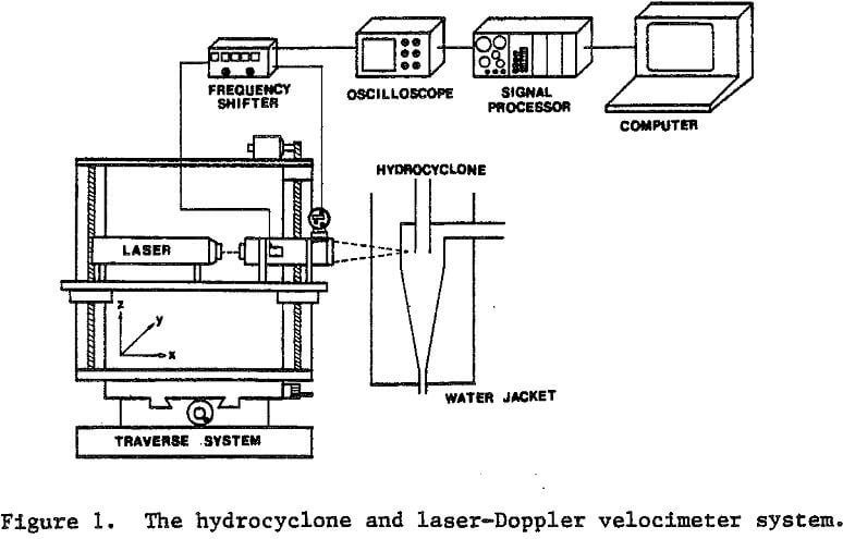
A single-channel 35 mW He-Ne laser Doppler velocimeter (LDV, TSI model) is affixed to a three-dimensional traverse system (Fig. 1) to measure velocity profiles. The precision of the traverse system is 0.01 mm. Backscatter alignment was used in the experiments because of the presence of the air core, which diffuses the laser beam as it passes through the gas-liquid interface. A frequency shifter connected to the LDV system permits detection of the flow direction as well as the measurement of low-velocity flow.
Results
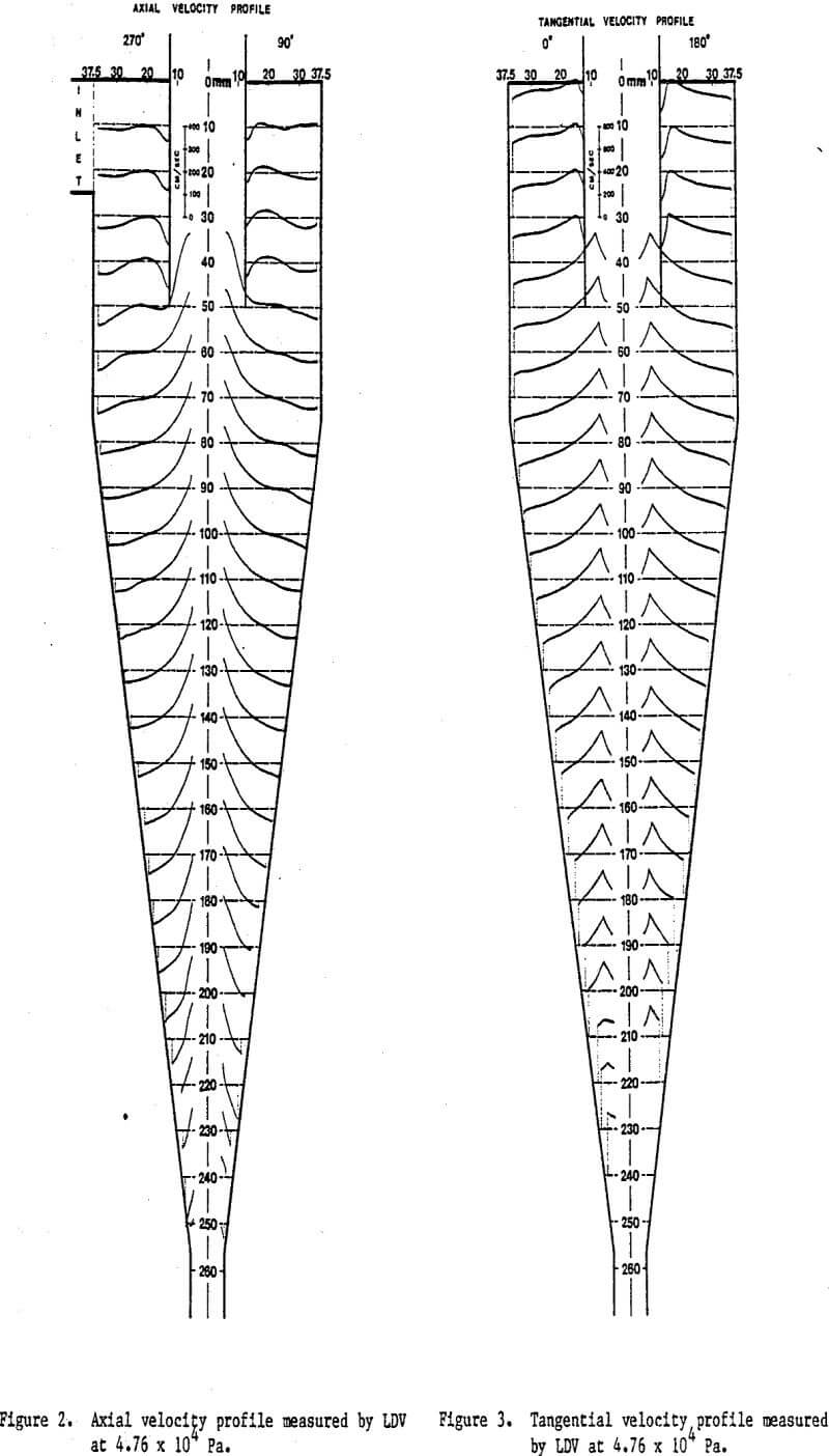
Experimental velocity measurements by LDV open up a wealth of information about the hydrocyclone. Figure 2 shows the axial velocity measurements at two different angles; the profiles are asymmetric about the vertical axis in the vortex-finder region, because the inlet flow enters on one side of the vertical axis only. This asymmetry is predominant near the region where the inlet flow enters and gradually becomes almost symmetric below the vortex finder. However, asymmetry appears again in the vicinity of the apex since the fluid-flow passage narrows, giving rise to higher turbulence which in turn causes the air core to fluctuate. Interestingly enough, there is more than one reversal in flow direction in the region between the vortex finder and the wall, this observation is contrary to the commonly held belief that there is a single envelope that separates upward-directed flow in the central region from the downward-directed flow near the wall. When the feed enters the hydrocyclone tangentially, the linear momentum of the inlet flow converts to rotational momentum, and the main stream is flowing toward the apex. As the stream enters the conical portion, a central upward flow is introduced because of the geometry of the hydrocyclone.