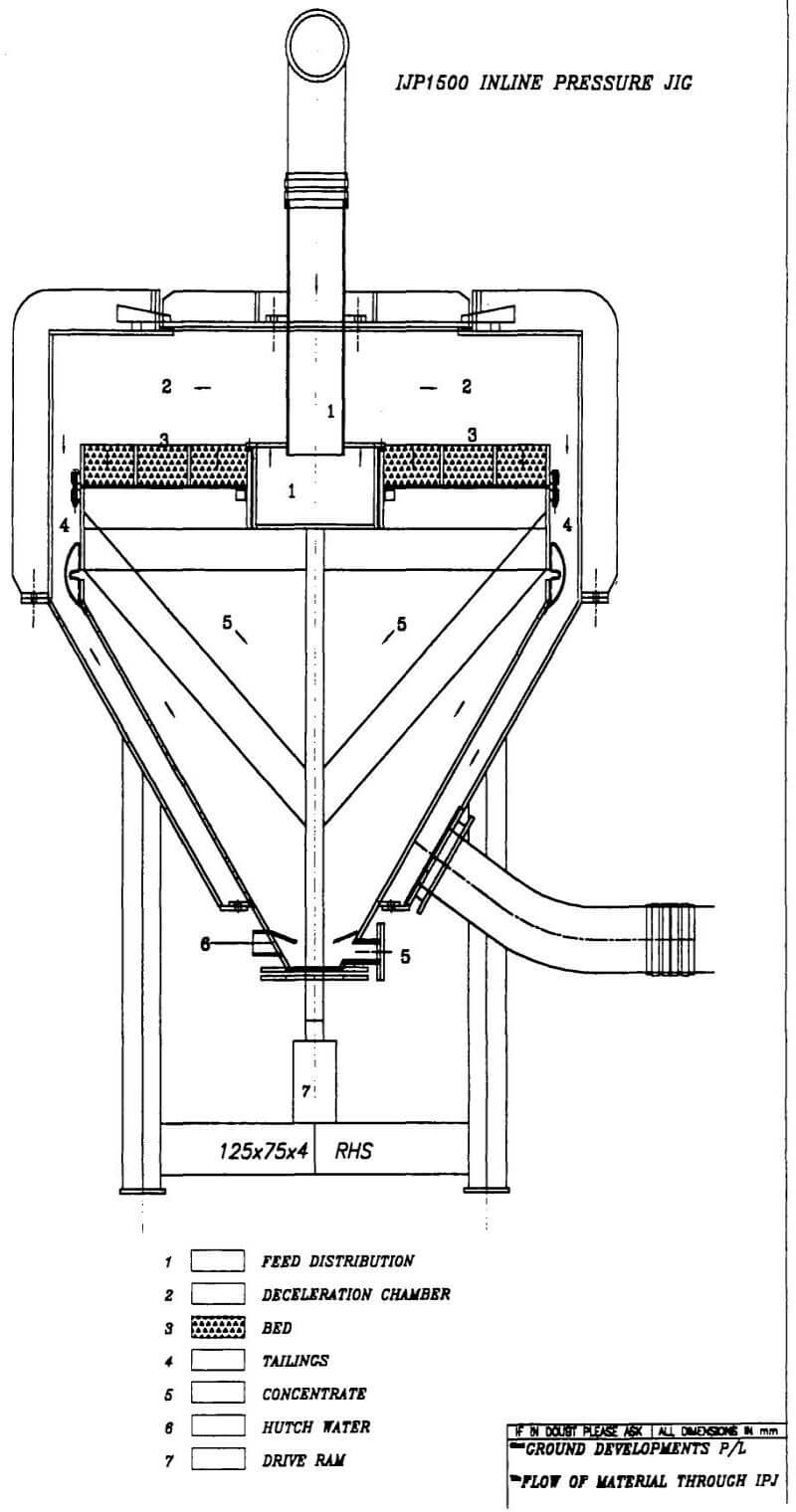
 Figure 1. Flow of material through Inline Pressure Jig. The feed is introduced through the feed pipe and distributor 1. The feed slurry is turned around in the distributor and flows out into area 2. which is called deceleration chamber. Due to the large volume of the deceleration chamber the flow rate drops below a velocity capable of supporting the suspended solid. The heavies drop to the bed 3 and are captured in the slow flowing material in the separation interface on top of the bed. The bed is pulsed through the central drive shaft by the drive ram 7 at the base of the machine. The heavies are pulsed and drawn through the bed into the hutch 5 where they report to the hutch outlet 5. The lighter material flows to the outer circumference of the bed and overflows the screen support frame to report to the tailings launder 4 hutch water addition is added through inlet 6 to provide concentrate water and pulse water through the screen.
Recoveries of Centrifugal Concentrators
It is often said that whilst the recovery efficiency of the BCC is not high the number of times which preferential recovery of gold to the circulating load re-presents the gold to the BCC allows it to eventually recover it.
The recovery method could be aimed at fine rather than coarse particles, as coarse particles will be recycled and can be recovered as finer fragments. The fine classification of gold also means that recycled streams should contain a significant amount of liberated gold in the range of 15 to 50 um; equipment that cannot recover gold in this size range is clearly sub optimal.”
However it is our contention that it could be equally stated that equipment that does not have high recoveries at coarse size ranges will provide sub optimal outcomes as coarse free gold may leave the circulating through the COF.
In virtually all of the studies reviewed by the author on gravity separation with BCC there has been no work undertaken on the amount of coarse liberated gold allowed to report to the cyclone overflow (COF). It is our contention that all coarse free gold down to 75 um does not preferentially report to the cyclone underflow (CUF).
Coarse free gold in COF
A survey carried out show COF trash screen oversize assays of up to 200 ppm. This is an example of coarse gold leaving the circulating load. Coarse free gold was visible in this product.
Factors that contribute to these losses of coarse gold to the COF are;
- High density in COF
- High viscosity
- High specific gravity of recirculating load.
- Coarse product in cyclone feed.
- Circuit upsets.
- Worn cyclones.
- Coarse cut points.
- Low pressure feed
Mineralogy carried out on leach feed indicate that Free gold was detected as rough craggy to flakey grains ranging from 10 um up to 200 um across. This circuit incorporates two 76 cm BCC’s operating 60 minute cycles. The free gold was not leached due to an external coating and reported to the tail. These findings show the importance of recovering the gold in the primary gravity circuit.
Retention Time and Trajectory
High density particles such as iron etc. which settle in the bed are accelerated to high velocity within the bed in the case of a 76 cm centrifugal concentrator, particles encounter a 60 g-force at the top ring. The incoming feed particles start with zero g-force exerted on them. The iron particles which are caught in the bed and are rotating with the bed have an induced specific gravity in excess of 300 whereas the free gold particles entering the concentrator have a specific gravity of approx. 18.
The projected trajectory of the particles in the feed will take the particle through about 0.6 revolutions of the bowl with a retention time of around 250 milliseconds. In reality the new feed particles are at a massive disadvantage to those rotating with the bowl as evidence by Laplante (1993) who states that centrifugal separation processes heavily depend on strong density differences which may limit the types of separation possible. The loss of recovery at the finer size ranges also indicates that finer particles never come in contact with the bed in order for the collisions (acceleration) to occur.
If the bed where truly fluidised and replacement process were to take place then the iron buildup in the bed would be replaced by gold. If the iron and gold were both competing in a fluidised bed at 60 g the relative specific gravity of the iron would be 300 and the gold would be 1080. Even taking into account differences in particle shape and size the separation should be extremely easy. However, this is not the case.
Particle separations have been achieved down to 40 um in the Inline Pressure Jig at 1 g. These separations appear to be affected by the same changes in conditions such as density and particle size as that of the centrifugal concentrator. It does not appear necessary to accelerate these particles to such high g-forces to achieve good results.
The retention time and cross flow velocity in the Inline Pressure Jig is the controlling factor for separation efficiency. The average retention time for any particle in the Inline Pressure Jig at rated capacity is about 12 seconds. This however is not true for the heavy particles which settle to the top of the bed and drag in the higher density separation zone. The bed area of the Inline Pressure Jig grades from virtually clear water on top to high density solids at the separation interface. The higher density zone travels at a lower velocity than that of the higher layers.
Separation efficiency is best when the environment is such that heavy minerals can settle to the higher density zone. Due to the flow dynamics of the Inline Pressure Jig the average flow velocity drops to the outer diameter of the unit. Turbulence also reduces further from the feed distributor. All of these factors enhance the recovery efficiency of the Inline Pressure Jig .
From evidence at hand it appears that the recovery of coarse gold in centrifugal concentrators can be poor. The combination of the Inline Pressure Jig and a centrifugal concentrator would be optimal in circuits where coarse liberated gold exists.
Inline Pressure Jig Recoveries
The InLine Pressure Jig is suited to the recovery of +40 micrometer free gold in grinding circuits. This statement is supported by the following data set collected from several sites. Each site was configured as a commercial installation operating in excess of 30 tph.

The use of gravity separation in decreasing operating costs and increasing recoveries in the hard rock gold grinding circuits will play an increasing role. The availability of new technologies will broaden the selection of equipment for the specific applications to maximise recoveries. For deposits with coarse gold and high grade spikes the application of the IPJ cannot be overlooked with its low cost, low water consumption and simplicity. In the case of deposits with a wide size distribution of gold a combination of devices will probably offer the best solution with the highest possible recovery outcome. The use of the IPJ in the grinding circuit to continuously recover a high grade concentrate offers flexibility at high recoveries. The Batch Centrifugal Concentrator is restricted in its overall recovery potential by its high upgrade ratio although its potential to recover fine gold (less than 45 micrometers) is greater than that of the IPJ. The combination of an IPJ in front of the BCC may well offer many advantages to both units. The IPJ would recover the coarse gold and heavies from the BCC feed with a resultant reduction in feed specific gravity thus improving performance.

