Table of Contents
This Bureau of Mines investigation was prompted by the need for a stable anode for electrowinning metals, particularly zinc and copper, from acid solutions. The polarization behavior of Pb-Ag (1 pct Ag) anodes in H2SO4 and fluoride solutions was determined as the first step in the development of such an anode. A Luggin capillary, DC power supply, high-impedance voltmeter, and other equipment standard to an electrochemical laboratory were used in this study. It was determined that during polarization, a relatively hard, stable coating of PbO2 was formed on the surface of the lead-silver anode and the rate of formation of this coating was considerably enhanced by the presence of fluoride ions in solution.
Subsequent investigations at the Bureau of Mines Rolla Research Center resulted in the development of a PbO2-coated titanium (PbO2-Ti) anode. Results of this effort were presented in Bureau of Mines Report of Investigations 8111.
Additional data resulting from extensive testing of the PbO2-Ti anodes, as well as process improvements and innovations, are included in this report. The anodes were considered generally unsatisfactory for zinc electrowinning because of lower conductivity, higher oxygen overvoltages, and shorter in-cell life as compared with the Pb-Ag anodes now being used in industry. However, the PbO2-Ti anodes were used successfully to oxidize waste chromium solutions and to electrowin copper.
One of the major problems associated with the aqueous electrowinning of metals is the selection and maintenance of a suitable anode. There are a number of desirable characteristics that the anode should possess, and these involve both technical and economic factors:
- Inertness or moderately good corrosion resistance to the electrolyte,
- favorable polarization behavior with a low overvoltage for the oxidation reaction involved,
- minimum contamination of the cathode metal from decomposition or reaction products,
- good electrical, physical, and mechanical properties,
- and low capital cost.
Lead has been found to be applicable for many nonferrous electrolytic processes and, as a basic starting material, provides a system that possesses most of the above mentioned requirements. Lead is not satisfactory, however, unless certain technical criteria can be met, one of which is the presence of a stable PbO2 coating.
The work of Razina indicated that initially a PbO2 anode was 10 times more stable in H2SO4 solutions than an ordinary Pb-Ag anode under the same conditions. Therefore, attention focused on PbO2 anodes as offering the best possibilities for stability in electrowinning, and specific studies were directed toward zinc electrowinning.
One of the most significant milestones in improving the electrolytic zinc process occurred about 1930 with the development of Pb-Ag anodes by Tainton, Hanley, and others. Pure lead anodes were used for electrowinning zinc in the beginning; however, they dissolved extensively at the current densities and temperatures encountered in zinc electrolysis. Contamination of the zinc deposit and the valuable manganese dioxide byproduct in the anode slime resulted. The amount of corrosion encountered with the alloyed anodes was considerably less than that for pure lead, which allowed purer zinc to be obtained. The optimum concentration of silver, based on performance and economy, was adjudged to be 1 wt-pct.
Lander postulated that silver acts as a depolarizer according to the following reactions:
PbSO4 + 2H2O = PbO2 + SO4= + 4H+ + 2e-, E° = +1.685 v…………………..(1)
Ag+ = Ag++ + e-, E° = +1.980 v…………………………..(2)
where E° = standard electrode potential. Reaction 1 takes place at the Pb-Ag anode during electrolysis. As the reaction nears completion, the evolution of oxygen commences and, at the same time, the anode potential becomes more positive to an extent that reaction 2 occurs. If reaction 2 occurs, Ag++ can oxidize water to H2O2 as in reaction 3,
2H2O + 2Ag++ = H2O2 + 2Ag+ + 2H+, ∆G° = -9.5 kcal…………………………….(3)
and H2O2 decomposes in acid solution to give oxygen,
2H2O2 = O2 + 2H2O, ∆G° = -50.4 kcal,………………………………………(4)
where ∆G° = standard free-energy change. Thus, the effect of silver is to supply an alternate path for the evolution of oxygen, which would result in a decreased oxygen overvoltage and a reduction in anode corrosion under constant current conditions. The same mechanism can be postulated to explain the effects of cobalt in solution during zinc electrolysis.
The use of Pb-Ag anodes markedly reduced the rate of anode corrosion and the amount of lead subsequently entrapped in the cathode during zinc electrowinning, however, problems with contamination of the cathode with lead continued to exist. Lead in zinc at levels greater than 30 ppm makes the zinc metal unsuitable for die-casting applications because of problems associated with intergranular corrosion.
An overwhelming amount of evidence presented to date indicates that contamination of the zinc cathode with lead is the result of loosely adherent films of PbSO4 that are detached from the anode during electrolysis, and the insoluble PbSO4 is subsequently trapped in the deposited metal at the cathode. Therefore, to understand the problem of lead contamination of cathode zinc, one must understand the mechanism of PbSO4 formation at the anode.
At the beginning of electrolysis with a lead or lead alloy anode in a sulfate electrolyte, Pb++ ions from the dissolution of the anode react with SO4 ions and PbSO4 precipitates on the surface of the anode. Since PbSO4 is a dielectric, the voltage rises and in the range of 900 to 1,200 mv (potential versus the Hg-Hg SO4 reference electrode, -0.667 v), a stable conductive film of α-PbO2 is formed. At potentials greater than 1,200 mv, β-PbO2 is the predominant phase. Conditioning times of from a few hours up to several months are necessary before a completely stable PbO2 coating is formed and a pseudoequilibrium is established. Cathode deposits containing lead that are produced during the conditioning period are often unsatisfactory for sale.
If for any reason power to the cell is discontinued, either during the conditioning process or after a stable coating of PbO2 is formed, the deposition process is reversed and PbSO4 crystals form on the surface of the PbO2 deposit. Upon repolarizing, the PbSO4 is again reoxidized to PbO2, and O2 gas bubbles are evolved. However, O2 evolution results in exfoliation of some of the loosely adherent PbSO4, which is subsequently trapped in the growing cathode deposit.
Ruetschi has shown that the oxygen overvoltage on β-PbO2 is much higher than on α-PbO2, and the disparity increases with increases in current density. He found that the Tafel slope (plot of overvoltage versus log current density) for α-PbO2 is 0.051, indicating that two electronic charges are involved in the rate-determining step, but β-PbO2 has a slope of 0.121 indicating that only one electronic charge is involved in the reaction. Anodic corrosion in the potential region where oxygen is evolved increases strongly with the electrode potential. Therefore, electrodes with a low oxygen overvoltage should withstand corrosion better under constant current conditions than electrodes with high oxygen overvoltage; that is, an electrode that has α-PbO2 as the predominant phase should be more stable than one composed mainly of β-PbO2. Certain additives, such as Co++ and Ag+, can reduce the oxygen overvoltage and anodic corrosion.
Theorizing that the protective PbO2 coating on Pb-Ag anodes resulted from extended periods of oxidation, Farmer attempted to reduce the conditioning time by oxidizing in an appropriate solution. Solutions tried were H2SO4, H3PO4, NaOH, Pb(NO3)2, MnSO4, NaF, and KF. The fluoride-H2SO4 solutions resulted in an anode of markedly improved response; for example, 0.0012 pct Pb in the zinc deposit after 20 weeks of testing versus 0.0052 pct Pb for anodes treated in the absence of fluoride. No satisfactory explanation could be offered for the remarkable effect of the fluoride ion in stabilizing the anode surface.
It was decided to study the conditioning of Pb-Ag anodes in H2SO4 and fluoride solutions in an attempt to produce an anode that would be inert at the temperatures and current densities normally encountered in the zinc-electrowinning process; for example, 30° to 50° C, 5 to 10 A/dm² (amperes per square decimeter). The study in H2SO4 solutions was undertaken more as a means of establishing basic mechanisms and to serve as a comparison for the investigations in fluoride solutions, than in any hope of producing a stable electrode. The results obtained are Included in this report under the section Polarization Behavior of Lead-Silver Anodes.
Subsequent investigations at the Rolla Research Center, undertaken as part of the Bureau of Mines effort to achieve major improvements in metal and mineral-processing technology, resulted in the development of a PbO2-Ti anode for electrowinning metals from acid solutions. Results of this effort were reported in a previous publication. A continuation and expansion of this prior work is also included in this report.
Parts of this report were taken from the thesis of Ernest R. Cole, Jr., submitted to the University of Missouri-Rolla in partial fulfillment of requirements for the degree of Doctor of Philosophy in Metallurgical Engineering.
Experimental Procedure
Materials and Equipment
All electrolyses were performed galvanostatically with a 40-15 amp or 40-50 amp dc power supply.
Polyethylene and glass 1-liter beakers served as the electrolytic cells for the preliminary polarization and decay studies, and a 5-liter battery jar was used as the cell for making the PbO2-Ti anodes. A Plexiglas top was used to hold and space the electrodes and to reduce the amount of solution evaporation.
Electrolyte temperature was controlled to within ±0.5° C of the desired temperature by use of either a water bath or hot plate stirrer with thermistor control. When a water bath was used to control the temperature, an air-driven magnetic stirrer and Teflon covered magnetic stirring bar was used for stirring the electrolyte.
A salt bridge with a glass Luggin capillary for contact at the electrode surface and an electrometer were utilized to measure anodic polarization potentials versus an Hg-Hg2SO4 (1N H2SO4) reference electrode. Potentials were recorded on a chart recorder, and all values are reported with reference to the standard hydrogen electrode (SHE) at 25° C.
Pure platinum foil cathodes, 3.2 cm wide by 10.8 cm long, were used for the polarization measurements in H2SO4 solutions; titanium cathodes, 0.32 cm thick by 7.6 cm wide by 22.3 cm long, were used when making the PbO2 anodes. Lead-silver cathodes were used for the polarization measurements in fluoride-H2SO4 solutions. The platinum and Pb-Ag cathodes were bolted to an elliptical pure aluminum ring that held them 7.6 cm apart and parallel to each other. A banana plug was mounted in the center of one end for the electrical connection, and the entire assembly was wrapped tightly with Teflon tape to prevent accidental contamination of the solution by corrosion products from the aluminum or bolts holding the cathode. The titanium cathodes were welded to an elliptical titanium ring that held them -8 cm apart and parallel to each other, with a banana plug again serving as the electrical connection.
Anodes used in the polarization studies were made from a Pb-Ag (1 pct Ag) alloy, cold-rolled from various 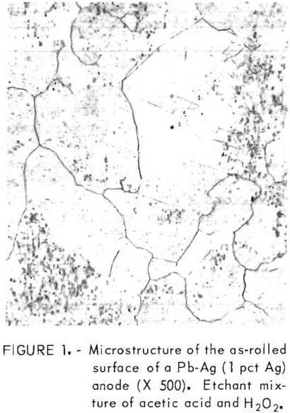 thicknesses to 0.08 cm, and cut T-shaped to slightly greater than the size of the cathode but with a 0.6- by 7.6-cm bus bar on top. The anodes were inserted into the slot in the Plexiglas top and, the arms of the “T” were bent in opposite directions to hold the anode in place. A banana plug was attached to one arm of the “T” for the electrical connection, and the brass end of the plug was wrapped in Teflon tape, again, to eliminate a source of solution contamination.
A specimen of the Pb-Ag (1 pct Ag) alloy employed as the anode in the polarization measurements was cut, mounted, polished, and etched; photomicrographs of a typical structure were obtained (fig. 1).
Titanium anodes used as the substrate for plating PbO2 were made from pure titanium sheet as described and depicted in RI 8111.
A diffractometer with copper K-alpha radiation, 0.1-mm slit, nickel filter, and a counting rate of 4×10 4 imp/min were used to determine the phases present on the anode after electrolysis. A variable aperture was used to adjust peak height.
An oscilloscope and a waveform generator were used for superimposing alternating current on direct current.
Operation of the Electrolytic Cell
At the beginning of electrolysis, the electrolyte was mixed from reagent grade chemicals, poured into the clean, dry cell, and brought to the desired operating temperature. Composition of the electrolyte for the polarization studies ranged from 1N to 4N H2SO4 and NaF-H2SO4. The concentration of all the KF solutions was 40 gpl F, and sulfuric acid was added as necessary to adjust the solution to pH 5. Deposits were made at 30° and 60° C for 12 hr at 1, 5, 10, and 20 A/dm². Composition of the electrolyte for plating PbO2 was 200 gpl Pb, 100 gpl HNO3, 0.1 gpl Cu, and 1 to 10 gpl glass beads (minus 325 mesh). The glass beads were added to the electrolyte to aid in gas bubble removal from the anode surface to avoid pitting of the PbO3 deposit. Preparation of the electrolyte and operation of the electrolytic cell for PbO3 plating is more fully described in a Bureau publication.
Anodes were carefully weighed and inserted into the slot in the Plexiglas top and slid into the center to position them in the cell. The cathodes were then placed through the slots on both sides of the anode, and the whole assembly was flushed with distilled H2O and blotted dry. Leads from the power supply were attached, the electrodes were placed in the cell, and the power supply was immediately turned to the desired current setting.
At the completion of electrolysis, the cell was disassembled as rapidly as possible, and the anodes were flushed with large amounts of distilled water and blotted dry with paper wipes. Accurate weights were again obtained to check on the efficiency of the deposition process. Selected deposits were examined on the scanning electron microscope (SEM), and photographs were taken of typical structures.
The relative hardness of PbO2 deposits was determined by using a Bierbaum microcharacter in conjunction with a metallurgical microscope and measuring the width of a scratch produced by a ground diamond point mechanically drawn across the surface.
Measuring Potentials
The electrometer was warmed up for several hours and set to a predetermined value of range and polarity.
The potential of the Hg-Hg SO4 (1N H2SO4) reference electrode was measured against a saturated calomel electrode (0.242 v) before and after each experiment. The equilibrium value recorded for the reference electrode was 0.671 v ±1 mv.
The salt bridge was filled with 1N H2SO4, then placed in the cell through the opening in the Plexiglas top and clamped in place with the Luggin tip in contact with the anode surface. The electrical connections were made, and the power supply and the electrometer were turned on simultaneously. At the completion of polarization, the power supply was turned off, the leads were disconnected from the cathodes and the anode, and the decay potential was recorded.
Values were extracted from the chart at the end of the measurements. Polarization and decay potentials versus time curves were plotted. Potential values were calculated using the equation
![]()
Results and Discussion
Polarization Behavior of Pb-Ag Anodes
H2SO4 Solutions
X-ray diffraction data for Pb-Ag (1 pct Ag) anodes polarized for 12 hr in 1N and 4N H2SO4 solutions at 30° and 60° C with a current density of 1, 10, and 20 A/dm² are presented in table 1. The diffraction peak of maximum intensity (I) was used as an indication of the amount of each phase present on the anode. The general trend for all deposits was as temperature, acid concentration, and current density increased, the Pb-Ag matrix lines decreased from very strong to zero and at the same time, α-PbO2 lines increased from very weak to very strong. Almost every pattern that had α-PbO2 lines also had a very weak indication of the highest intensity β-PbO2 peak at 3.5 A.
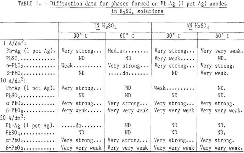
Note.—Very strong = 80-100 pct I; strong = 60-80 pct I; medium = 40-60 pct I; weak = 20-40 pct I; very weak = 5-20 pct I; very very weak = 0-5 pct I.
Due to the large number of X-ray patterns to be identified in this work, it was difficult to accurately index each pattern because of fluctuations in the alinement of the diffractometer. Instead, standard X-ray patterns were prepared, for each compound of interest, using reagent-grade materials, and the experimental patterns were identified by comparing them with these standards.
Structures, as revealed by the SEM, for each of the phases (PbSO4, α- and β-PbO2) identified above are included in figure 2. The structure of the β-PbO2 deposit appears to consist of crystals of PbSO4. Actually, these are
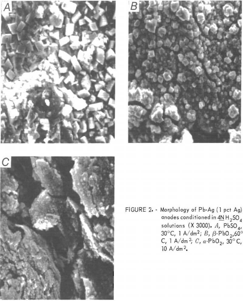
hollow shells of PbSO4 crystals, inside of which β-PbO2 has nucleated and grown until the predominant X-ray pattern is that of β-PbO2. The structure of α-PbO2 is more fine grained and laminar than the PbSO4 deposit, and is very similar to the β-PbO2 structure without the sulfate crystals.
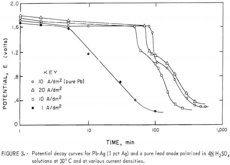
Selected 12-hr deposits produced at various current densities were allowed to remain in the cell after electrolysis on open circuit. Decay potentials were recorded in 4N H2SO4 at 30° and 60° C. A typical set of decay curves is included in figure 3. In general, three distinct voltage plateaus of -0.3 (not shown), 0.2 to 0.4, and 1.6 to 1.7 v and an indication of a fourth at 1.0 to 1.2 v were exhibited in the open-circuit potential decay curves for the Pb Ag anodes. One set of curves sufficed for both temperatures investigated since only variations in the plateau length and insignificant changes in potential resulted from variations in electrolyte temperature. Consequently, only the open-circuit decay curves obtained at 30° C are included in this work (fig. 3). A decay curve for a pure lead anode is included for comparison.
The following equilibrium reactions were suggested by the potential arrests listed above (see appendix).
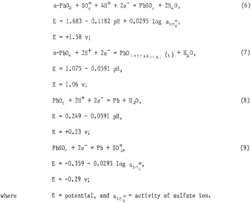
The presence of the phases indicated by reactions 6, 8, and 9 were verified by X-ray diffraction, and reaction 7 is suggested by the potential decay data, but not directly confirmed by X-ray analysis. However, the existence of α-PbO2 and PbOt, which are normally only stable in alkaline solutions, is consistent with the observations of previous researchers and is added evidence that a pH gradient exists in the anodic layer. The presence of lead and its simultaneous oxidation as the other half-cell reaction may cause mixed potentials, resulting in some deviation between calculated and observed potential values.
As in another investigation the PbO-Pb couple was the most prominent and was maintained for several hours before dropping off to the sulfate potential at -0.29 v.
To check further on the reaction taking place at the PbO2-PbSO4 plateau, a Pb-Ag anode was polarized for 12 hr at 10 A/dm², allowed to decay for 10 min, then X-rayed and photographed on the SEM. A part of this anode was then decayed for an additional 10 min and the remainder was repolarized for 30 min at 10 A/dm².
X-ray diffraction revealed the presence of PbSO4 after a 10-min decay, and an additional 10-min decay resulted in a substantial increase in the amount of the orthorhombic PbSO4 crystals (fig. 4). The structure seen on the SEM after repolarization appeared to be the same as after decay, with large PbSO4 crystals in a α-PbO2 matrix. However, X-ray diffraction indicated
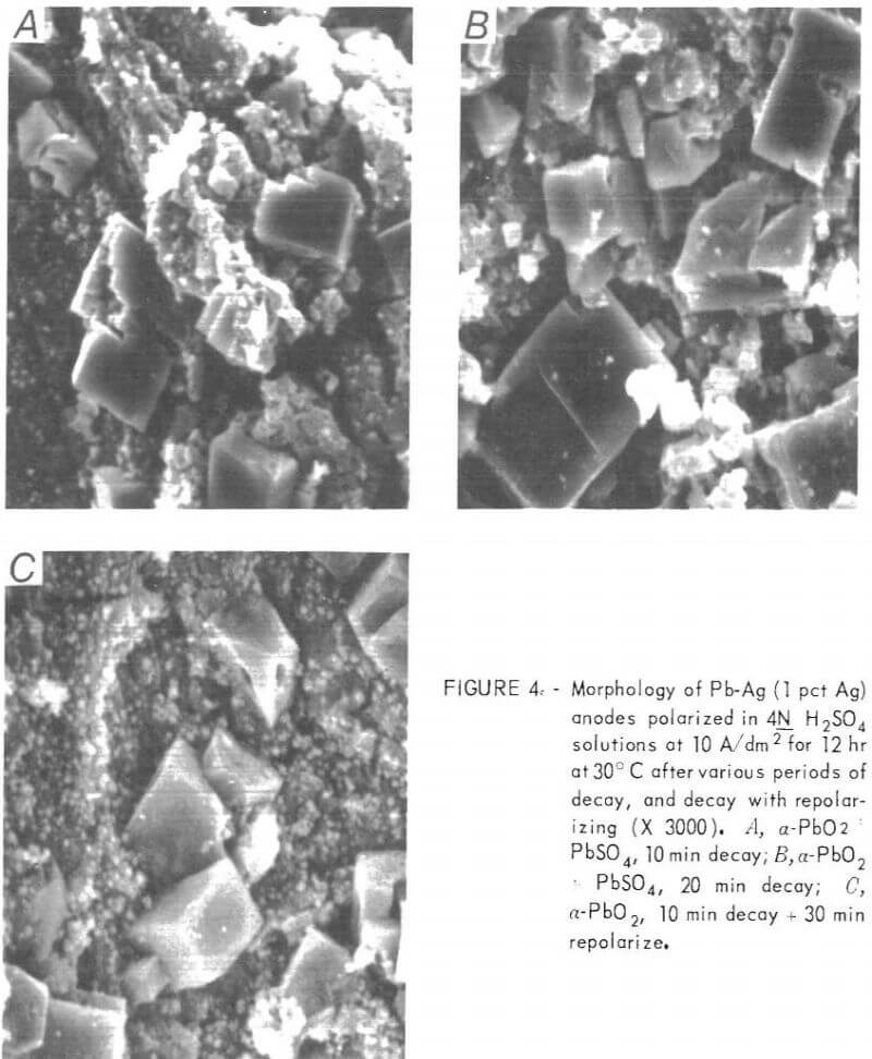
α-PbO2 was the predominant phase present, which, as was mentioned previously, is in keeping with the results of Simon, who found that PbO2 nucleates and grows inside the PbSO4 crystals, while the outer morphology remains the same.
The hardness of the anodized coatings was difficult to assess since the surface layer, even at high current densities, was relatively thin, and any values obtained were probably more an indication of the hardness of the Pb-Ag matrix than of the surface deposit.
NaF and KF Solutions
Diffraction data for the Pb-Ag (1 pct Ag) anodes polarized for 12 hr at 30° and 45° C in various strength NaF-H2SO4 and KF-H2SO4 solutions at current densities of 1, 5, 10, and 20 A/dm² between two cathodes of like material are given in table 2.
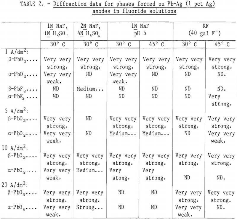
Note.—Very very strong = 90-100 pct I; very strong = 80-90 pct I; strong = 60-80 pct I; medium = 40-60 pct I; weak = 20-40 pct I; very weak = 5-20 pct I; very very weak = 0-5 pct I.
The predominant phase present on the outer surface of the anode, regardless of current density, temperature, or solution composition was β-PbO2. The anodes conditioned in NaF-1N H2SO4 and KF-H2SO4 solutions also had weak α-PbO2 lines at each current density investigated. Electrodes treated in the rest of the NaF solutions exhibited, along with strong β-PbO2 indications, increasing amounts of α-PbO2 with increases in current density. One of the deposits made at 1 A/dm² in KF solution was very spotty, leaving the anode bare in some places. It gave a strong α-PbF2 pattern where the Pb-Ag matrix was exposed. Similarly, a deposit made in an NaF solution at 1 A/dm² gave strong lines of β-PbF2 (table 2). The X-ray pattern of a Pb-Ag anode left soaking in an NaF solution (pH = 5) for 40 hr consisted of α-PbF2.
The relative hardness of the anode surface, after conditioning, was determined with a Bierbaum microcharacter. An average of five independent measurements on each surface, identified after the various conditioning processes, along with the relative hardness of the Pb-Ag matrix are listed below.

The values obtained can only be interpreted in a very general way. Due to the powdery nature of the anode surface, it was extremely difficult to get consistent and reliable results. For example, it was impossible to ascertain the effects of temperature, current density, or even solution composition in producing a reliable anode coating merely by comparing hardness values. However, in a relative sense, the Pb-Ag anodes conditioned in fluoride solutions are approximately three times harder than the same anodes conditioned in H2SO4. The anodes conditioned in H2SO4 showed hardness values very similar to those obtained for the Pb-Ag (1 pct Ag) matrix.
As mentioned above, the deposits were harder after conditioning and appeared to be very adherent until an attempt was made to clip off a piece for X-ray analysts. The deposits made at 1 and 5 A/dm² flaked off during cutting and revealed a light gray intermediate layer, which was identified by X-ray diffraction as β-PbF2.
The anodes conditioned in N NaF (pH =5) solutions had, in addition to PbF next to the electrode surface, a much harder outer layer of PbO2, The anodes conditioned in the rest of the solutions appeared to consist of three layers: a PbF2 inner layer, PbO2 outer layer, and a dark purple middle layer that appeared to be either α-PbO2 or PbOt.
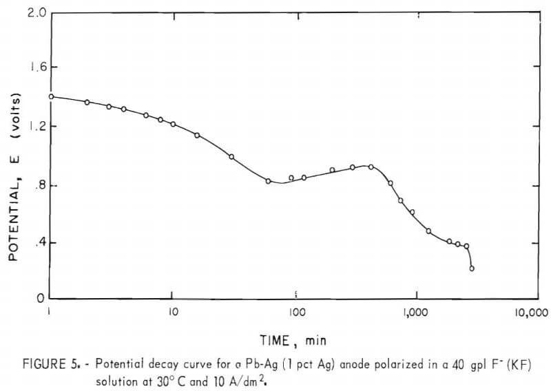
Three distinct arrests at ~1.3, 0.9, and 0.4 v, respectively, are exhibited in the potential decay curves for Pb-Ag anodes that were polarized for 12 hr in 40 gpl F-(KF) solutions at 10 A/dm² and allowed to decay on open circuit (fig. 5). The potentials of the voltage plateaus observed in figure 5 correspond to the following equilibrium reactions in the KF solutions at a pH of approximately 5:

All of the various phases identified by the potential arrests were also confirmed by X-ray diffraction before and during anodic decay. The dark purple, underlying layer tentatively identified by X-ray analysis as PbOt or α-Pb02 appeared to be mainly α-PbO2 since the arrest for PbOt-Pb was not observed.
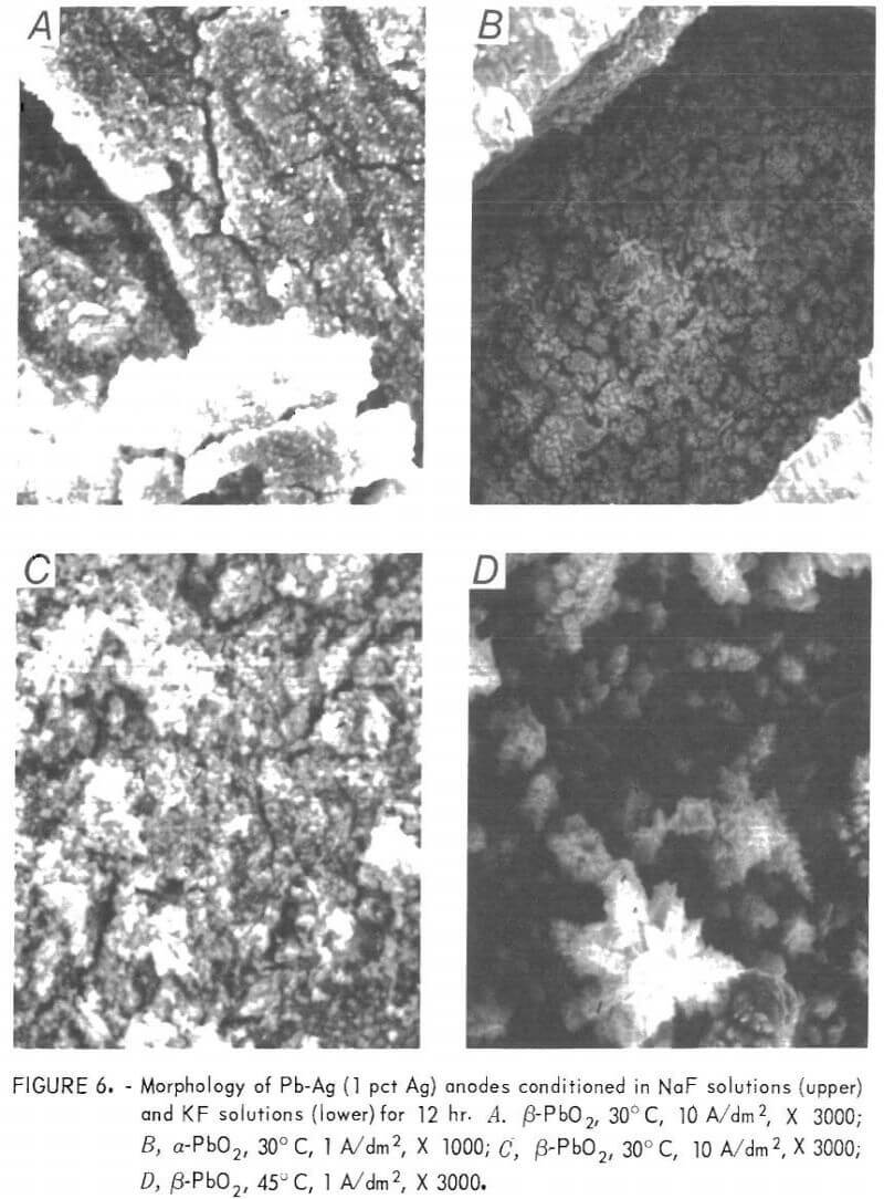
Pictures taken on the SEM are included in figure 6 for anodes conditioned in both KF and NaF solutions. The surface of the anodes conditioned at 10 A/dm² in both solutions is quite similar and consists of numerous cracks with a dense, uniform layer of small PbO2 particles between the cracks. A photograph taken inside one of the cracks shows the dark-colored second layer described above. The anode conditioned in KF solution at 1 A/dm² is unique in that the surface is primarily covered with a layer of dendritic β-PbO2 crystals.
Lead-silver anodes polarized in 4N H2 SO4 solutions for 12 hr reached a maximum potential of slightly greater than 2.0 v in the first few seconds after the current was turned on, then the potential stabilized at 2.0 v. Lead-silver anodes polarized under similar conditions (10 A/dm² -12 hr) in 40 gpl F-(KF) solution attained a maximum of 4.4 v in 60 sec, then leveled off at 1.7 v.
The formation of a dielectric layer of PbF2 next to the electrode surface of the anodes conditioned in the KF solution is responsible for the high initial surge in the potential and is analogous to the formation of PbSO4 in H2SO4 solutions.
The contribution of the fluoride ion in producing the substantial anodic layer is still not clear. Fluoride ions appear to accelerate or catalyze the reaction at the anode surface in such a way as to produce a large increase in the amount of PbO2 formed over the amount resulting from polarization in sulfuric acid solutions.
Preliminary experiments with preconditioned anodes, under actual conditions of zinc electrolysis, indicated that anodes conditioned in NaF solutions at 8 to 10 A/dm² were superior to anodes conditioned in KF solutions. Electrodes treated in NaF solutions produced a good, crystalline zinc deposit in 65 gpl Zn++, 200 gpl H2SO4 solutions for the first 4 to 6 hr (depending on current density) of electrolysis. The multiple phases on the anode surface began to separate and pull away with time due to stresses set up between the layers because of differences in lattice structure. Simultaneously with the breakup of the anode surface, the amount of lead in the zinc deposit increased. Also, it became increasingly more difficult to strip the deposit because of increasing amounts of fluoride ion in the solution from decomposition of PbF2 from the anode.
It was obvious at this point that an extensive research effort would be necessary to develop a stable PbO2 electrode for zinc electrowinning. The results of this effort, which ultimately culminated in the development of the PbO2-Ti anode, are reported in a previous Bureau publication. Additional work involving the PbO2-Ti anodes is reported in the following sections.
Overvoltage Measurements
Anodes were supplied for testing to Noranda Research Center in Canada at their request. Polarization measurements made by Noranda in a 200-gpl H2SO4 solution at 25° C on Bureau of Mines anodes and on one of Noranda’s Pb-Ag anodes, which was preconditioned by “typical plant practice” to give a PbO2 surface, indicated that the Bureau anodes had a much higher oxygen overvoltage (0.2 to 0.4 v). An increase in oxygen 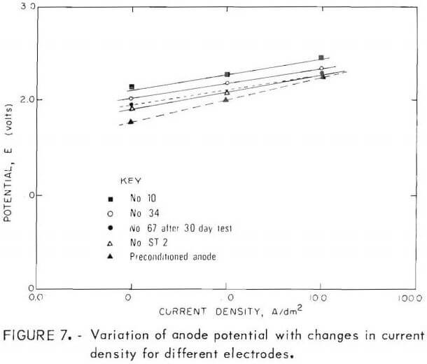 overvoltage of 0.2 to 0.4 v over that of anodes currently being used for commercial electrowinning would result in a significant increase in power cost. Noranda also reported that PbO2-Ti anodes that had been prepared by an undisclosed company process also had high oxygen overvoltages.
The results of Noranda’s polarization measurements and some of the Bureau’s more significant tests are plotted in figure 1. The Bureau anodes had potential measurements significantly higher than Noranda’s preconditioned plant anode at the lower current densities. In general, the anodes with lowest overpotential had the thickest coatings. Anodes No. 10, 34, and 67 had 0.02-, 0.05-, and 0.07-cm-thick coatings on each side, respectively. The reason for the lower overpotentials obtained on the thicker deposits is probably due to the increased surface area developed with the longer deposition times. Anode No. 67 was also subjected to a longtime test in a 200-gpl H2SO4 solution for 30 days at 6.5 A/dm² prior to the overpotential measurements. As can be seen in figure 7, anode ST-2, which will be described subsequently, and anode No. 67 have potential values approaching those of the Noranda anode at the higher current densities.
In anticipation of the necessity of stripping PbO2 deposits from the titanium substrate after a period of use in a commercial cell, attempts were made to cathodically strip the PbO2 deposit. Conditions were identical to those used for making the PbO2 anodes except two PbO2-Ti electrodes were substituted for the titanium cathodes. The PbO2 deposit was stripped with little difficulty and an unexpected bonus resulted. As the PbO2 deposit was stripped off of the cathode, it redeposited on the titanium anode as a firm, adherent coating that appeared to be superior to the original coating. The anode designated ST-2 in figure 7 is one of these anodes.
Testing
Several PbO2-Ti anodes were sent to the Salt Lake City Research Center for evaluation as anodes for producing cathode copper with a low lead content from a copper leaching-solvent extraction-electrowinning system. The research center reported that in prior tests using conventional Pb-Sb anodes, cobalt dosing of the electrolyte and the use of a char filter to remove entrained organic material were required to produce cathodes with a lead content of about 1 ppm. Copper cathodes averaging 0.7 ppm Pb were obtained by using the PbO2-Ti anodes without either cobalt addition or char filter. Comparable tests with conventional Pb-Sb anodes resulted in copper cathodes having an average lead content of 75 ppm. Thus, the research center reported that the PbO2-Ti anodes would appear to allow much more flexibility in operating conditions during copper electrowinning.
Electrodes were sent to AMJ Chemical Co. in New York at their request. The PbO2-Ti anodes were used to reoxidize chromic acid solutions such as chromic acetic, chromic phosphoric, and chromic sulfuric. AMJ reported that the reoxidation was accomplished without the corrosive attack normally encountered when using either Nalco metal or Pacific Engineering’s PbO2 on titanium anodes. According to AMJ, the company will continue to explore new uses for the anode and initiate design changes in their chrome reoxidatlon system to allow the use of the PbO2-Ti anodes.
E. I. duPont de Nemours and Co. also tested an anode in a proprietary chrome-plating solution containing fluorides. The anode was used for 8 hr per day for 1 month. During the period of plating, 5 amp was passed through the tank at 4 v. At the end of each 8-hr period, the anode was left in solution with the current off for 16 hr. The anode appeared to remain stable throughout the period and did not become passive or increase in resistance. DuPont’s results also indicate that the PbO2-Ti anodes are capable of reoxidizing trivalent chromium solutions.
Four PbO2-Ti anodes were prepared and shipped to Cominco Ltd. in Canada for evaluation as electrodes for zinc electrowinning. The anodes were tested using zinc plant electrolyte and operating parameters. A Cominco Pb-Ag (0.75 pct Ag) preconditioned anode was also tested at the same time for comparison. The performance of all PbO2-Ti anodes were adjudged by Cominco to be unsatisfactory. The four anodes failed over a period of 1 to 7 weeks of continuous operation in the cell. All of the anodes developed cracks in the PbO2 coating, which subsequently spalled off the titanium substrate. It appeared that the problem was one of poor bonding between the PbO2 coating and the titanium.
The working voltages of the test cells containing the PbO2-Ti anodes were from 100 to 300 mv higher than the test cell with the Pb-Ag (0.75 pct Ag) cast test anodes. Also, the current efficiencies for zinc deposition in the test cells containing the PbO2-Ti anodes were less than (at times as much as 10 pct less) for deposition in the test cell containing the Pb-Ag anodes under comparable conditions.
It was obvious that more work would be necessary to increase the in-cell life of the PbO2-Ti anodes if they were to be suitable for zinc electrowinning. Perhaps of more importance, the high electrical resistivity of titanium as compared to lead (-40 µohm-cm compared with 20 µohm-cm) makes it generally unsuitable as a substrate material for anodes to be used for zinc electrolysis. Unlike copper electrowinning, zinc electrowinning must be conducted at relatively low electrolyte temperatures; therefore, anodes that add significant heat to the system are unacceptable.
Superimposed Alternating Current on Direct Current
One of the methods investigated as a possible means of increasing the in-cell life of the PbO2-Ti anodes was to superimpose alternating current on direct current (s-ac/dc) during deposition of PbO2. Variables investigated included wave form (sawtooth, square, and sine wave), cycles per second (30 and 60 Hz), peak-to-peak ac voltage (2.4 to 7.2 v), and temperature (50° to 80° C). The best anode, as judged by lack of pitting, microstructure, and other factors, was produced using a 60-Hz sine wave with 4.8 peak-to-peak ac voltage superimposed on dc voltage at 85° C and 10 A/dm² with all other conditions the same as used previously.
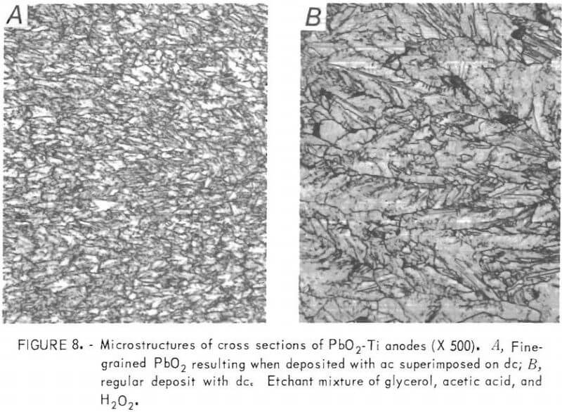
Photomicrographs indicate that the principal difference in PbO2 deposits made with s-ac/dc and the regular dc anodes is one of grain size. The s-ac/dc anodes exhibit a fine, uniform grain size throughout the PbO2 coating, whereas the structure of the PbO2 coating on the regular dc anodes is much coarser and nonuniform. (Fig. 8.)
A PbO2-Ti anode made by using s-ac/dc current held up well under longtime test in a 200-gpl H2SO4 solution at 50° C and 6.5 A/dm². Previously, anodes subjected to longtime test showed a gradual increase in anode voltage throughout the test period. However, the s-ac/dc anodes exhibited a constant voltage for the duration of the test except for a small decrease in voltage at the start. The anode failed after 12 weeks of continuous testing due to cracking and subsequent exfoliation of the PbO2 coating. Although this anode lasted
almost twice as long (12 weeks versus 7 weeks) as any of the regular PbO2 anodes tested previously, the in-cell life is still relatively short.
The results (not plotted) of the measurement of anode potential versus current density for the s-ac/dc PbO2-Ti anodes were similar to the results obtained with regular anodes ST-2 and No. 67, approaching the values obtained on the Noranda preconditioned anode at the higher current densities.
MnO2-Coated Anodes
In order to circumvent all possibility of lead getting into cathode deposits, attempts were made to deposit a stable coating of MnO2 on both titanium and lead substrates. The MnO2 was deposited from an MnSO2-H2SO4 bath using titanium cathodes at 85° C with a current density of 2 A/dm². It was soon apparent that the MnO2-coated lead anodes were far superior to the MnO2 coated titanium anodes. The coatings on the titanium anodes appeared to be brittle with a tendency to develop fine cracks. The MnO2-Ti anodes also appeared to be poor conductors.
Some MnO2 coated lead anodes were used to win copper by a typical commercial process, and copper deposits with excellent morphologies were obtained at nearly 100-pct current efficiency. Lead in the copper cathodes was almost undetectable; for example, <0.1 ppm. Unfortunately, the in-cell life of these anodes was less than 1 week.
Recent information indicates that the conductive manganese deposits formed on lead anodes during commercial zinc electrolysis are not MnO2 but are in fact cryptomelane (KMn8O16). Cryptomelane may also incorporate elements other than potassium into its structure; for example, Pb, NH4, Cu, Ni, or Fe. Manganese deposits made in the absence of K, Pb, NH4 etc., are relatively nonconducting, which is probably why deposits of manganese dioxide on titanium and lead are nonconducting and conducting, respectively. The presence of lead from the lead anode may result in the formation of cryptomelane,
PbO2-Coated Lead Anodes
An attempt was made to deposit PbO2 on lead anodes using the same conditions employed for making the PbO2-Ti anodes. The results were unsuccessful but spectacular. The cell filled up with bright yellow crystals of PbO almost immediately after the start of electrolysis and the test was discontinued.
Conclusions and Recommendations
Lead and lead-alloy anodes build up a stable coating of PbO2 over a period of time under oxidizing conditions in an electrolytic cell. The presence of fluoride ion in the electrolyte greatly accelerates the formation of PbO2, and the hardness of the coating is also increased. Since the reaction PbSO4 + 2H2O ↔ PbO2 + SO4= + 4H+ + 2e- is reversible, PbO2 anodes should never be left on open circuit because PbO2 will rapidly decay to PbSO4. Upon reoxidation, exfoliation of the loosely adherent film of PbSO4 and its subsequent entrapment in the growing cathode deposit will result in contamination of the cathode product; for example, lead in cathode copper and zinc.
The PbO2-Ti anodes developed by the Bureau of Mines are a potential solution to the problem of lead contamination of cathode deposits. Lead levels of less than 1 ppm have been obtained for copper cathodes when using the Bureau’s PbO2-Ti anodes for copper electrowinning. Unfortunately, the in-cell life of the anodes tested to date has been less than desired, particularly when the anodes were used for zinc electrowinning. Anodes tested by Cominco in Canada have only lasted 7 weeks when tested continuously in zinc plant electrolyte. The use of s-ac/dc current for making the PbO2-Ti anodes resulted in a doubling of the in-cell life, but a much greater improvement is necessary. The life of commercial anodes ranges from several months up to 2 years.
Although the experimental PbO2-Ti anodes did not fulfill all expectations, they are definitely a step in the right direction. These anodes have found commercial acceptance for use in oxidizing waste chromic acid solutions and are superior to anything tested to date for this purpose. The need for a stable inert anode is still of critical importance; and, if the in-cell life of the PbO2-Ti anodes could be improved, they would fill a definite need in the industry.
It is recommended that future work be directed toward development of anodes exhibiting improved conductivity and lower oxygen overvoltages, so as to lower the overall energy requirements for electrowinning and electrolytic operations; for example, an anode consisting of an aluminum substrate coated with PbO2.
