Table of Contents
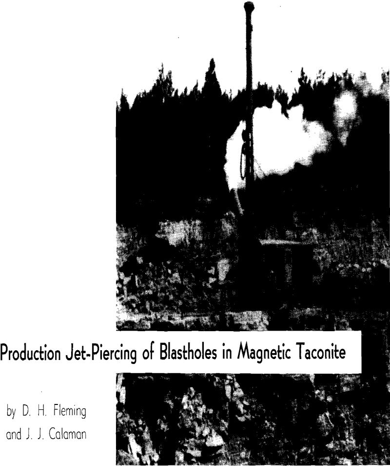
During 1950 the jet-piercing process was used commercially in the piercing of primary blast-holes in magnetic taconite at the preliminary taconite plant of the Erie Mining Co., Aurora, Minn.
To produce the blasthole, jet-piercing utilizes thermal energy, as contrasted with the application of mechanical energy in churn drills and jackhammers. The heart of the process may be termed a tailored flame produced by a rocket-type burner, thermodynamically similar in every respect to that of the giant rockets being developed for military purposes. The heat release in the combustion chamber of the burner is about 50×10 6 Btu per cu ft per hr as compared with 5×10 4 for most modern steam generators. Combustion of liquid petroleum fuels (kerosene, diesel oil, or No. 2 fuel oil) with gaseous oxygen in the burner chamber at pressures of 100 to 200 psi results in temperatures of about 4300 °F.
Piercing Technique
The burner is mounted on the lower end of a blowpipe, the length of which is slightly greater than the maximum depth of hole to be pierced. As it is advanced into the hole the blowpipe is rotated to expose uniformly the rock in its path to the action of the flames. The rotation also helps to maintain a straight hole. If ore or rock to be pierced were uniform in composition and solid in formation, the blowpipe advance could be synchronized directly with the spallability of the rock for a given burner. If such were the case, constant high piercing rates would be obtained. For example, when solid sections of taconite are encountered, the piercing rate has been increased to as high as 60 ft per hr. However, this ideal condition is never obtained in normal pit conditions for three reasons: 1—The ore is not uniform in character, since there are alternate bands rich in silica or in iron; 2—There are holes, natural cracks, and cleavage planes; 3—Blasting will produce backbreak that must be passed through. The rock structure discontinuities lower the piercing rate and require; control mechanisms to indicate their presence and special operating techniques to pierce them.
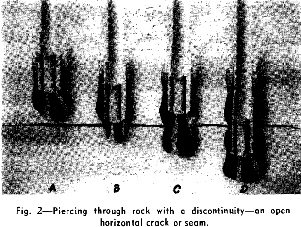
In solid rock, A, the bottom of the hole directly under the flames generally assumes a hemispherical shape when using the conventional-type burner, which has one flame parallel with the blowpipe axis and one or more flames at an angle with the axis. The advancing hole, B, breaks into the crack with a small hole. The axial flame will jump the gap and start working on the adjacent rock face, the angle flames will continue to spall the triangular wedge of rock but at a reduced rate. Spalling does not readily take place on sharp corners or acute angular areas; in fact, in some instances, melting will occur. The blowpipe will advance until the end of the hole sizer starts to ride on the restriction, or collar, as it is commonly called. This causes part of the blowpipe weight to be transmitted to the collar; tension in the blowpipe suspension cable is reduced correspondingly over normal cable tension when the blowpipe is hanging free.
An ammeter in the rotary drive motor circuit also keeps the operator informed of developments in the hole. Nominal increases in rotary drive torque occur when a collar is encountered. Sometimes rubble will cave in on the blowpipe, causing sharp increases in rotary drive torque, although there will be no decrease in cable tension. Under this circumstance, the operator will switch from low, 15 rpm, to high, 45
rpm, to grind up the rubble. These two instruments enable the operator to judge at all times what is occurring in the hole and control the blowpipe advance accordingly.
Jet-Piercing Blowpipe
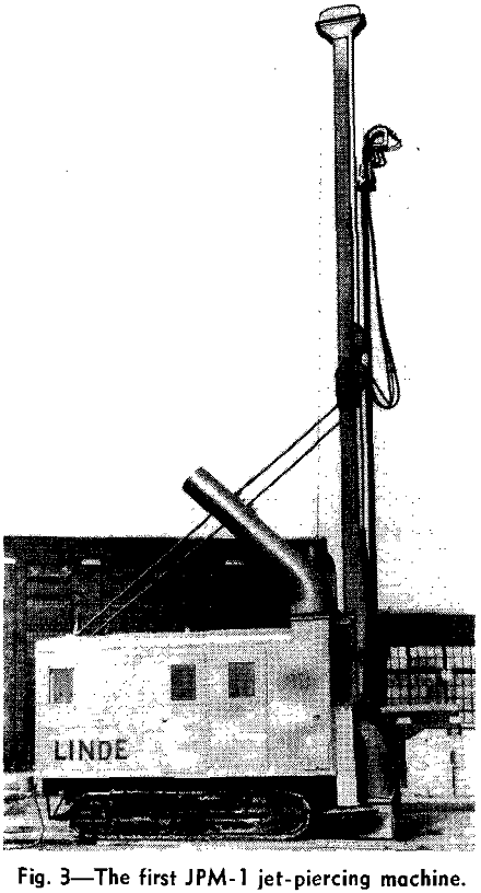
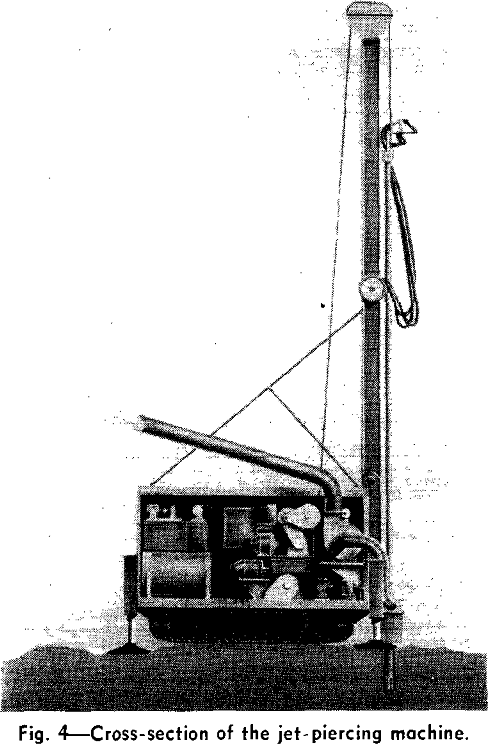
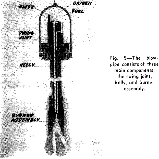
The blowpipe consists of three main components: the swing joint, kelly, and burner assembly. Oxygen, water, and fuel are introduced into the rotating blowpipe through the swing joint. This vital part of the assembly is precision-machined of selected grades of stainless steel to give adequate corrosion resistance and minimum wear. The suspending bail is attached to the main thrust-bearing housing, which is located immediately below the swing joint. The blowpipe guide blocks, which ride in the mast track, are attached to the thrust-bearing housing. The round, triple-fluted kelly is standard oil-well drilling equipment.
Oxygen and fuel are carried through separate tubes on the inside bore of the kelly to the burner assembly. Water is brought to the burner in the remaining space inside the kelly. The burner assembly consists of four main parts: the header, fuel injector, burner, and hole sizer. The header is a permanent part bolted to the bottom of the kelly onto which the fuel injector and burner are screwed. The liquid hydrocarbon fuel is atomized by kinetic impact of the gaseous oxygen as it enters the rear end of the pear-shaped combustion chamber. The burned gases are exhausted through divergent nozzles to produce the piercing jets. Oxygen and fuel flows are 10,000 cu ft per hr and 40 gal per hr, respectively.
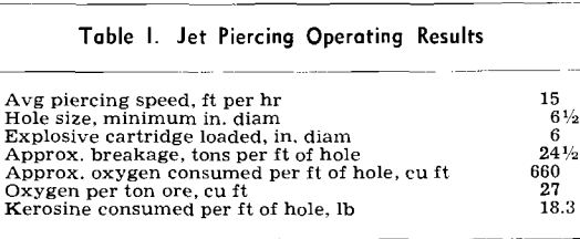
These flows have been fixed as the optimum for piercing the 6½-in. minimum diam holes now being made. If the flows are dropped substantially below this figure, the piercing rate is decreased to the point where labor and equipment costs are too large in the overall cost picture. Above these flows, commensurate increases in piercing speed have not been obtained.
Piercing Results
Current mining operation is on a 25-ft bench with blastholes being drilled 5 ft below grade. The JPM-1 machine has a capacity for drilling holes of 31-ft maximum depth. In large-scale taconite operations, a higher bench is envisioned, probably around 35 to 45 ft; consequently, future piercing machines will require a higher mast and a longer blowpipe to accommodate this increased height of bench.
Preliminary tests also have been made with promising results on 7½-in. holes for 7-in. explosives. The 7½-in. hole was not used as a regular production item in 1950; however, it will probably be in much greater use during 1951.
Piercing represented by these results was done by regular mine labor, some of whom had been experienced in churn drilling. The technique of jet-piercing was learned easily by these men.
Visual sighting indicates that rather than being smooth, the hole is corrugated. It was desirable to determine the extent of these corrugations and their effect on overall hole volume in order that the possibility of effectively utilizing this extra hole volume might be studied fully.
