Table of Contents
We been performing research on soft soldering with the objective of improving the strength of solder joints at elevated temperatures and pressures. Surface or interfacial phenomena and the factors affecting these phenomena are of major importance in soldering and brazing. A knowledge of the surface tension of the molten materials involved, such as the filler metal (solder) and fluxes, is important to predict wetting and spreading properties that are required for soldering. To obtain values for the surface tension of various metals and alloys related to soldering, a maximum-bubble-pressure system having several unique features was developed in the Bureau laboratories.
Many methods have been used for measuring surface tension (Adam, Adamson, and White) but for work with liquid metals at elevated temperatures only two warrant serious consideration. These are the drop shape, or sessile-drop method, and the maximum-bubble-pressure (MBP) method.
The MBP method has several features that make it attractive for measuring surface tension of liquid metals and alloys over a wide temperature range. The sessile-drop method becomes superior only at the solidification temperature of the material being tested.
The principle of the MBP method is that the maximum gas pressure, P, required to liberate a bubble from the end of an immersed capillary tube is a function of the depth, h, to which the tube is immersed; the radius of the bubble r; the density of the liquid, p; and the surface, tension of the liquid, γ:
P = ghp + 2γr-¹.
This assumes that the bubble is spherical. The pressure head of the liquid, however, distorts the bubble, and corrections must be made in r. A method for making this correction was developed by Sugden, who applied the data of Bashforth and Adams for liquid drops to the case for a bubble in a liquid. Details of this procedure are also described by Bircumshaw.
Advantages of the MBP method are that (1) theoretically, it is accurate to a few tenths of a percent, (2) it does not depend on the contact angle with a substrate, (3) it requires only a close approximation of the density of the liquid metal, and (4) because it is quasi-dynamic in operation, a freshly formed surface is involved for each measurement. This last advantage reduces the influence of surface contaminating agents. In actual practice the theoretical accuracy of the method has not been realized. For example, data in the literature for mercury show limits of scatter of ±3 percent or more.
Preliminary experiments to measure surface tension were performed with a system that used two capillaries with flat tips and a water manometer to measure bubble pressures. All precautions mentioned by White were observed. In testing the system with mercury as a standard, several problems arose involving the consistency or reproducibility of the data. The problems were (1) “tip effects” that produced erratic bubble detachment; (2) the need to monitor bubble action, set bubble rates, and prevent or detect multiple bubble formation; and (3) difficulties with the water manometer such as poor dynamic response, meniscus corrections, parallax, cleaning, and operator errors.
Although silica capillaries were used in the molten metal, a nonwetting system, wide variations in bubble pressures (very poor reproducibility) were traced to erratic bubble detachment. Formation and detachment of the bubbles could not be seen in the metal. The system was temporarily set up using TFE plastic tubes in water and several other transparent liquids. This temporary combination was also a nonwetting system, but it was observed that the bubbles did not form and detach consistently from the outside edge of the capillary tip as described in the literature. Capillaries with ground tips, as suggested by Kingery, where the outside of the tip is ground to form a sharp edge at the inside diameter of the tip, were also tried without success. This report describes in detail our solutions to these problems.
Description of System
The MBP system described here uses the well-known Sugden twin-tube method. This method eliminates the experimental problem of determining the exact depth of capillary immersion. In addition, this system has several features that give distinct advantages over MBP systems described by many others. These improvements are as follows;
- Internally ground silica capillaries to eliminate “tip effects” for the nonwetting liquid metal. This is probably the most important in terms of reproducibility of the data.
- An electronic differential pressure transducer having a rapid response to replace the usual water or mercury manometer that is unable to follow the rapid pressure changes involved. This represents not only an increase in accuracy under dynamic pressure conditions, but also makes operation much easier.
- A micrometer to adjust the immersion depth of the capillaries for density measurements on the molten charge. Although not absolutely necessary, this is a simple way to obtain higher accuracy than required for the density measurements.
- Valving arrangements to allow operation at elevated pressures.
- A temperature range from room temperature to 1,100° C.
- Recorder readout of the maximum pressure attained for each bubble. This produces an immediate and permanent record of the operation, and also divorces the operator’s opinion from the data.
Capillary Preparation
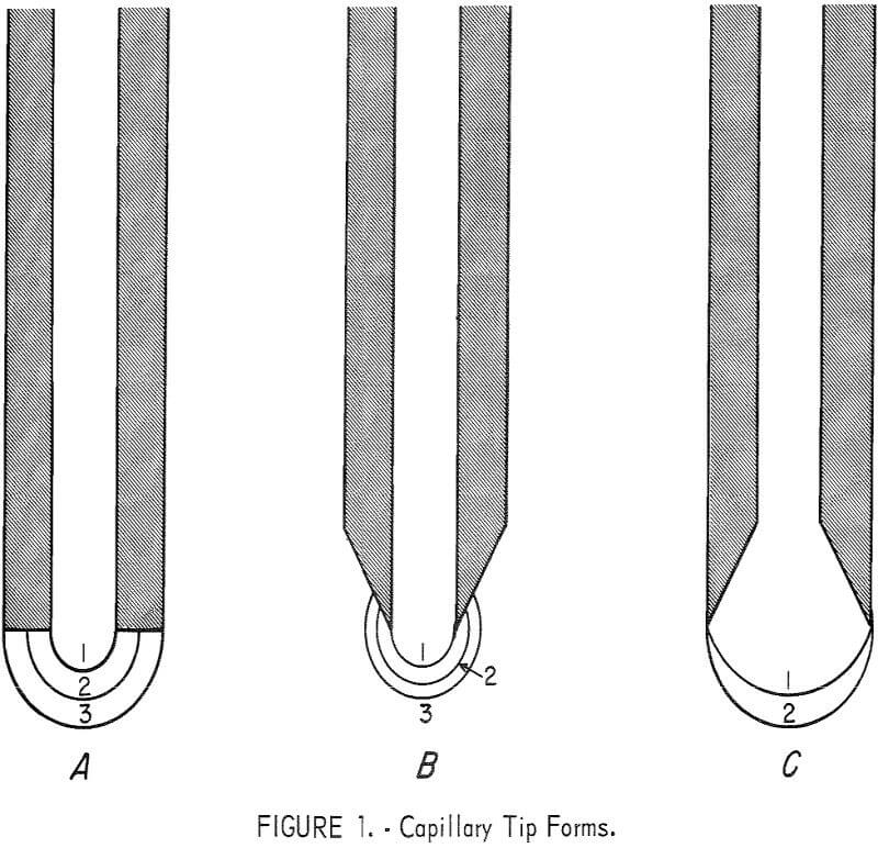
When the MBP method is used for measuring surface tensions of liquid metals which do not wet silica capillaries, the bubbles normally should detach from the outer edge of the capillary tip. The radii of the bubbles at maximum pressure are therefore considered to be one-half the outside diameter of the capillary tip. When a capillary having a tip with a finite-wall thickness is used, (fig. 1A), premature detachment of the bubble (position 1 or 2) will often occur resulting in erratic readings. With a capillary having a knife edge of the type shown in figure 1B, consistent results are still almost impossible to attain. Experiments showed that the bubble being formed had a tendency to “ride up” the tapered wall of the tip (positions 2 and 3) before detaching, and the bubble radius at maximum pressure was not equal to one-half the outside diameter of the capillary tip. To eliminate the variations in bubble pressure, we developed a capillary with an internally ground tip similar to the one shown in figure 1C. A capillary tip of this type insures that the bubble detachment occurs on the outside edge, and the radius of the bubble at maximum pressure is indeed equal to one-half the outside diameter. Data obtained from capillaries of this type were consistent and reproducible.

The preparation of these capillaries is a very important part of the procedure in measuring surface tension. The capillaries are drawn out from silica tubing on a glass blower’s lathe, and snapped off to a convenient length. These capillaries are annealed in a tube furnace between 910° and 930° C for about 20 minutes and cooled slowly in the furnace. The end of each capillary is first sanded flat on 3/0 and 4/0 emery paper. Then the capillary tip is ground internally on a slowly rotating 60° brass cone coated with a slurry of 600-grit alumina powder. The end is ground until the lip is approximately 0.03 mm thick. Experiments showed that this is about as thin as the edge can be ground without chipping. The tips are checked frequently with a microscope during the grinding process. Any “out-of-round” oval or chipped tubes are discarded.
The larger capillaries we use range from 0.11 to 0.14 cm outside diameter, and the smaller ones from 0.055 to 0.070 cm. Finished capillaries for use in the apparatus are paired to have diameter ratios between 2 and 1.5. We use a metallograph with a filar micrometer eyepiece to measure capillary diameters. Accurate measurement of the capillary radii (diameters) is extremely important. An error of 1 percent in the radius measurement of either capillary will result in a possible error of 3 to 4 percent in the surface tension.

Bubble Chamber
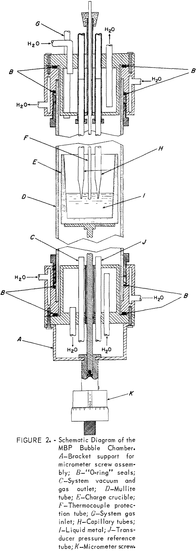
The bubble chamber (fig. 2) is constructed from a 2-foot-long 2¼-inch inside diameter, mullite tube equipped with water-cooled brass caps, and mounted vertically in a B tube furnace. Four tubes pass through the top brass cap: one for the system gas inlet, one for a silica thermocouple protection tube, and two for the capillaries. The thermocouple protection tube is positioned so that the thermocouple junction is between, and at the same level as, the capillary tips. The capillary feed-through tubes are equipped with two O-ring seals so that the capillaries can be moved up or down to position their tips at the same level. A cathetometer and a holding fixture for the cap are used to set the ends of the capillaries at the correct level.
The bottom cap has three tubes. One leads to a mechanical vacuum pump, one leads to the reference side of the differential pressure transducer, and a center one is for the stainless steel rod which supports the crucible containing the metal charge. An O-ring seal is used around the stainless support rod to allow for axial movement. The lower end of the sup-port rod fits into a brass cylinder and rests on a micrometer screw attached to the cylinder. The upper end of the brass cylinder is machined as a toggle that fits through and locks with a half turn to a strap bracket on the lower cap (part A, fig. 2).
During the initial pumping and purging of the bubble chamber, the lower end of the micrometer screw-brass cylinder assembly rests on a laboratory jack. This way, the crucible with its metal charge is located in the lower end of the chamber. Later, the jack is raised to move the crucible into the heated center of the chamber to melt the charge. Further purging is performed as the metal charge melts; that is, if the vapor pressure of the metal is low enough. When the charge is liquid, the micrometer screw-brass cylinder assembly is raised and locked into position with the toggle. This immerses the capillaries about 1 cm into the melt. Changes in the depth of immersion are then made with the micrometer screw. The least count of the micrometer screw is 0.0001 inch.
The bubble pressures are registered by a transistorized, 0 to ±2.5 psi, differential pressure transducer that produces about 2.5 volts dc maximum. One side of the transducer responds to the pressure in the capillary tube, the reference side is open to the bubble chamber pressure. This allows the bubble chamber to be operated at pressures other than room pressure. Most of the transducer output voltage is suppressed with a precision step potentiometer and a reference voltage supply. The resultant differential voltage is read on a 5-inch-scale strip chart recorder having a 100-mv full-scale range. The suppression voltage is varied so that the point at which the bubble detaches corresponds to 60- to 90-percent full scale on the recorder. Any strip chart recorder with a full-scale response of about 1 second or less is suitable.
A feature was added to this MBP apparatus that has proved to be very useful for the operator while he is adjusting the bubbling rate. A small, inexpensive guitar contact-microphone is strapped to each capillary gas supply tube just outside the upper cap. The microphones are connected through an audio amplifier to a speaker so that the operator can hear each bubble as it detaches from the capillary below. This listening device easily detects multiple bubbles or erratic bubble formation.
In our work the bubbling rate is usually set at about 3 per minute. When the listening device indicates that the bubbles are singular and are detaching properly, the chart recorder is turned on and allowed to record the maximum pressures for from 6 to 20 separate bubbles. Stable operation of the system is indicated by a series of pressure peaks all having the same height on the recorder chart. We have found that impurities in the gas supply or leaks in the system will show up as a gradual decrease in peak heights as the bubbling proceeds.
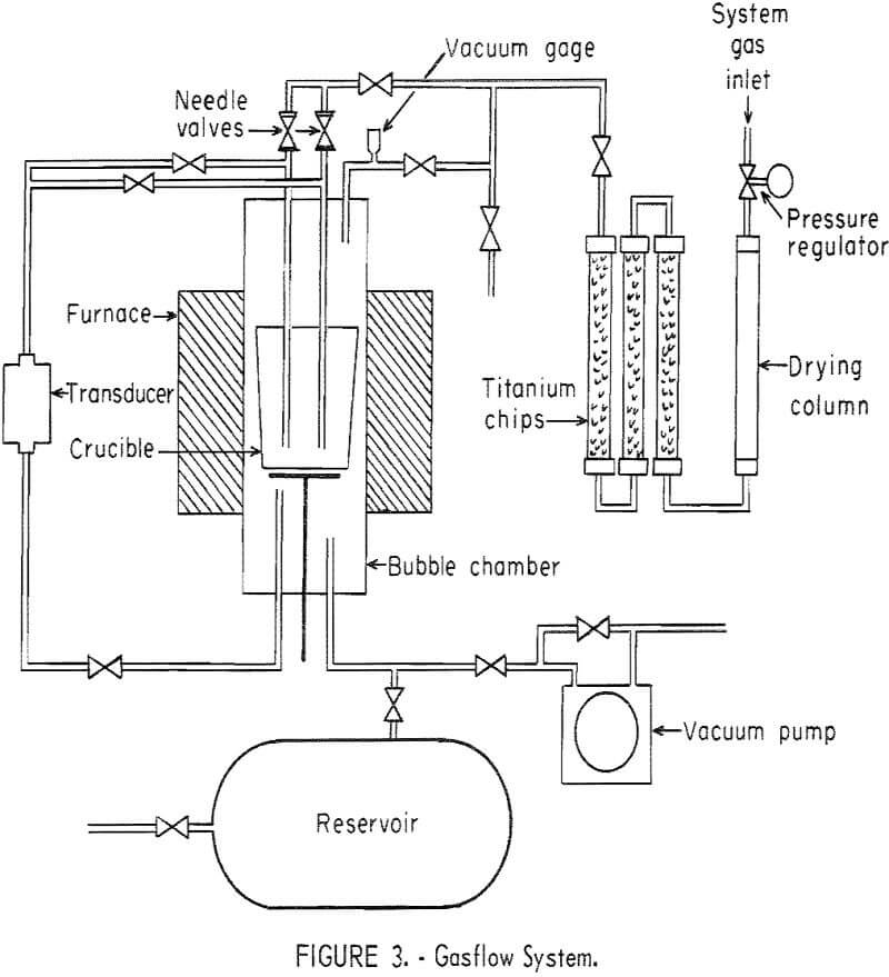
A schematic diagram of the gasflow system is shown in figure 3. Consistent operation over a wide temperature range has been obtained using

either helium or hydrogen for the system gas. Nitrogen and argon have been used for measurements on mercury at room temperature, but when the chamber is heated, convection currents in the heavier gases result in erratic pressure readings. The purifier following the drying column consists of three Inconel pipes in series, each about 2 feet long, filled with titanium chips, and heated with a tube furnace to about 830° C. The needle valves in figure 3 allow fine adjustments of the bubbling rate.
During operation at each test temperature, the immersion of the capillaries is changed several times with the micrometer screw to give simultaneous pressure readings for both density and surface tension. A separate pressure reading from each capillary at each depth gives one surface tension measurement, while each change in depth gives two values for density-one from each capillary. A digital computer has been programmed to calculate the density and the surface tension using Sugden’s table (from Bashforth and Adams’ data).

Results
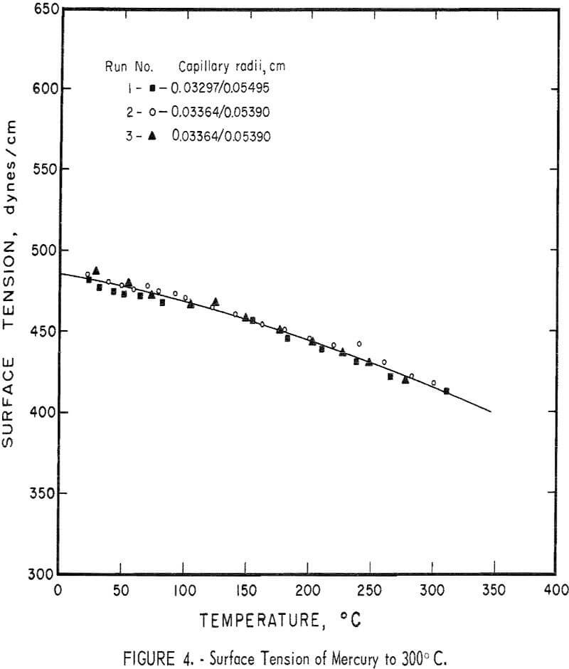
The MBP system has been tested several times using triple-distilled mercury as a standard. Each time new capillaries are installed they are checked for proper operation at room temperature with mercury. A series of three measurements of the surface tension of mercury from room temperature to about 300° C is shown in figure 4 to illustrate the reproducibility of the data with the same capillaries, and with two different capillary sets. These measurements were made at atmospheric pressure using helium. The line is a least squares fit for the combined data, and has the equation,
γ = 485.5 – 0.149T – 2.84 x 10 -4 T²,
where T is the temperature in ° C. The standard error for these data and the curve is ±3.0 dynes/cm, and the simple correlation coefficient is 0.99. The curvature, or change in slope, of the surface tension line has been noted by others and probably represents a gradual dissociation of mercury with rising temperature. Most values for the surface tension of mercury given in handbooks are too low. The data in figure 4 are very close to the more recent determinations made by others. Data in the literature for surface tension of mercury by the MBP method do not indicate whether the figures quoted are averages of several readings or not. Even so, White states that the surface tension values of mercury given by Sauerwald and Drath are the more consistent, but even here the limits of scatter are ±3 percent.” Figure 4 shows the actual data for three separate runs. The scatter is less than ±1 percent. The accuracy of all surface tension data today is still debatable. This apparatus, however, does show an increase (2 to 3 times) in precision (reproducibility) over other MBP systems that have been described. This apparatus has been in operation for some time to measure the surface tension and density of tin, lead, zinc, and various alloys of these metals.
