The Bureau of Mines recognized the need for a high-sensitivity mercury detector years ago and undertook the development of such an instrument at the Denver research facility. Although the detector has been used primarily in mining applications, the instrument could readily be adapted for use in pollution measurement.
The amplifier circuit is designed for use in analytical laboratories where low-level mercury vapor concentrations are to be measured. Owing to the high stability and very low dc drift due to temperature changes of the circuit, the amplifier can be used at field measurement sites without modification and without degradation of test results.
The first mercury vapor detector apparatus used by the Bureau of Mines was similar to that designed by the U.S. Geological Survey. Subsequently, refinements were incorporated to improve performance, the solid-state amplifier described in this report is one of the refinements.
The original Geological Survey instrument used a bridge circuit, the output of which was coupled to a vacuum-tube amplifier powered by a 300-v dc power supply. Tube circuitry of this type is generally subject to dc drift, is unstable due to powerline voltage changes and temperature changes, and in
some cases may be nonlinear in response. Because these characteristics seriously limited the accuracy of measurements made with the instrument, the circuit was redesigned with a solid-state amplifier and high-stability components. This report describes the design of the new circuitry and discusses its advantages.
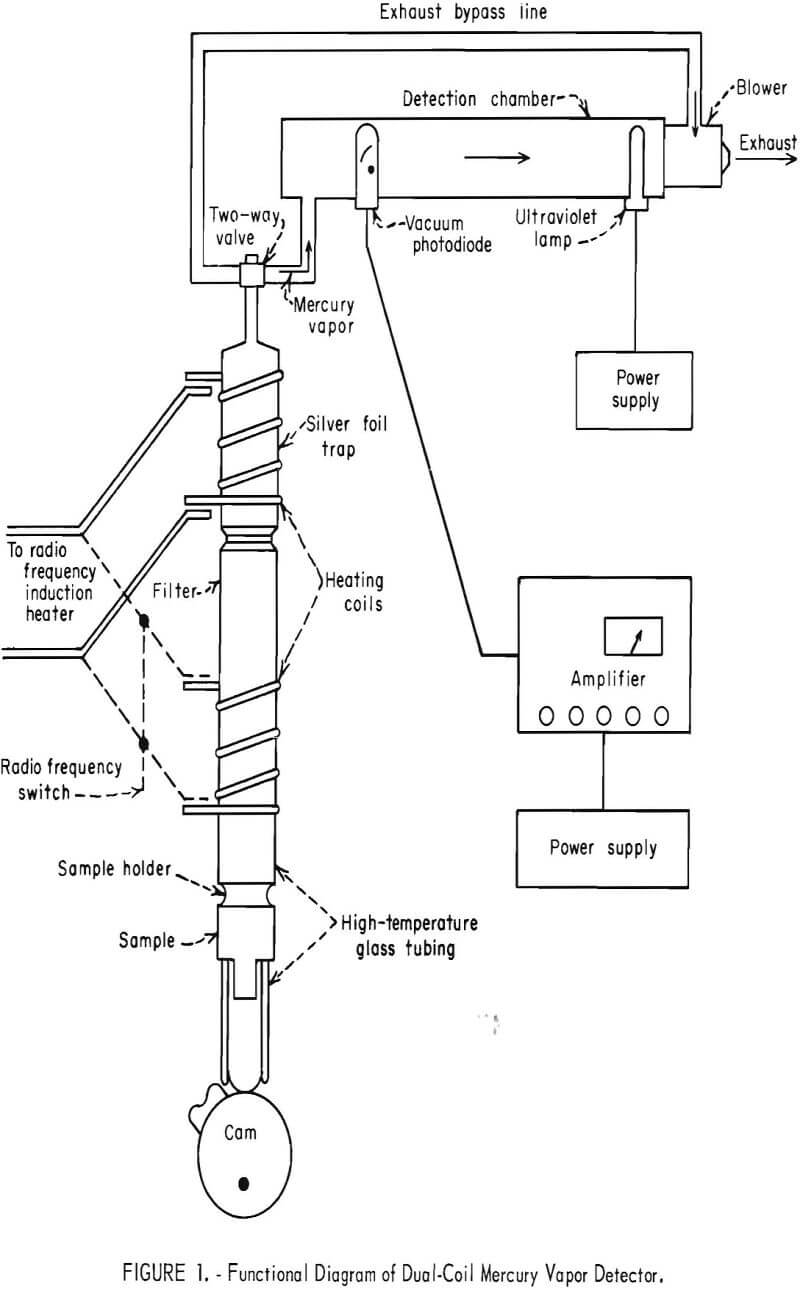
The U.S. Geological Survey instrument circuit, which was developed by Vaughn, is illustrated in figure 1. It shows the arrangement of the ultraviolet lamp and the vacuum photodiode, which are spaced approximately 15 in apart in a lightproof chamber. A port is provided near the photodiode to allow air containing mercury vapor to enter the chamber. A small, variable-speed, motor-driven blower is mounted at the end of the chamber near the ultraviolet lamp to pull the mercury-bearing air through the chamber and to exhaust it after it passes through the sensing system. Ozone produced by the ultraviolet lamp is also exhausted so that it will not interfere with the measurement.
In operation, the ultraviolet light that falls on the photodiode causes it to conduct. The photodiode is in one arm of a bridge circuit, which is balanced with pure air in the chamber prior to making mercury vapor measurements. When air that contains mercury vapor is passed through the chamber, the amount of light that falls on the photodiode is reduced by the atomic-absorption phenomenon. This causes the bridge balance to be upset, and an off-null signal is produced that is proportional to the concentration of mercury vapor in the chamber. The off-null signal is conditioned by the vacuum-tube amplifier and the range switch, and a quantitative measurement is observed on a meter on the front of the instrument.
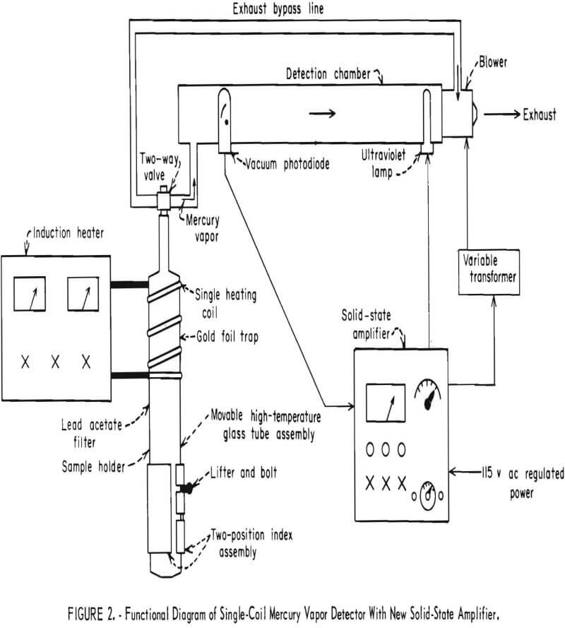
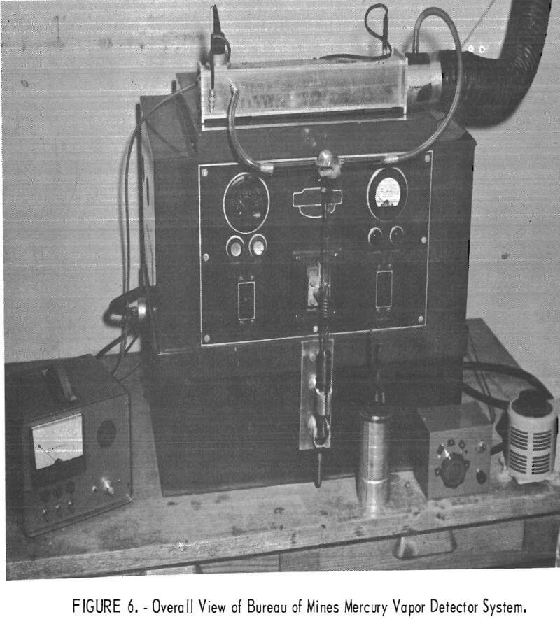
The Bureau of Mines instrument operates on the same basic principle as that of the Geological Survey instrument, but the Bureau instrument incorporates some refinements that greatly improve its performance. Figure 2 shows the general arrangement of the parts of the system. The solid-state amplifier circuit is a direct replacement for the earlier vacuum-tube amplifier circuit. Replacement cost is presently about $135 for the circuit components.
Description of New Circuit
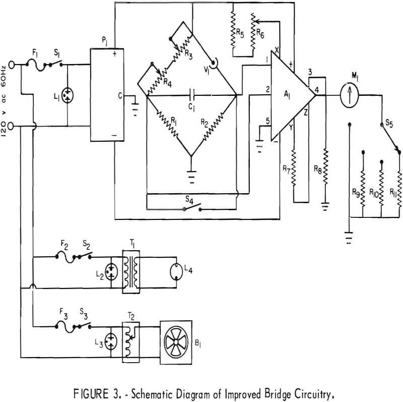
A schematic diagram of the improved circuit is shown in figure 3. The circuit makes use of a high-quality, solid-state, differential input, operational amplifier in place of the vacuum-tube amplifier of the original instrument. The important characteristics of the new detector circuitry are as follows:
- Simplified calibration and operation.
- Use of a low bridge excitation voltage.
- Improved temperature stability.
- Very low amplifier drift.
- Improved linearity on all operating ranges.
- Extended component life resulting in good, long-term stability.
- Compact, light-weight design.
- Inexpensive to build and operate.
- Operation from battery power if desired.
The heart of the circuit is the differential input, operational amplifier, and highly regulated power supply. The amplifier is operated at fixed-unity gain. Bridge excitation voltage of 15 v is supplied by the same power supply that provides voltage to the operational amplifier. High-quality components are selected for all elements in the circuit. The resulting circuitry has a dc drift of less than ±0.05 pct/° C contributed by the bridge components. The amplifier contributes far less drift, nominally ±30 x 10 -9 A/° C, which is negligible. The major instrument drift contribution is due to changes in the output level of the ultraviolet lamp. These fluctuations are normally caused by variations in the 115 v ac powerline voltage, but it was found that these fluctuations can be controlled satisfactorily by using a constant-voltage transformer to furnish power to the instrument.
Tests indicate that the instrument has a sensitivity of about 1 ppb mercury in air and that the response curve is linear over the operating range from 1 ppb to 1,000 ppm.
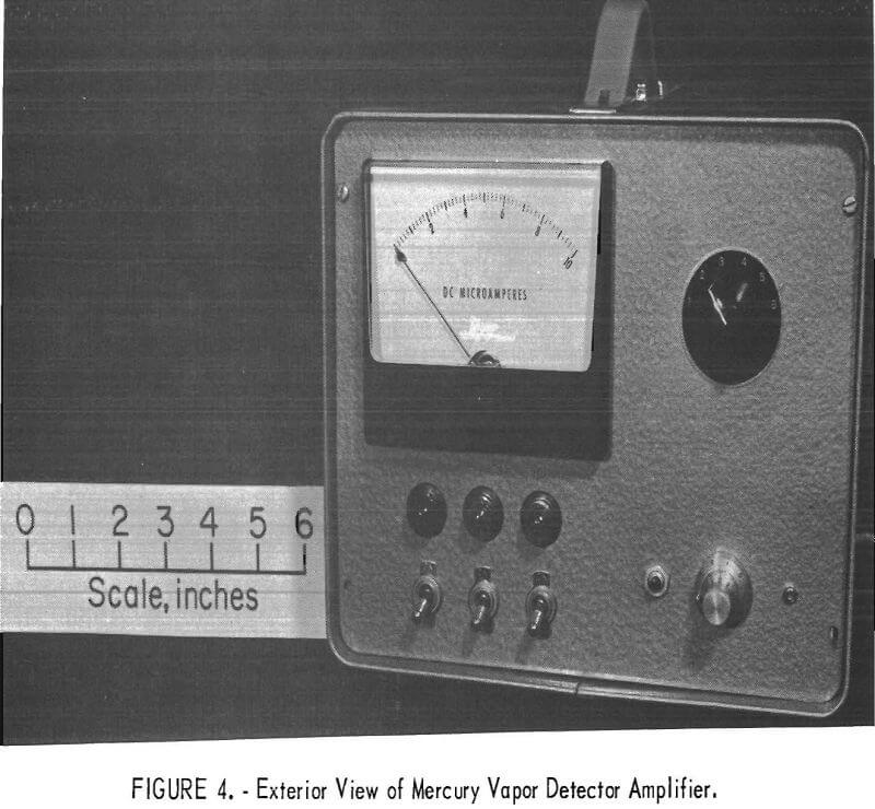
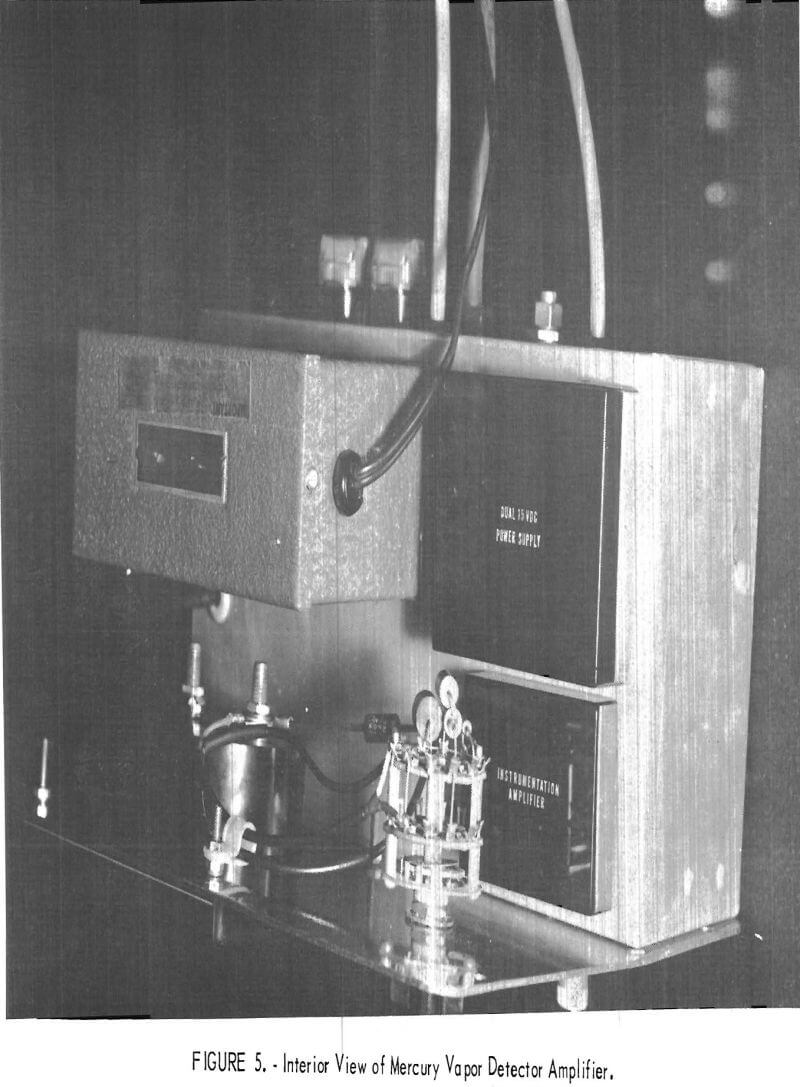
Based upon several hundred readings made in a carefully controlled test atmosphere, the instrument is capable of ±3 pct repeatability and ±5 pct absolute accuracy for periods up to 48 hr. Figures 4, 5, and 6 show various photographic views of the Bureau of Mines mercury vapor detector.
Summary
The newly designed amplifier circuit described herein replaces a vacuum-tube-type amplifier in a low-level mercury vapor detector. The new amplifier circuit exhibits the following characteristics: dc drift of only ±0.05 pct/° C overall, repeatability of ±3 pct and absolute accuracy of ±5 pct for periods up to 48 hr, and mercury detection capability of about 1 ppb with a range up to 1,000 ppm. The new amplifier is easy to construct, and the parts cost about $135. Owing to minimal power requirements for the new circuitry, the instrument may be quickly converted to battery operation for more portability.
