Table of Contents
- Apparatus Description
- Sample Collection
- Gas Extraction and Addition of Diluent Gas
- Extracted-Gas Analysis
- Calibration
- Calculations
- Discussion of Results
- Calibration Curve
- Determination of Helium-Extraction Efficiency
- Precision of Ground-Water Analysis
- Accuracy of Ground-Water Analysis
- Second Method
- Apparatus Description
- Procedures
- Calculations
- Discussion of Results
We have developed an improved method for determining dissolved helium in water in the concentration range of 4.0 x 10 -8 to 270 x 10 -8 cm³ He (STP)/cm³ H2O. The method is a modification of a previously reported method that was developed for analyzing surface and subsurface waters in geochemical survey work. Water samples are collected in 500-cm³ stainless steel cylinders, and the dissolved gases in a sample are extracted into an evacuated cylinder of equal volume. After addition of 30 psig of nitrogen containing less than 2 ppb helium to the extracted gases, the resulting mixture is analyzed for helium using a helium-tuned mass spectrometer. The helium content of the water sample is determined from an empirical calibration that is established by analyzing standard solutions of helium in water. The accuracy of the method is ±7 pct for helium-in-water concentrations above 10 x 10 -8 cm³ He (STP)/cm³ H2O.
The U.S. Bureau of Mines has published the results of reconnaissance geochemical helium² surveys that were conducted in the vicinity of the Bush Dome helium storage reservoir in the Cliffside Gasfield. The surveys revealed that some of the ground waters were anomalously “high” in dissolved helium. The anomalous helium-in-water concentrations averaged about 20 times the air-equilibrated water concentration. The Bureau is investigating the use of soil-gas and ground-water helium measurements as an additional technique for monitoring the Bush Dome reservoir. This report describes an improved mass spectrometric method that is used to determine dissolved helium in water.
Several mass spectrometric methods for the analysis of helium in natural waters are reported in the literature. Dyck, Reimer, Martin, and Butt assembled portable helium mass spectrometers for evaluating measurements of helium in natural waters as an aid in uranium reconnaissance surveying, Pogorski developed a proprietary mass spectrometer system for analyzing natural waters for helium as a technique for locating uranium and petroleum deposits. Lupton and Craig have described a mass spectrometer method used for determining helium isotopes in seawater as evidence of mantle helium injection at oceanic spreading centers and subduction zones, respectively.
The method described in this report is a modification of a previous Bureau-developed method for determining helium in water. This method is an improvement in that (1) the internal standard of pure neon is not required, (2) a semiportable, helium-tuned mass spectrometer having a precision of ± 1 ppb is utilized for the helium determinations, and (3) the analysis time per sample is reduced from 1 h to 30 min. Although the method is designed for analysis of helium-in-water concentrations over the range of 4.0 x 10 -8 to 270 x 10 -8 cm³ He (STP)/cm³ H2O, the analytical parameters can be adjusted to extend the range.
Apparatus Description
A diagram of the gas extraction apparatus, inlet system, and mass spectrometer is shown in figure 1. Cylinders N and O are standard 500-cm3 stainless steel gas-sampling cylinders with ¼-in female pipe openings. Cylinder O, the water sample container, is single-ended and fitted with ball valve 8. Cylinder N, the extracted-gas container, is double-ended and connected to cylinder O through the ball valve. A portion of the dissolved gases extracted from the water sample is admitted from cylinder N to the mass spectrometer inlet system through the moisture-removal trap M. The trap is a 15-cm by 0.5-cm-TD stainless steel tube containing approximately 2 g of anhydrous magnesium perchlorate.
The inlet system of the mass spectrometer consists of calibration standard inlet port A, sample inlet port B, stream-switching valve 1, sample valve 2, and air-switching solenoid valves 4 and 5, Valves 1 and 2 are sliding-piston, eight-port chromatograph valves with Fluorel o-ring seals.
These valves are actuated by compressed air (30 psig) supplied through valves 4 and 5.
Valve sequencing and switching are accomplished using a Hewlett-Packard model 3390A programmable reporting integrator and model 19400A event-control module. Time-programmed commands from the integrator control the switching of valves 5 and 4, thereby controlling the operation of stream-switching valve 1 and sample valve 2, respectively, The sequencing of the valves operations creates a standard-sample-standard series of analyses.
The flow of calibration standard or sample through sample valve 2 is controlled using the cylinder metering valves 6 and 7, respectively. The flow rate through the sample loop is maintained at 10 to 25 cm3/min prior to expansion of the sample into the mass spectrometer. Tests have shown that flow rates as high as 35 cm3/min and as low as 5 cm3/min have no detectable effect on the analytical precision.
The mass spectrometer is connected to the inlet system through charcoal trap E. The trap is a 0,64-cm-OD (0.10- cm-wall) by 56-cm-long stainless steel U-tube with a 0.95- cm-OD (0.10-cm-wall) by 5-cm “bulb” about 3 cm from the base. The bulb contains approximately 2 g of 40/60- mesh activated charcoal and is submerged in liquid nitrogen. At liquid nitrogen temperature, gases other than helium and neon are adsorbed by the charcoal; thus, use

the trap allows a larger volume of sample to be admitted to the mass spectrometer.
The mass spectrometer is a modified Consolidated Electrodynamics Corp, model 24-120A helium leak detector. Assembly of the mass spectrometer system and subsequent modifications made to improve its performance were described previously. The mass spectrometer was developed for trace analysis of helium in the range of 0.5 to 20,000 ppb. Performance tests have shown the precision for 10 successive analyses at the 5,000-ppb helium level to be routinely ±1 ppb. The instrument was demonstrated to be linear over the range of about 50 to 7,000 ppb helium.
Procedures
Sample Collection
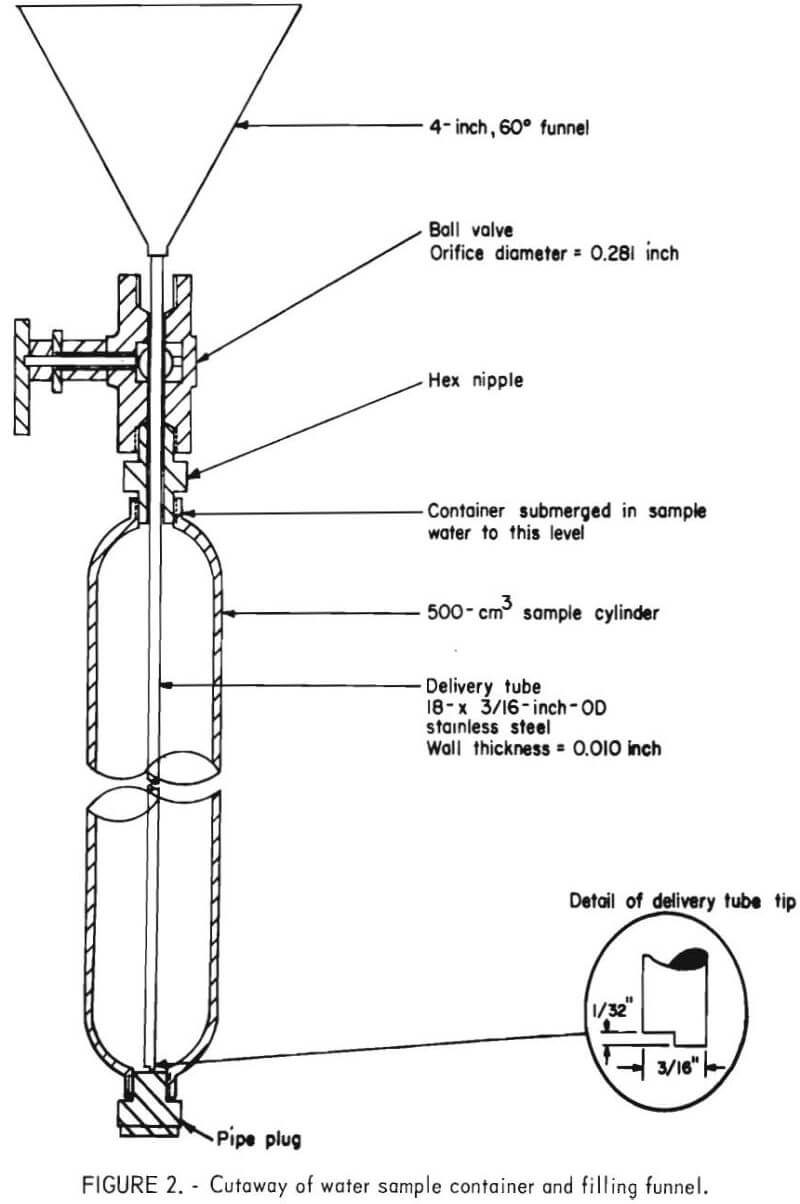
To obtain a water sample, the filling funnel is inserted into the sample container as shown in figure 2. Prior to sampling, the container is placed in a bath of the freshly collected sample water, filled to overflowing with the sample water, then allowed to stand for 5 min. This procedure rinses the interior of the container with the water to be sampled and allows the temperature of the container to approach that of the sample water. The container is then emptied, resubmerged in the water bath, and filled to over-flowing with freshly collected sample water. The sample water is poured slowly into the funnel to minimize air- water turbulence. As soon as the container overflows, the funnel is removed, and the ball valve is closed to complete the sampling procedure. The samples are stored at room temperature and analyzed within 48 h from the time of collection.

Gas Extraction and Addition of Diluent Gas
Since the solubility of gases is temperature dependent, the extraction procedure is performed at 25 ±2° C. The apparatus is prepared for the extraction procedure as follows: Sample cylinder O is connected to cylinder N as shown in figure 1. With valve 8 closed, the gas extraction apparatus is connected to a mechanical vacuum pump through valve 7, and cylinder N is evacuated to 10 torr. After N is evacuated, valve 7 is closed and the apparatus is disconnected from the vacuum pump.
To perform the extraction, valve 8 (fig. 1) is opened, and the gas extraction apparatus is inverted to allow the water sample in cylinder O to flow to cylinder N. After cylinder O is emptied, the apparatus is re-inverted, allowing the contents of cylinder N to return to cylinder O. Ten inversions are performed to achieve equilibration between the liquid and gaseous phases. After the final inversion, the apparatus is left in the vertical position for 5 min to allow residual water in cylinder N to drain into cylinder O. Valve 8 is then closed.
Nitrogen containing less than 2 ppb helium is added to the extracted gases in cylinder N to increase the total pressure to 30.0 + 0.2 psig. The diluent nitrogen is admitted to N from a high-pressure supply using a dual-stage pressure regulator equipped with a stainless steel diaphragm. The secondary of the regulator is fitted with a 0- to 30-psig gauge having a readability of 0.1 psi and an accuracy ±0.5 pct of span.
Addition of the diluent nitrogen is performed at 25 ±2° C. Since the same diluent nitrogen is added to the extracted gases of unknown samples and to the extracted gases of the calibration solutions, a correction to account for the helium present in the diluent is not required. After addition of the diluent, the resulting gas mixture in N2 is analyzed for helium as described below.
Extracted-Gas Analysis
The procedures for preparing the mass spectrometer and liquid-nitrogen-cooled charcoal trap for use were described previously. A weighed primary standard having a helium content that approximates that of the extracted gas mixture is selected as a reference gas. The determination of helium in the gas extracted from a water sample is performed as follows: The calibration standard and sample gas supply lines are connected to inlet ports A and B, respectively, as shown in figure 1. Moisture- removal trap M is inserted between the sample gas cylinder and supply line. By keying an “Ext 7” command at the integrator keyboard, valve 1 is switched to allow measurement of the reference gas flow with rotameter C. Using valve 6, the reference gas flow is set at 10 to 25 cm³/min. Using an “Ext -7” command, valve 1 is then switched to allow measurement of the sample gas flow with the rotameter. The sample gas flow is set at 10 to 25 cm³/min by adjusting valve 7.
Alternate analysis of the reference and sample gas is automated using the time-programmed sequence of valve operations shown in table 1. The time-programmed commands and their respective times of execution are entered into the integrator memory via keyboard. The integration parameters are set as shown in table 2. The integrator’s “peak-height mode” option is used so that the helium peaks are shown by height counts. The integrator’s “automate- runs” option is activated to cause the programmed sequence of valve operations to be repeated after an analysis sequence is completed. The sequence is repeated continuously until manually terminated.


Calibration
An empirical calibration for the method is established by analyzing a series of six helium-in-water standard solutions. The solutions are prepared by bubbling gaseous standards of helium in air or helium in nitrogen through distilled water at room temperature and atmospheric pressure. The helium contents (with limits of uncertainty) of the gaseous standards used to prepare the solutions are given in table 3. This range of gaseous standards was chosen to result in solutions containing from about 4.0 x 10 -8 to 270 x 10 -8 cm³ He (STP)/cm³ H2O. The apparatus and techniques used for preparing the solutions were described by Holland. A linear regression plot of the calculated helium-in-water contents of the solutions versus their corresponding “extracted-gas” helium contents establishes the calibration curve for the method.

Calculations
The helium content of the extracted gas mixture obtained from a water sample is calculated using the equation

where Hex = helium content of the extracted gas mixture, ppb,
Hes = helium content of the calibration standard, ppb,
Ds<1> = helium peak height from first analysis of the calibration standard, μV,
Ds<2> = helium peak height from second analysis of the calibration standard, μV,
and Dx = helium peak height from analysis of the gas mixture extracted from the water sample, μV.
The helium concentration in a water sample is determined using the helium content of the extracted gas (Hex) and the linear regression plot of the calibration data as given in the equation
CHe = A + B Hex……………………………………………………………(2)
where CHe = helium concentration in the unknown water sample, cm³ He (STP)/cm³ H2O,
A = zero-intercept value for linear regression plot of calibration data, cm³ He (STP)/cm³ H2O,
B = slope of linear regression plot of calibration data, cm³ He (STP)/cm³ H2O-ppb,
Hex = helium content of the extracted gas mixture obtained from the unknown water sample, ppb.
Discussion of Results
Calibration Curve
A series of six standard solutions of helium in water were prepared and used to establish the calibration curve for the method. The solutions were prepared to contain from 4.0 x 10 -8 to 273 x 10 -8 cm He (STP)/cm³ H2O with the accuracies indicated in table 4. Triplicate samples of each solution were collected, and the dissolved gases were extracted, and diluted with nitrogen to a pressure of 30 psig; then determinations of the helium contents were performed. The analyzed “extracted-gas” helium contents of the calibration solutions are also given in table 4.
A linear regression plot of the calculated helium-in- water contents versus the “extracted-gas” helium contents is shown in figure 3. The slope of the curve is 0.302 x 10 -8 cm³ He (STP)/cm³ H2O-ppb, and the zero-intercept value is 0.4 x 10 -8 cm³ He (STP)/cm³ H2O. The correlation coefficient for the curve is 0.9999. This curve (equation) was used for calculating the helium-in-water contents of ground-water samples that were subsequently analyzed in this study.
Determination of Helium-Extraction Efficiency
The extraction efficiency for removing dissolved helium from the water samples is shown in table 5. The determination was accomplished using the results obtained from analysis of the calibration solutions. The extraction efficiency was calculated using the equation

where, XEff = the extraction efficiency, pct,
CHe(g) = the analyzed helium content of the diluted extracted gases minus the helium present in the diluent nitrogen, ppb (column E, table 5),
CHe(s) = the theoretical dissolved helium content of the calibration solution, cm³ He (STP) / cm³ H2O (column A, table 5),
V(s) = the internal volume of the water-sampling container, 500 cm³,
and V(g) = the volume that 30 psig of an ideal gas in the gas-extraction container would occupy at STP, 1,520 cm³.


The values given in column A (CHe(s)) of table 5 are the theoretical concentrations of dissolved helium in the calibration solutions as shown in table 4.
Calibration of the internal volumes of the water-sampling containers and gas-extraction containers showed the volumes to vary no more than ± 1 pct from the manufacturer’s stated volume of 500 cm³. Values in column B (CHe(s) · V(s)) are the calculated volumes of helium, expressed as cm³ He at standard temperature and pressure (STP), theoretically present in 500-cm³ aliquots of each calibration solution.
The values in column C (CHe(s) · V(s)/V(g)) are the calculated theoretical concentrations of helium in the “diluted” extracted gases. The constant, V(g), is 1,520 cm³ and is the volume that 30 psig of an ideal gas in a 500-cm³ container would occupy at STP.
The experimentally determined “extracted-gas” helium contents (obtained from table 4) are given in column D. The nitrogen used in diluting the gases extracted from the calibration solution aliquots was analyzed to contain 2.0 ±0.4 ppb helium. The values in column E (CHe(g)) were determined by subtracting 2 ppb from the values in column D.
Dividing the corrected analyzed extracted-gas helium values (column E) by the calculated extracted-gas helium values (column C) results in a theoretical determination of the extraction efficiency (XEff), which is given in column F. Thus, it is concluded that within the experimental error, essentially 100 pct of the dissolved helium is removed from solution by the extraction technique used in this method.
Precision of Ground-Water Analysis
The precision of helium-in-ground-water analysis was determined by obtaining samples from four windmill-pumped water wells located in the Cliffside Gasfield. The results are given in table 6. The five samples obtained from each well were collected within a 45-min period. All samples were analyzed within 48 h of collection. The standard deviation for the average helium content of the five samples obtained from each well was within ±5 pct.

Accuracy of Ground-Water Analysis
The accuracy of the method is dependent on the precision of the method and the accuracy of the standard solutions used to establish the calibration curve. Since the standard solutions used for calibration were accurate to within ±2 pct (table 4), the uncertainty in a single determination is estimated to be within ±7 pct.
Conclusions
The procedure described in this report provides a precise and reliable method for determining dissolved helium in natural waters. The method was shown to be linear over the investigated range of 4.0 x 10 -8 to 273 x 10 -8 cm³ He (STP)/cm³ H2O. The accuracy of the method is ±7 pct for helium-in-water concentrations above 10 x 10 -8 cm³ He (STP)/cm³ H2O. Within the experimental error, essentially 100 pct of the dissolved helium is removed from the water sample by the vacuum extraction technique employed in this method.
Second Method
Apparatus Description
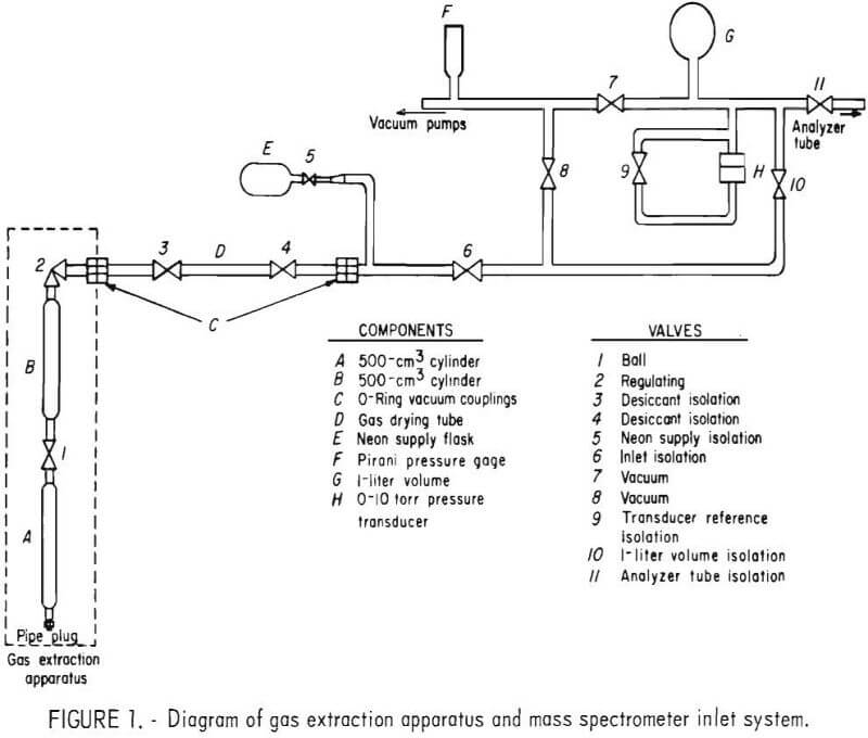
A diagram of the gas extraction apparatus and inlet system of the mass spectrometer is shown in figure 1. Cylinders A and B are standard 500-cm³ stainless steel cylinders with ¼-inch female pipe openings. Cylinder A, the water sample container, is sealed with a pipe plug at one end and fitted with ball valve 1 at the other end. Cylinder 15, the extraction container, is connected to cylinder A through ball valve 1 and fitted with valve 2 at the other end. A portion of the dissolved gases extracted from the water sample is admitted from cylinder B to the mass spectrometer inlet system through valve 2. The gas is dried by the desiccant-filled tube, D, as it enters the mass spectrometer. The 12- x ¼-inch ID tube is filled with anhydrous magnesium
perchlorate. Valves 3 and 4 are used to isolate the desiccant from the atmosphere when the tube is not in use.
To resist corrosion, all components of the gas extraction apparatus are made of either 304 or 316 stainless steel. However, since ground waters may contain significant quantities of dissolved salts and minerals, the apparatuses used for the extraction of gases from these waters are drained and rinsed with distilled water after each use.
A modified Consolidated Electrodynamics Corp. (CEC) Model 21-103C³ mass spectrometer (a single-focusing, 5-inch-radius, 180° instrument) is used to analyze the extracted gases for helium and neon-21. The original 3-liter glass expansion volume of the spectrometer was replaced with a 1-liter stainless steel volume. A 0- to 10-torr differential pressure transducer was installed in the inlet system as shown in figure 1. With the transducer, sample pressures of 1 torr can be measured with an accuracy of ±0.5 percent.
Procedures
Sample Collection
To obtain a representative sample, the sample container is partially submerged in a bath of freshly collected sample water, and the filling funnel is inserted into the container as shown in figure 2. The container is then filled to overflowing with the sample water and allowed to stand for 5 minutes. This procedure purges the interior of the container and allows the temperature of the container to approach the temperature of the sample water. The container is then emptied, resubmerged in the water bath, and filled to overflowing with freshly collected sample. The sample water is poured slowly into the funnel to minimize air-water turbulence.
The tip of the funnel delivery tube was designed to allow the container to fill in about 1 minute to minimize air-water contact and mixing. The funnel is kept full of sample water as the container is filled, which also minimizes air-water mixing.
As soon as the sample container overflows, the funnel is removed and the ball valve closed. The samples are stored at room temperature and analyzed within 48 hours of collection.
Introduction of Internal Standard and Gas Extraction
Prior to extraction of the dissolved gases from a sample, 0.25 torr of neon is introduced into cylinder B of the gas extraction apparatus. The analytical sequence used in this procedure is as follows: Cylinder B is connected to cylinder A as shown in figure 1, desiccant-filled tube D is removed, and the apparatus is connected to the mass spectrometer inlet through 0-ring vacuum couplings C. With valves 7 and 9 through 11 closed, valves 2, 6, and 8
are opened and cylinder B is evacuated using the inlet vacuum system of the mass spectrometer. The pressure in cylinder B is monitored with Pirani gage F. After the pressure in cylinder B is below 1 millitorr, valve 8 is closed, valve 10 is opened, and neon from flask E is admitted into cylinder B and the mass spectrometer inlet system by slowly opening valve 5. The neon pressure is measured using transducer H. When the pressure reaches approximately 0.25 torr, valve 5 is closed and the final pressure is measured to the nearest millitorr. The temperature at which the neon pressure measurement is made is also recorded. Valve 2 is then closed and valves 7 and 8 are opened to evacuate volume G and the mass spectrometer inlet lines. Valve 6 is then closed and the gas extraction apparatus is disconnected from the mass spectrometer.
To perform the extraction, valve 1 is opened and the apparatus is inverted to allow the water sample to flow from cylinder A to cylinder B. After cylinder A is emptied, the apparatus is reinverted, allowing the contents of cylinder B to return to cylinder A. The apparatus is inverted a total of 10 times to achieve equilibration and is then placed in a vertical position for 5 minutes to allow the residual water in cylinder B to drain into cylinder A. Valve 1 is then closed and the gaseous mixture in cylinder B is analyzed for helium and neon-21 by mass spectrometry.
Analysis of the Extracted Gas
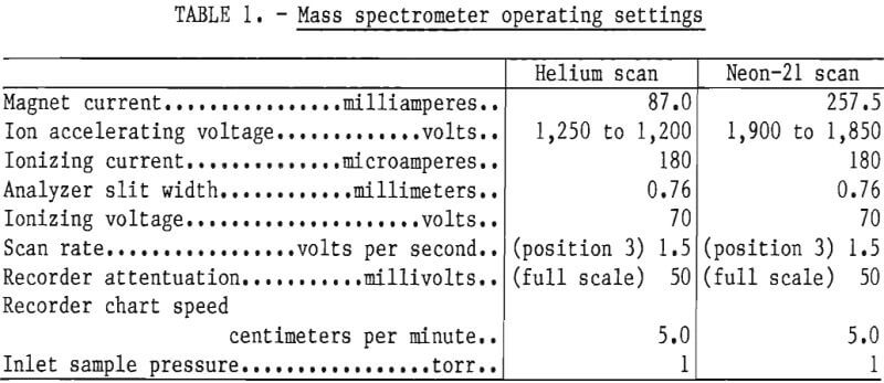
The mass spectrometer operating settings for analysis of helium and neon-21 are listed in table 1. The settings of 1-torr inlet sample pressure and 180 microamperes ionizing current were selected to provide adequate sensitivity.
Before each sample is scanned, a scan of the mass 4 and mass 21 background is made. The presence of residual n-heptane and various heavier aliphatics in the mass spectrometer produces metastable ions with a mass-charge ratio of 21.7. These ions are not resolved from neon-21 in the sample analysis. No detectable contribution to mass 21 was observed when air- equilibrated distilled water and ground water samples without the neon added were analyzed.
The background is scanned by analyzing a sample of high-purity nitrogen that contains less than the minimum detectable limits of helium and neon-21, which are 0.5 and 1 ppm (part per million), respectively. A sample inlet pressure of 1 torr is used for the scan. After the background scan is completed, the inlet system and analyzer tube of the mass spectrometer are evacuated for 10 minutes.
A gas sample from cylinder B of the extraction apparatus is admitted to the mass spectrometer as follows: The apparatus is connected as shown in figure 1. With valves 7 and 9 through 11 closed, valves 3, 4, 6 and 8 are opened to evacuate to valve 2. The pressure is monitored with Pirani gage F. When the pressure is less than 1 millitorr, valve 8 is closed, valve 10 is opened, and sample from cylinder B is admitted into volume G by slowly opening valve 2. The pressure in volume G is monitored with transducer H. After the pressure reaches 1 torr, valve 2 is closed and the sample is isolated in volume (1 by closing valve 10.
Sample is admitted to the analyzer of the mass spectrometer by opening valve 11. Scans of masses 4 and 21 are then made using the established scan rate. After the scan is completed, valve 6 is closed, valves 7 through 10 are opened, and the inlet system and analyzer tube are allowed to evacuate for 10 minutes before the next sample is admitted.
Determination of the Helium-to-Neon-21 Sensitivity Ratio
To calculate the volume of helium in the sample, the helium-to-neon-21 sensitivity ratio must be known. The helium and neon-21 sensitivities are determined by analyzing standards of helium and neon in nitrogen. The concentrations of helium and neon-21 in the standards approximate those from a typical sample extraction. The standards are analyzed using the same operating settings and scan rate as the background and sample scans.
The helium-to-neon-21 sensitivity ratio is defined in equation 1 as
SR = SHe/SNe-21………………………………………………………………..(1)
where, SR = ratio of the helium-to-neon-21 sensitivities,
SHe = sensitivity of helium, divisions per millitorr of helium,
and, SNe-21 = sensitivity of neon-21, divisions per millitorr of neon.
Calculations
Using Henry’s law, West derived the equation describing the extraction efficiency of the permanent gases from water with the described extraction apparatus. The extraction efficiency for any slightly soluble gas is calculated using equation 2.
Ex = 27300/273 + A/B (Kx T)……………………………………………….(2)
where Ex = the extraction efficiency of component x, percent,
A = volume of cylinder A of the extraction apparatus, cubic centimeters,
B = volume of cylinder B of the extraction apparatus, cubic centimeters,
Kx = Henry’s law constant for component x at the temperature of extraction, cubic centimeters at STP/per cubic centimeters of water – atmosphere,
and T = temperature of extraction, K.
The volume of helium at STP in a water sample is calculated from the mass spectral data, the extraction efficiency of helium, the efficiency of neon recovery, and other experimental parameters shown in equation 3. The efficiency of neon recovery is also based on Henry’s law and is calculated in the same manner as the extraction efficiency of helium using equation 2. It is assumed that neon-21 and neon-20 have the same solubility.

where VHe = volume of helium in the water sample, cubic centimeters of helium at STP,
SR = ratio of the helium-to-neon-21 sensitivities,
PNe = pressure of pure neon introduced into cylinder 11 of the extraction apparatus, atmosphere,
B = volume of cylinder B of the extraction apparatus, cubic centimeters,
T = temperature of the pure neon at the time of pressure measurement, K.
ENe = efficiency of neon recovery from the system, percent,
and EHe = extraction efficiency of helium from water with the extraction apparatus, percent.
The concentration of helium in the water sample is then calculated using equation 4.
CHe = VHe/A………………………………………………………………(4)
where CHe = concentration of helium in the water sample, cubic centimeters of helium at STP per cubic centimeter of water,
VHe = volume of helium in the water sample, cubic centimeters of helium at STP,
and A = volume of cylinder A of the extraction apparatus (volume of water sample), cubic centimeters.
Discussion of Results
Helium-to-Neon-21 Sensitivity Ratio Determination
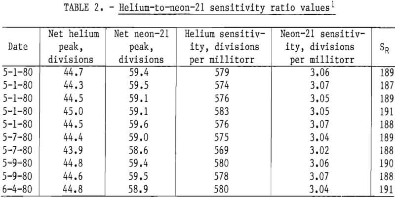
The mass spectrometric helium-to-neon-21 sensitivity ratio, SR, was determined by scanning samples of primary standards (9) containing 77.2 ±0.3 ppm helium in nitrogen and 1.936 ±0.002 percent neon (approximately 58 ppm neon-21) in nitrogen. Ten samples from each standard were scanned using sample inlet pressures of 1 torr. The results are shown in table 2. The neon-21 sensitivities are based on the neon pressures.
Equilibration Study
Equilibrium is established in the extraction apparatus by inverting the apparatus a sufficient number of times to allow the contents of the water sample container (cylinder A in fig. 1) to equilibrate with the contents of the extraction container (cylinder B). The number of inversions required to achieve equilibration was determined experimentally.
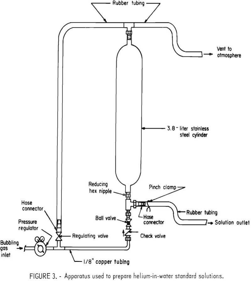
A helium-in-water standard solution was prepared by bubbling a certified standard of helium in air through distilled water using the apparatus shown in figure 3. A standard containing 110 ±1 ppm helium in air was bubbled through 3 liters of water at 400 cm³/min for 4 hours. The temperature of the water and atmospheric pressure were 25° C and 0.879 atm, respectively. Using Henry’s law, the concentration of helium in the solution was calculated to be 83.1 ± 1.7 x 10⁻⁸ cm³ He (STP)/cm³ H2O.
After bubbling was completed, the ball valve was closed, the regulating valve opened, and the solution was allowed to stand for 5 minutes. Five 500-cm³ aliquots were then obtained from the apparatus. An aliquot was first drained into a beaker, then transferred into a sample container using the techniques previously described. Each sample container was connected to an extraction cylinder and the five apparatuses were designated as L, M, N, O, and P.
After evacuation of the extraction cylinders and addition of the neon, the dissolved gases were extracted by inverting each apparatus a predetermined number of times. Apparatus L was inverted 2 times; apparatus M, 4 times; apparatus N, 6 times; apparatus O, 8 times; and apparatus P 10 times. A sample of the extracted gas from each apparatus was scanned for helium and neon-21, and the helium-in-water contents were calculated.
When an apparatus was inverted six or more times, the analyzed helium content equaled the calculated content within the experimental error as shown in table 3. Thus, it is concluded that equilibrium is established in the extraction apparatus after a minimum of six inversions.
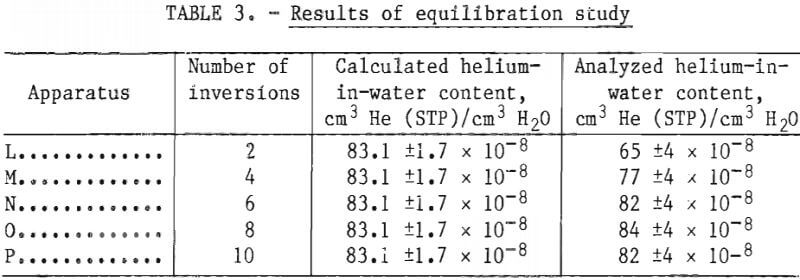
All subsequent sample extractions in this study were performed using 10 inversions. This number of inversions was found to be sufficient for samples containing from about 4 x 10⁻⁸ to 245 x 10-8 cm³ He (STP)/cm³ H2O.
Loss of Helium During Sampling
In the geochemical survey conducted at the Cliffside Field, ground water samples are collected from wells that are pumped by windmills. The water is drawn from an aquifer that ranges from about 80 to 250 feet below the surface. The ground water is in contact with the atmosphere an estimated 2 to 3 minutes before a sample is sealed in a sample container. To quantitatively estimate the amount of helium that is lost to the atmosphere during sampling, the following experiment was conducted.
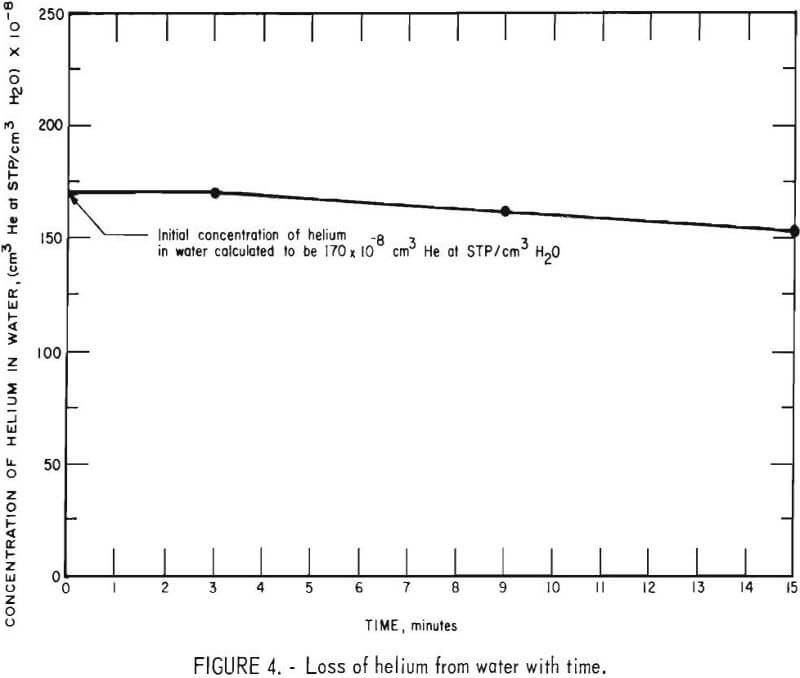
A 2-liter helium-in-water standard containing 170 ±8 x 10 -8 cm³ He (STP)/ cm³ H2O was prepared. The solution was drained from the bubbling apparatus into a 4-liter plastic bucket and samples of the solution were collected in sample containers at the end of 3, 9, and 15 minutes. The samples were extracted and analyzed on the mass spectrometer. The experimentally determined helium concentrations are plotted against the time of collection as shown in figure 4. From the curve it can be seen that no detectable loss of helium occurred during the first 3 minutes. Therefore, it is concluded that no significant loss of helium should occur during the 2- to 3-minute period that samples of ground water are exposed to the atmosphere.
Precision of Ground Water Analysis
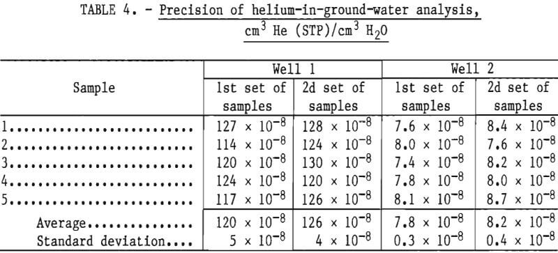
The precision of ground water analysis was checked by analyzing water samples obtained from two windmill-pumped water wells in the Cliffside Field. Two sets of five samples each were obtained from each well. Each five-sample set was collected on a different day within a 45-minute period. Each sample was analyzed within 48 hours of collection and the results are given in table 4. The precision of analysis is within ±5 percent.
Accuracy of the Analytical Method
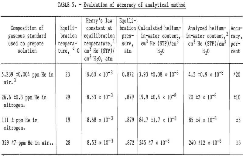
To evaluate the accuracy of the analytical method, four standard solutions containing from about 4 x 10⁻⁸ to 245 x 10-8 cm³ He (STP)/cm³ H2O were prepared and analyzed. This concentration range was selected for study because the helium-in-ground-water concentrations in the Cliffside Field were known to be in approximately the same range. Two of the solutions were prepared by bubbling certified standards of helium in nitrogen through 1-liter quantities of distilled water. A third solution was prepared by bubbling a certified standard of helium in air through 1 liter of distilled water. The standards were bubbled through the 1-liter volumes of water at 400 cm³/min for 4 hours. A fourth solution was prepared by allowing 1 liter of distilled water to equilibrate with ambient air, which contains 5.239 ±0.004 ppm helium. Henry’s law was used to calculate the concentration of helium in each solution.
A sample from each standard solution was collected and analyzed within 48 hours of collection. The composition of the gaseous standards used to prepare the solutions, the equilibrium conditions, the calculated and analyzed helium-in-water contents, and accuracy are shown in table 5. Table 5 shows that the accuracy of the analytical method is within ±10 percent for solutions containing above 20 x 10-8 cm³ He (STP)/cm³ H2O. The minimum detectable concentration of helium in water is calculated to be 2 x 10⁻⁸ cm³ He (STP)/cm³ H2O.
Conclusions
The procedure described in this report provides a precise and reliable method for determining helium in water. Analysis of prepared helium-in-water standards containing from approximately 4 x 10⁻⁸ to 245 x 10-8 cm³ He (STP)/ cm³ H2O showed the accuracy of the analytical method to be within ±10 percent for solutions containing above 20 x 10-8 cm³ He (STP)/cm3 H2O. The minimum detectable concentration is calculated to be 2 x 10⁻⁸ cm³ He (STP)/cm³ H2O.
When collecting samples of prepared solutions in the open air, there was no detectable loss of helium from solution when samples were sealed in containers within 3 minutes.
