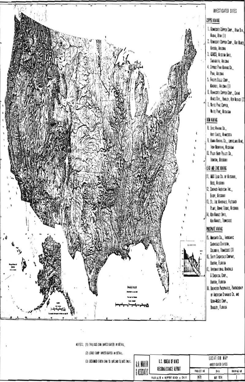
The reconnaissance-level investigations were carried out to gather supplemental data to the in-depth studies of Kennecott’ s Magna and Phelps Dodge’s Morenci tailings deposits and Kennecott’s Chino leaching dump. The data were obtained by personnel of W. A. Wahler and Associates to determine to what extent the disposal systems and techniques used at the three sites studied in depth typify those of the mining industry represented by the 15 other sites.
The various sites visited were classified according to the different systems and techniques used by the mining industry. The probable effects and relationships between site conditions and disposal methods were determined and evaluated to the extent feasible by a reconnaissance level investigation. Therefore, they are not comprehensive and the purpose was mainly to determine how these sites relate to those for which detailed investigations were accomplished, and thus define areas requiring further in-depth investigations.
Performance and Method of Investigation
The reconnaissance level Investigation consisted of a study of data available in W. A. Wahler and Associates company files, supplemented by written information received from the various selected mines, by visits to the sites, and by studying data made available to us at the Spokane, Washington, Mining Research Center of the U. S. Bureau of Mines. Our visits to the sites were made in two periods: one group of sites was visited in December 1972, and the other in February 1973.
The visits consisted of discussions with mining company representatives in order to obtain information regarding disposal plans, design considerations and historical data on dam construction, followed by inspection of the disposal structures. Aerial observation surveys were also conducted by our personnel to supplement data obtained during the ground inspection and to obtain overall views of the sites.
Personnel from W. A. Wahler and Associates who participated in these site visits were Messrs L. Alvarez, J. P. Connell, R. L. Volpe, and W. A. Wahler.
Copper Industry
- Ray Mines, Kennecott Copper Corp., Hayden, Arizona
Ivor G. Pickering, General Manager
J. T. Mortimer, Safety Director
R. Barrass, Tailings Foreman
W. J. Barkley, Concentrator Superintendent
J. Stuart Nebeker, Reduction Plant Superintendent - Mission Unit, ASARCO, Sahuarita, Arizona
Scott L. Burrill, Assistant Manager - Pima Mine, Cyprus Pima Mining Co., Tucson, Arizona
M. D. Martin, Resident Manager
J. H. Bassarear, Mill Manager - White Pine Copper Co., White Pine, Michigan
R. W. Brusenback, Plant Engineer
F. E. Girucky, Tailings Manager
Iron Industry
- Erie Mining Co., Hoyt Lakes, Minnesota
C. D. Keith, General Manager
J. B. Bowen, Supervisor of Safety
R. Hull, Superintendent Ore Dressing
R. Neubauer, Tailings Development Engineer
D. Crosswell, Chief Mining Engineer - Groveland Mine, The Hanna Mining Co., Iron Mountain, Michigan
G. Kotonias, General Superintendent
R. C. Peterson, Assistant Superintendent - Pilot Knob Pellet Company, Ironton, Missouri
R. C. Wrightman, Chief Mining Engineer
Lead and Zinc Industry
- Fletcher Plant, St. Joe Minerals Corporation, Bonne Terre, Missouri
L. W. Casteel, Division General Manager
E. J. Krokoskia, Division Superintendent
P. E. Gerdemann, Chief Geologist - Magmont Mines, Cominco America, Bixby, Missouri
F. H. Sharp, Concentrator Superintendent - AMAX Lead Company of Missouri, Boss, Missouri
M. N. Anderson, General Manager W. J. Dean, Chief Engineer - New Market Unit, New Market, Tennessee
R. G. Gordon, Operations Superintendent
J. Polhemus, Surface Superintendent
Phosphate Industry
- Noralyn Plant, International Minerals & Chemical Corp., Bartow, Florida
R. Sauerberg, Operations Manager
D. Montgomery, Head cf Geotechnical Division - Swift Chemical Company, Bartow, Florida
D. J. Raden, General Manager
F. Myers, Mine Superintendent - Brewster Phosphates, Partnership of Cyanamid Company and Kerr-McGee Corp, Bradley, Florida
R. C. Timberlak.e, Plant Manager
M. Lassiter, Operations Manager
H. W. Abercrombie, Chicora Mine Superintendent - Monsanto Company, Inorganic Chemicals Division, Columbia, Tennessee S. Webb, Central Engineering Dept., St. Louis, Missouri
In Florida, we also received the special help and cooperation of Dr. Leslie G. Bromwell, Project Director of the Florida Phosphatic Clays Research Project, a joint venture which combines the efforts of the phosphate mining industry and the U.S. Bureau of Mines in an attempt to find an economic and feasible solution to the phosphate slimes disposal problem. Dr. Bromwell arranged for, and accompanied us on, our visits to the various sites in Florida.
Site Descriptions
Copper Industry
Perhaps the largest mine; and mill refuse deposits from the mining industry are those derived from copper mines and mills. Since the copper ores being exploited today very often contain less than 1 percent copper, the recovery of the metal is a process in which most of the material treated is wasted.
Most of the copper being produced today is derived from sulfide deposits, from which the ore is concentrated for smelting. The concentration method generally used is froth flotation. The ore is ground to sand and silt sizes and concentrated and separated by differential flotation into materials with a high metal content and refuse materials. The refuse, commonly referred to as tailings, as placed in disposal areas according to different methods. The following descriptions summarize observations made at several copper tailings deposits considered representative of the mining industry throughout the conterminous United States. These observations supplement detailed investigations performed for two tailings deposits in southwestern United States: the Magna deposit of Kennecott Copper Corporation in Utah, and the Morenci deposit of Phelps Dodge Corporation in Arizona.
Most tailings deposits were not initially designed following sound engineering principles but were developed according to the best judgment of whomever was in charge—generally the mill superintendent. Several tailings dam failures have made the mining companies aware of the problems inherent in these structures and induced them to take steps toward improving disposal methods. Many of the older deposits show seepage and instability problems that are being corrected. Several newer deposits are being built following engineering designs that may prove to be appropriate to the particular site and material conditions. The inspections and reviews made during this project were intended to establish what the mining industry is doing, what methods and techniques are successful, and what problem areas exist.
Ray Mines Division, Kennecott Copper Corporation, Hayden, Arizona
The Ray Mines Division of Kennecott Copper Corporation operates an open pit mine, concentrator, smelter and sulphuric acid plant in Hayden, Arizona (Site No. 2, Drawing No. 1). Operations commenced in 1910 at a rate of about 4,000 tons of ore per day. In 1952, the rate of operation was increased to about 16,000 tons per day; in 1960 the rate was 21,000 tons per day with gradual increases since then to the present 25,000 tons per day. The principal products are copper, molybdenum, and sulphuric acid.
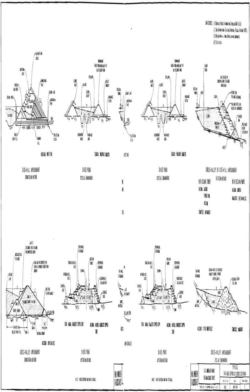
The tailings deposit is located south of town on the north bank of the Gila River, between the Southern Pacific railroad tracks and the river. It is a diked pond type of impoundment built according to the upstream method (Drawing No. 2). Details about the initial construction method were not available during our very short visit. However, we were informed that from 1910 until the 1960s tailings were discharged into the pond area from a single point near the eastern end of the deposit and the decanted water was not reclaimed but discharged directly into the Gila River. Since the early 1950s, the dam has been raised in 10-foot lifts by dozers that pushed dried-out material from the reservoir to the edge of the deposit and spread it out to form a more or less horizontal crest. In the 1960s, the reservoir surface was divided into three areas by dikes in order to start a rotation cycle; one pond being filled with tailings, while one was drying out and the other was being formed by diking.
The deposit is roughly miles long, ¾ mile wide and about 100-120 feet high, covering an area of about 830 acres. The slopes of the dam faces between berms are about 2:1 (horizontal to vertical). Tailings are piped to the pond at a rate of about 8,500 gpm of a slurry containing 35 to 40 percent solids by weight. Thus, about 5,000 gpm of the total quantity consists of water. Since 1973, the company reportedly is reclaiming about 4,000 gpm of water. Parts of the north face of the dam have been vegetated successfully to test the ability of the tailings material to sustain vegetation.
The original method of single-point discharge was changed to peripheral spigotting in the middle 1960s; however, the crest of the dam is still being raised with dozers and dragline. According to operating personnel, this method has not been satisfactory, since there have been problems of seepage at the contact between the spigotted materials and the previously deposited ones, mainly around the western half of the deposit. Apparently, the problem originates from relatively more pervious, clean sands resting on older, clayey and silty sands which act as an impervious barrier.
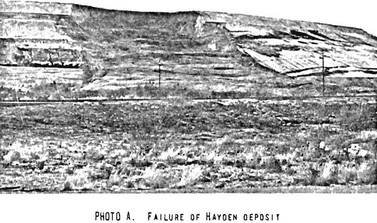
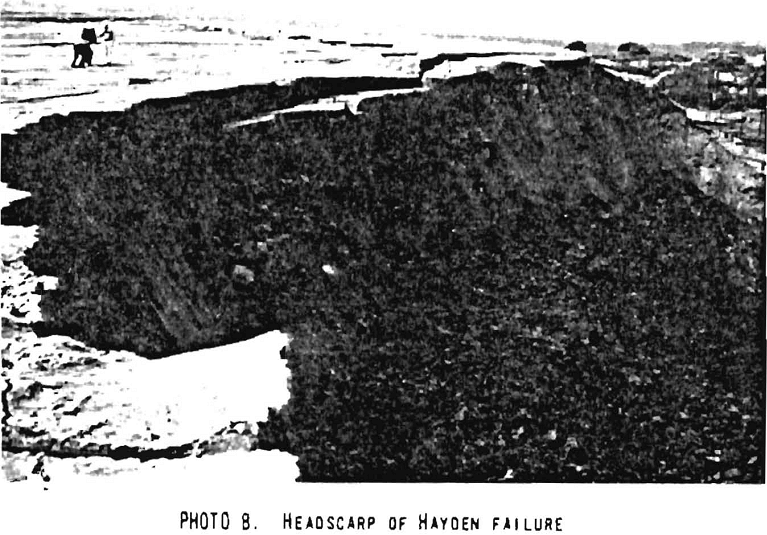
Water from the spigotted materials percolates through the peripheral coarser materials until it reaches the previously deposited much finer-grained tailings. Water then travels horizontally towards the face of the dam and seeps out. This problem was the apparent cause of a failure which occurred near the northwest end of the dam on December 2, 1972. The failure produced a gap in the crest of the dam which measured about 500 feet across, was from 30 to 50 feet deep and extended about 200 feet into the reservoir. A similar but smaller failure occurred the day before our visit, on February 3, 1973, about 1,000 feet east of the previous one. This failure left a gap about 500 feet wide, 20 to 40 feet deep, which extended about 150 feet into the reservoir (Photoplate 1-A). Water was seeping out of the failed portions and active piping could be observed at several points near the contact of the sandy and silty tailings.
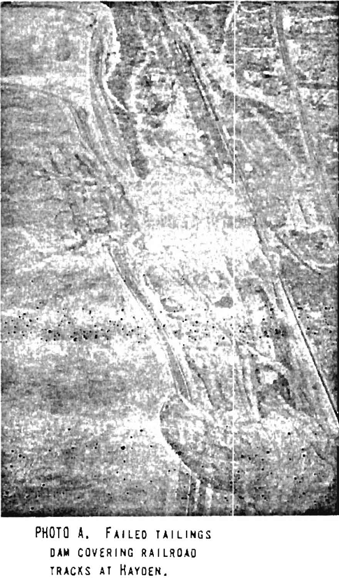
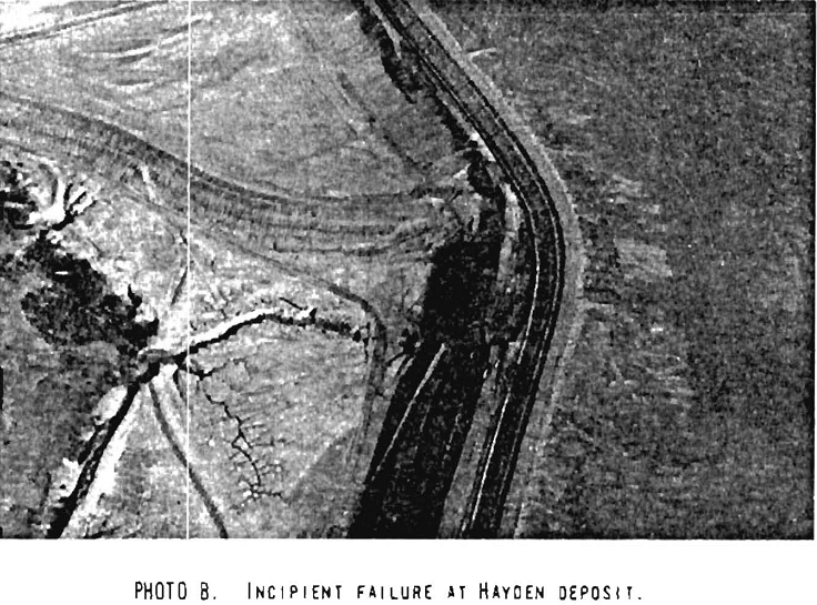
The failures apparently consisted initially of rotational landslides. The failure of last December was apparently followed by a partial liquefaction of the upper 20 to 30 feet of unconsolidated tailings located behind the failed portion. The February failure was not accompanied by liquefaction of tailings (Photoplate 1-B). In the December 2 failure, tailings covered the railroad tracks located near the northern toe of the structure (Photoplate 2-A); fortunately, however, there were no human casualties. Smaller slides and incipient failures could be observed on the ground between both failures. Our aerial inspection also disclosed an unstable area along the western edge of the deposit (Photoplate 2-B) , which was discussed with Kennecott personnel.
The top of the deposit is divided into two ponds by a north-south dike. The eastern, or “A” pond, area was the only one active at the time of our visit, since the western, or “B” pond, area had been affected by the failure and was not considered usable without modification.
A soils sampling and investigation program was begun in the failure areas with the result that new dike construction was set inside the original at considerable distance, thus in effect, flattening the impoundment dike slopes. As the sluffed material has dried out, it is being returned to the original structure and the slope faces dressed up.
Ray Mines is presently developing test plots to determine what vegetation will be suitable for this environment. As suitable plants are determined and the necessary growing procedures developed, the tailings impoundment will be planted to stabilize this dike and reduce windblown dust.
Mission Unit, ASARCO, Sahuarita, Arizona
The Mission Unit of ASARCO, located near Sahuarita, Arizona (Site No. 3, Drawing No. 1), processes copper ore from an open pit mine and began operations in July 1961 at a milling rate of 18,000 tons per day. At present, the milling rate is about 22,500 tpd. The ore minerals consist mainly of chalcopyrite and molybdenite with a grade of 0.70% copper.
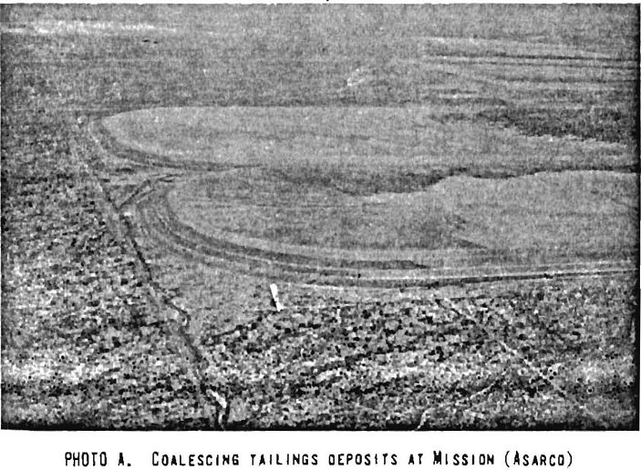
Tailings from the flotation circuit are disposed of in two coalescent tailings ponds covering 740 acres (Photoplate 3-A). The deposit is located about 2 miles northeast of the concentrator and covers a little more than a square mile section. The south dam was built first covering an area of 360 acres and the northern dam covers an area of 380 acres. The south dam was built using hydrocyclones up to 1962. Because of difficulties experienced with this method, the north dam was built using spigots and mechanical lifts. Since 1962, both dams are being raised by spigotting.
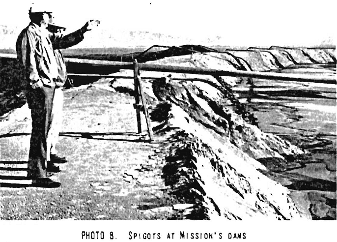
The tailings material is thickened in three 275-foot thickeners to a slurry containing about 50 percent solids and pumped into sump boxes and 24-inch Transite distributing lines. Grade is maintained on these lines by tilted drop boxes 12 feet high and 10 feet in diameter. The last drop box discharges into 20-inch distributing lines which encircle both damp. Every 52 feet, a 4-inch diameter spigot pipe is connected to the 20-inch pipe through a valve. The 4-inch spigot then follows the 1½:1 slope of the dam face, is bent over the crest, and extends outward to discharge tailings into the reservoir (Photoplate 3-B).
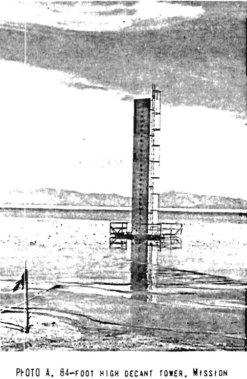
Each tailings dam has a 30-foot high starter dike consisting of compacted fill keyed in some areas to more or less impervious material (Drawing No. 2). The top of each starter dike averages 28 feet in width and represents the initial reservoir filling level. At the time of starter dike construction, the decant system was also installed. The system consists of 84-foot high concrete towers in the center of each pond connected to 18-inch asbestos cement lines cast in concrete which discharge decant water to the clear water ponds located near the toe of both dams (Photoplate 4-A). The tower in No. 2 dam will be raised to 130 feet. The clear water is recycled by pumping back to the mill reservoir.
The crest of each dam is raised by draglines. Each 10-foot vertical lift is at a 1½:1 slope. After three consecutive lifts, for a total vertical height of 30 feet, a new road, 28 feet wide, is established after leveling the top of the dragline-placed material. The 20-inch distributing pipe is lifted to its new position and reassembled. The resultant average overall slope is 3:1. The dragline operates from the crest of the dam, excavates the spigotted sandy material from the reservoir area immediately adjacent to the inside slope of the berm, and places it on top of the berm. A D-6 class tractor is used for leveling and compacting the berm material. In order to avoid settling of slimes in the trench excavated by the dragline when spigotting starts, finger embankments are dozer built in the reservoir area normal to the crest of the dam. These serve the purpose of confining the spigotted tailings in a portion of the excavated trench and permit the sandier, heavier tailings material to push the finer-grained material or slimes out toward the center of the reservoir. Decanted water is extracted through the central decant towers.
Water in the slurry is discharged to the tailings ponds at a rate of 3,000 gpm. Water is reclaimed from the clear water ponds at a rate of about 1,200 gpm, and evaporation rates are estimated by the company personnel at about 1,300 gpm. Consequently, infiltration would be about 500 gpm.
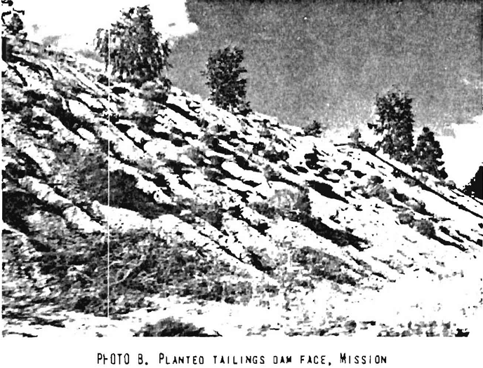
The faces of the tailings dams are being covered with planted native grass and eucalyptus trees as part of a beautification plan (Photoplate 4-B). Native grasses and eucalyptus trees are able to obtain enough water from normal rainfall and nutrients from the tailings material and the alluvial soil used to cover the tailings dam faces. Irrigation is being planned to maintain this vegetation cover during periods of drought.
Pima Mine, Cyprus Pima Mining Co., Tucson, Arizona
Cyprus Pima Mining Company processes ore extracted from their open pit mine adjacent to ASARCO’s Mission open pit mine, about 8 miles northwest of Sahuarita, Arizona (Site No. 4, Drawing No. 1). The mining operations were commenced in 1957 and the present milling rate is 53,500 tons per day. The concentrator is based on a flotation circuit to produce copper and molybdenum concentrates.
The tailings from the flotation circuit are disposed of in two coalescent tailings ponds which cover an area of 1-¾ square miles. The ponds, called No. 6 and No. 7, are built so they will cover one and three-quarter sections, in an east-west direction. Dam No. 6 covers one complete section and dam No. 7 covers three-quarters of the section immediately to the east. Tailings areas 1 through 3 are abandoned and covered with refuse rock from the mine, area 4 is in the process of being covered while area 5, covering about ¼ square mile, is used as in emergency pond. These areas are located adjacent to the concentrator and are about 1 mile northwest of dams 6 and 7.
Dams 6 and 7 were initiated by building starter dikes with local borrow material. These dikes consist of a homogeneous impervious fill placed with minor compaction since the only compaction effort applied was that provided by equipment routing over the fill during placement. The height of the dikes depends upon topographic position and varies from 10 to 15 feet on the southeastern corner of dam No. 7 to about 70 feet on the northeastern corner of the dam. A concrete decant tower placed in the center of each area is connected to a concrete outlet which discharges decant water to a reclaimed-water tank located on the north side of dam No. 7 (Drawing No. 2). The reclaimed water is pumped back to the mill to be reused in the concentrator circuit.
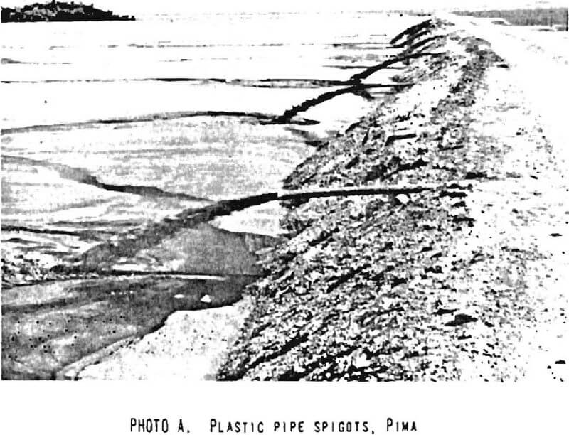
Tailings are discharged to the dams first through a 36-inch, and then through two 20-inch Transite pipes. The slurry is spigotted into the pond area through 4-inch plastic pipes (Photoplate 5-A) attached to the 20-inch Transite distributing pipe. This spigotting method results in a beaching action which keeps decant water away from the crest of the dam and concentrates it around the decant tower.
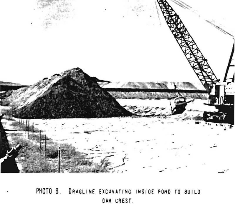
The crest of the dam is raised using draglines. The slopes of the dam are kept at about 14 to 1, and each raise lift is about 15 feet high. After two consecutive lifts, a road is established on the crest of the dam and the next lift is recessed into the reservoir area. The tailings distributing line is then lifted to its new position on the road. The resulting overall dam slope is about 24:1. The draglines operate from inside the reservoir area and advance on a road base built of wood ties placed on top of the sandy, more or less dried out, tailings beach. A trench is excavated with the dragline bucket and the material is placed on the outside edge of the trench (Photoplate 5-B). A dozer levels the pile of material and provides some compaction on the top of the berm.
Tailings slurry is discharged over the raised crest of the dam and falls into the trench. Finger embankments, dozer-built across this trench at regular intervals, confine the spigotted tailings to permit the sandier and heavier portions of tailings material to settle and displace the finer-grained slimes toward the reservoir area.
Water is added to the tailings dams in the slurry feed at a rate of about 10,000 to 11,000 gpm and is reclaimed at about 4,000 gpm. The Company did not have available an estimate of infiltration and evaporation losses.
The outward slopes of the starter dikes are being subjected to a beautification process through planting grasses and other vegetation. The slopes of the abandoned tailing areas exhibit a thick grass and shrub cover, attesting to the success of the vegetation process. The plants are irrigated through a sprinkler system to maintain their growth.
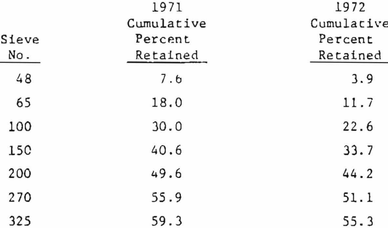
The following table shows, for the years indicated, the average grain-size composition for the tailings material before distribution:
White Pine Copper Company, White Pine, Michigan
White Pine Copper Company, a subsidiary of Copper Range Company, operates the only active underground copper mine in Michigan. The mine is located near White Pine in Ontonagon County, Michigan, within about 4.5 miles of the shore of Lake Superior (Site No. 7, Drawing No. 1). The mined ore consists of siltstone and sandstone containing native copper and chalcocite with an average 1% copper content.
The extracted ore is crushed, ground, and then concentrated in a flotation circuit at a rate of 25,000 tons per day. Mill tailings are disposed of in a newly designed and constructed tailings impoundment (Drawing No. 2), adjacent to the nearby original tailings dam. This original dam, a designed rolled-earth structure, is now nearly full, and is used only under emergency conditions.
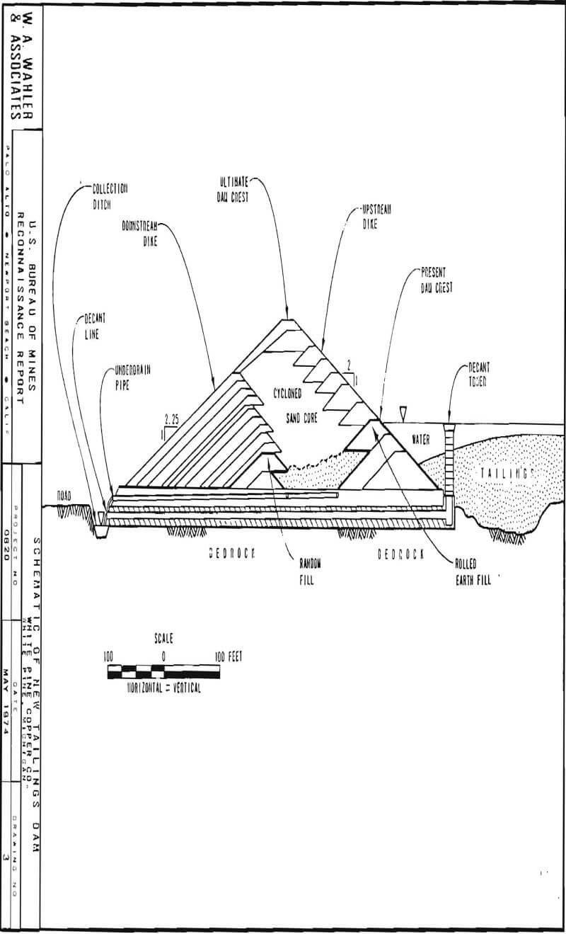
The new tailings dam is being constructed using rolled-earth fill together with tailings sand as embankment materials. Basically, the designed embankment is founded on bedrock and consists of a cycloned mill sand core between two rolled-earth impervious shells (see Drawing No. 3). An extensive underdrain system is intended to keep the sand core dewatered. The embankment, when completed, will have a maximum height of about 125 feet with an upstream slope of 2:1 and a downstream slope of 2.25:1; maximum width at the base will be about 550 feet.
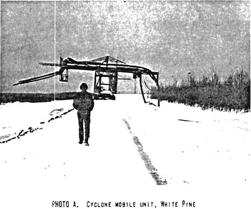
The soil for the earth shells comes from local borrow sources consisting of glacial sediments. The sand for the core is hydraulically transported from the mill to the dam site where it is dewatered by three cyclones mounted on a mobile unit (Photoplate 6-A). The cyclone overflow, at 3 to 10 percent solids, is discharged behind the upstream dike to the reservoir area. The underflow, at 70 percent solids, is deposited as the core be¬tween the upstream and downstream shells. After this underflow material has dried for about three days, it is leveled in place in the embankment by heavy earthmoving equipment. It is then compacted to about 95 percent Proctor with a seven-wheel static type compactor.
The rolled earth impervious shells are raised before placement of, and to contain, the sand core; construction rate depends upon availability of mill sand, annual production level, and climatic conditions. Construction of the embankment is active only in the dry, warm period of the year. In winter, mill tailings are discharged directly into the reservoir without cycloning.
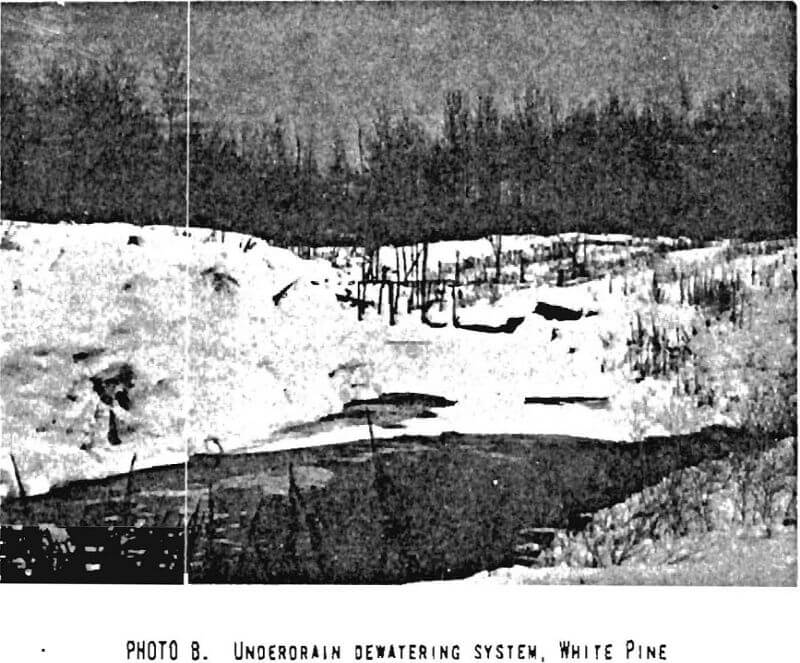
The underdrain system consists of interconnected, perforated pipe underlying the sand core and discharging through unperforated pipes into a collection ditch on the downstream side of the embankment. The underdrain system functions in spite of very low temperatures (Photoplate 6-B). Water levels are monitored through piezometers in the core and indicate that good drainage is being obtained.
The water collected in the reservoir is removed through four 30-inch diameter concrete pipes constructed in bedrock. These pipes pass under the embankment and are connected to four 54-inch diameter reinforced concrete towers located adjacent to the upstream toe of the embankment. Decant towers consist of a series of stacked and grouted-together 8-inch precast concrete rings. The tower is sealed by a circular, galvanized steel lid which has two hinged sides. Clarified water Is moved from behind the upstream embankment into the collection ditch by lifting one or both sides of the lid. Clear decant water is discharged into Lake Superior from the collection ditch.
The roughly rectangularly-shaped embankment has an overall crest length of about 29,000 feet and encompasses an area of about 2,500 acres. It will ultimately contain 14 million cubic yards of borrow material and 10.5 million cubic yards of mill sand. Maximum north-south length is 1.5 miles and east-west length is 2.5 miles. The ultimate storage capacity of the structure is about 280 million tons of dry refuse.
Iron Industry
The iron industry treats ore in a way similar to the copper industry. Gravimetric, magnetic, and flotation processes are used to concentrate the ore and separate the refuse materials. The refuse materials, or tailings, are generally disposed of in tailings areas built according to various methods. Some of the tailings material is used to backfill under ground opening, but most is deposited on surface disposal areas.
Erie Mining Company Hoyt Lakes Plane, Hoyt Lakes, Minnesota
The Hoyt Lakes Plant of Erie Mining Company is located near Hoyt Lakes, Minnesota (Site No. 6, Drawing No. 1), and processes iron ore from open pit taconite mining area;; to produce pellets. The plant produces about 10.3 million dry gross tons of pellets annually from an average processing of 50.0 million gross tons of material. The crude taconite delivered annually to the; mill for processing amounts to about 31 million tons; the additional 19 million tons is waste rock and surface material. On an average daily basin, 28,300 tons cf crude ore are processed each shift, for a total of 85,000 tons per day.
Magnetite represents from 65 to 70 percent of the total iron content of the ore and is the only iron mineral recovered in the concentrator circuit. The crude ore is crushed and ground to approximately 93-94 percent passing the No. 325 mesh. The crushed ore is concentrated from an initial grade of about 31 percent total. Fe to a final grade of about 65 percent total Fe.
The nonmagnetic waste material rejected by the concentrator is combined from different tailings sections of the mill. Reject from the magnetic separator section goes to a hydroseparator for removal of the coarse fraction. This overflow is combined with reject from the finishers and conveyed to the tailings thickeners. The underflow from the hydroseparators is joined by the underflow from the callings thickeners and is pumped to the first pumping booster station at about 40 percent solids.
The tailings disposal area presently consists cf two active basins and is located immediately north of the concentrator. The existing basins cover an area of about 2,400 acres. At present (January 1973), there are about 250 million long tons of material deposited, to which approximately 20 million long tons are added annually. The tailings slurry, with about 35 percent solids, is pumped to the disposal area at a rate of 19,500 to 25,000 gpm. About 78 percent of the water decanted in the basins is reclaimed from the tailings deposit through a return water system and is pumped back to the concentrator for recycling. Tailings material is disposed of in the two adjacent basins identified as Basin 1 and Basin 2. The tailings material has a size distribution which averages as follows:

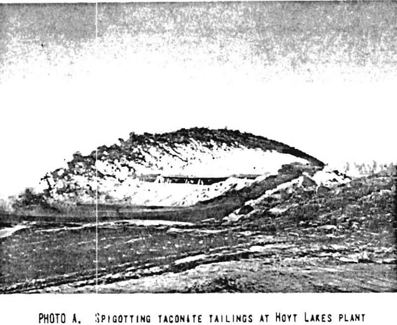
Tailings are transported peripherally around the basins in a 14-inch steel pipe to a 12-inch distribution line which, in turn, feeds 4-inch spigot lines (Photoplate 7-A). When sufficient material has been spigotted in one area, the piping and spigot lines are removed from that particular area, and dozers push the coarser and drier tailings up along the edge of the basin to form a peripheral, dike. The coarse material that settles out first is nearly free draining and dries very fast. The finer material flows toward the center of the basin and the water pond. Each lift of material that constitutes the containing peripheral dike reaches a height of about 20 feet, on a back slope constructed at 2:1. Benches 20 to 50 feet wide separate consecutive lifts so that the average back slope of the entire deposit is about 4:1. The present maximum embankment height is about 105 feet (Draiwing No. 2).
No special procedure is used to compact the material of the peripheral dike, other than the dozer passes made while pushing coarse material to the edge. A continuing program of slope protection utilizing various grasses and legumes is being implemented and has been generally quite successful. Some flat areas in the interior of the basins are also being vegetated for wind erosion protection.
The tailings deposit lies mostly on glacial till which reaches a thickness of up to 40 feet and overlies bedrock. The deposit was initially built with starter earth embankments placed on glacial till after stripping all organic matter and swampy soil. Drains are provided by placing a 12-inch perforated steel pipe around the periphery of this starter dike and about 20 feet inside its toe. Outlets in the 12-inch drain pipe were provided at 300-foot spacings.
The tailings basin deposits have not been subject to any failure. Noticeable erosion features on the frontal slope of the deposits consist of gullies produced by running water either from broken tailings discharge lines, rain, or snow malt. These features are continually being repaired by maintenance crews and are reduced to a large extent by the revegetation program. No evident signs of instability were noted.
Groveland Mine, The Hanna Mining Company, Iron Mountain, Michigan
The Groveland Mine operations of Hanna Mining Company are located near Channing, Michigan (Site No. 9, Drawing No. 1), and consist of a 350- foot deep open pit iron mine, a concentrating plant, and an agglomerating plant which produces iron pellets. The ore body consists of an almost vertically dipping iron formation which contains magnetite and hematite, with a grade of about 35 percent total iron.
The ore is extracted from the mine, crushed, ground, and then concentrated with flotation circuits and magnetic separators. The plant has a rated capacity of 14,300 tons of ore per day. Operations are planned for a period of 30 years at 5 million tons per year. Mill tailings are disposed of in tailings basins located to the south of and adjacent to the mill.
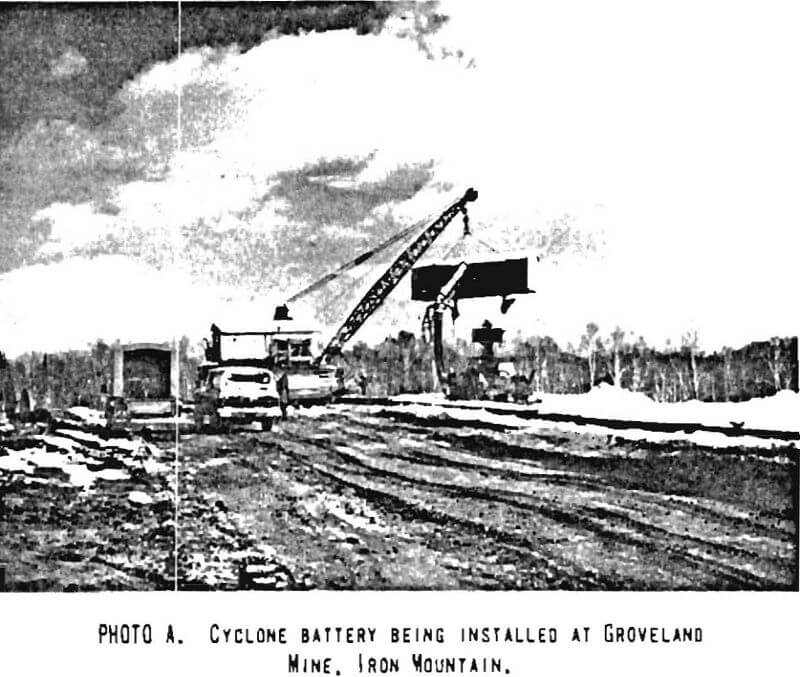
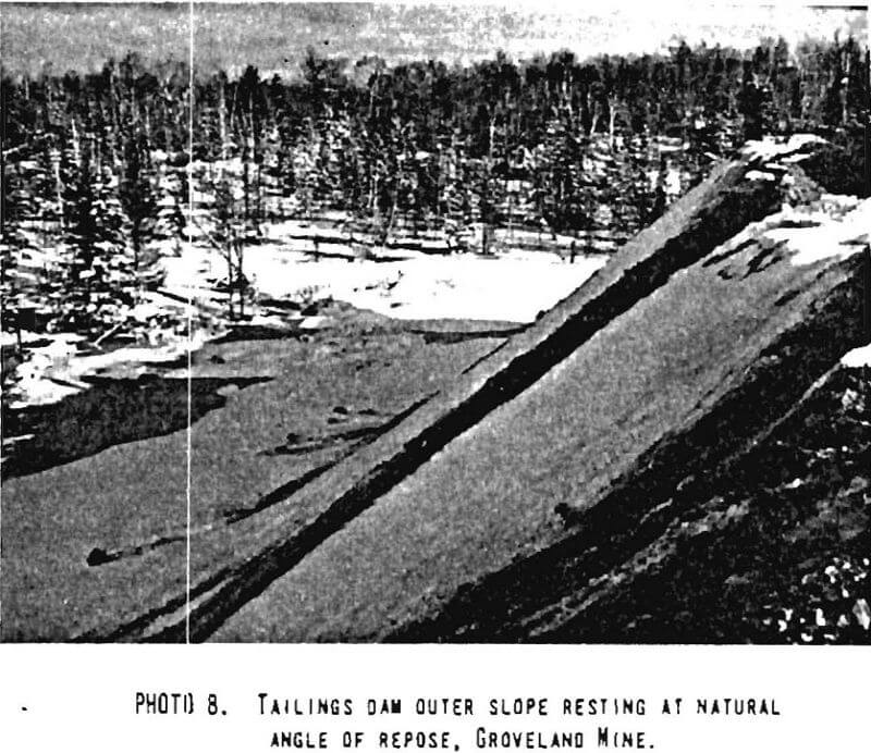
The tailings are discharged through pipelines into three reservoirs formed by dikes constructed by dumping cycloned tailings and spreading them with dozers. Tailings are discharged into the reservoir at a rate of about 9,300 tons per day. Part of this quantity is sandy cycloned material used to build the dikes. One dike, under construction at the time of our visit, was being built using a battery of fourteen 10-inch cyclones installed in a shed which was suspended from a track-mounted crane (Photoplate 8-A). The cyclone underflow fell on the natural ground which had been previously cleared of most vegetation, and the fine-grained overflow was discharged into the reservoir. The dumped material was spread with a bulldozer to form a horizontal roadway, about 50 feet wide and about 60 feet above the more or less flat-lying ground. The material pushed to the sides of this embankment remains at a slope of about 1:1 (Photoplate 8-B). No special compaction effort was being performed other than the dozer passes and the traffic of maintenance vehicles.
Water decanted from the tailings slurry flows into decant towers and thence to decant lines that pass under the embankments and finally to a collecting pond downstream of the three tailings impoundments. A pump station removes some water from this pond for recycling in the mill; the excess water is released to the natural drainage.
One feature observed during our visit was the sloughing of the toe of the dike being constructed. This was apparently due to water moving through the embankment and producing a piping effect at the toe of the embankment. However, no slope failures have been observed as a consequence of this, according to the mine representatives.
Pilot Knob Pellet Company, Ironton, Missouri
Pilot Knob Pellet Company operates an underground iron mine, a concentrator, and an agglomerating plant near Ironton, Iron County, Missouri (Site No. 10, Drawing No. 1). The mine production is rated at about 2,000,000 tons of ore per year. The concentrator plant has a rated feed capacity of 5,780 tons per day.
The mill tailings are separated into coarse- and fine-grained components. The coarse tailings come from magnetic cobber rejects through a hydro- separator and then are dewatered and deslimed by a spiral classifier. The coarse-grained tailings are used to backfill the abandoned underground mine workings. The fine-grained tailings are disposed of at a rate of 700,000 tons per year in a reservoir formed by a specially built earthflll dam.
The tailings dam consists of a 40-foot high rolled-earth embankment of homogeneous section with both upstream and downstream slopes of 3:1 (Drawing No. 2). The embankment is keyed into bedrock, has an upstream blanket drain, and a sand toe filter. A 1,200-foot long emergency spillway is cut Into rock on the left abutment.
The fine-grained tailings enter the reservoir at the extreme upstream area. Clear decant water accumulates towards the upstream slope of the dam and is pumped out from a pump station near the right abutment. The water is pumped back to the plant for recycling.
The tailings dam and reservoir will be filled with material in 20 years according to present operation plans. No abandonment plans were available at the time of our visit.
Lead and Zinc Industry
As in the copper and iron Industry, lead and zinc ores are concentrated by flotation methods. Since the lead and zinc are often combined in a single ore, liberation of the different minerals by selective flotation must be achieved. In many cases this requires additional grinding of bulk or rougher flotation products. The milling process produces refuse materials which are disposed of in tailings dams. In general, the tailings dams are not as large as those in the copper and Iron mine areas, but they share the same type of problems.
Fletcher Plane, St. Joe Minerals Corporation, Bonne Terre, Missouri
St. Joe Minerals Corporation operates several mines and concentrator plants in the Oza-rk Hills of southeastern Missouri. Main products are lead and zinc, and some copper concentrates. Sulfuric acid is produced at the smelter. The ore processed is extracted from underground mines located mainly along the “New” Missouri Lead Belt and occurs mainly in dolomites of the Bonne Terre formacion of Upper Cambrian age. Stratification of the sedimentary rocks is almost horizontal and the ore occurs as disseminated sulfide replacements. Mineralization consists mainly of galena, with minor amounts of sphalerite, chalcopyrite, marcasite, and pyrite.
The ore extracted from the mines is crushed underground and then ground to finer sizes in the surface mills. The finely ground material then passes through flotation plants where it is concentrated to commercial values. The mill tailings from this operation are disposed of in specially prepared tailings basins developed by blocking valleys with dams built of natural soil materials and tailings.
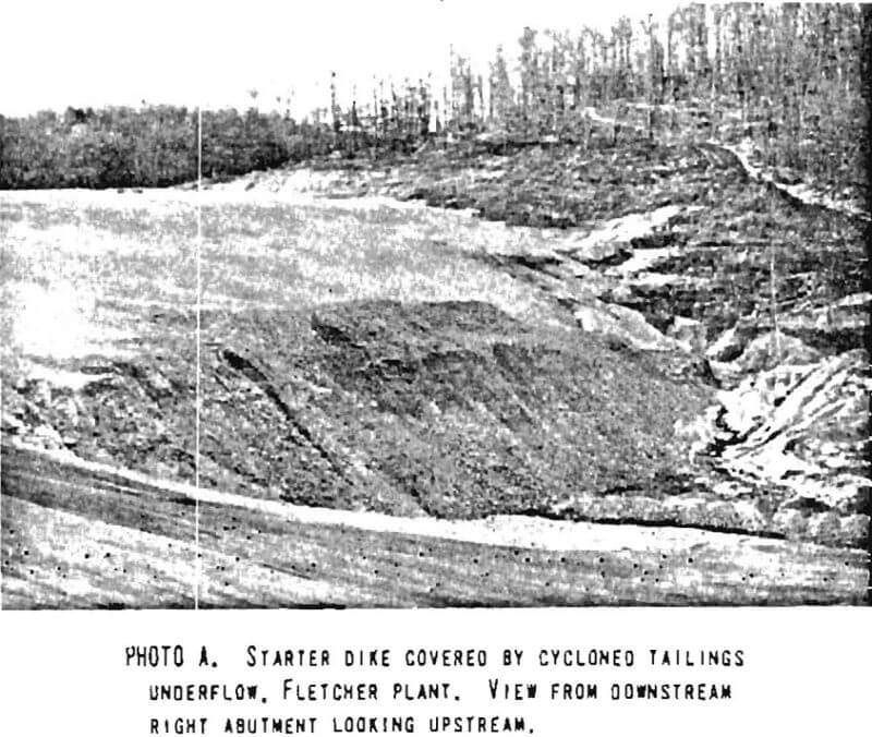
The tailings disposal area visited during this reconnaissance level investigation is adjacent to the Fletcher Plant, located about 12 miles south of Bixby, Missouri (Site No. 13, Drawing No. 1). The designed tailings retaining structure consists of a 30-foot high waste rock starter dam covered by cycloned tailings (Photoplate 9-A). Six-inch to eight-Inch pipes underlie the embankment and act as drains. An emergency spillway is cut at an appropriate place into bedrock. Decant water is recycled and there is no effluent from the tailings pond other than a small amount of seepage. As shown on Photoplate 9-A, finger drains extend downstream from the toe of the starter dam to handle seepage water.
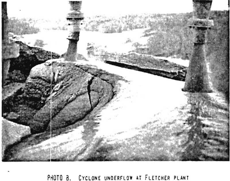
At Fletcher, a special cyclone-carrying rig was designed to deposit tailings over the centerline of the starter dam. Cyclones (Photoplate 9-B) were mounted on a former concentrate haulage trailer which is moved at regular intervals on the roadway formed by the coarse underflow. Progress on this roadway is made in 8- to 10-foot long horizontal steps and sections of pipe are added to the feed line as the tailings pile grows. Fine solids from the cyclone overflow are discharged into the reservoir through a large rubber hose.
The cyclones are fed with mill tailings from a circular manifold In the center of the cyclone cluster. The fine-grained overflow is gathered in an outlet manifold also in the center of the cluster. Valves in the inlet lines allow individual cyclones to be shut down while others are in operation. This permits control and direction of flow either downstream, upstream, or to the center, or any combination desired to distribute the underflow.
The coarse tailings underflow is not compacted by any type of machinery, so that the tailings flow to attain their natural angle of repose. Tailings are spread by dozer to make a roadway for the mobile cyclone unit; this roadway constitutes the crest of the embankment at any given time.
Magmont Mines, Cominco American Incorporated, Bixby, Missouri
The Magmont Mine is located near Bixby, Missouri, in the New Lead Belt of the Ozark. Hills of southeastern Missouri (Site No. 12, Drawing No. 1). The Ozark Hills are only a few hundred feet high but steep and heavily wooded. The ore body at the mine consists of lead, zinc, copper, and silver minerals contained In the almost horizontal dolomite beds of the Bonne Terre formation. The mine is at a depth of about 1,200 feet.
After primary crushing at the mine level, the ore reaches the surface where it is further crushed, ground, and concentrated through a flotation process in the mill. The capacity of the concentration plant is 4,200 tons of ore per day and the daily products are about 380 tons, or 9 percent, of lead concentrate, 42 tons, or 1 percent, each of zinc and copper concentrates, and 3,740 tons, or 89 percent, of refuse material.
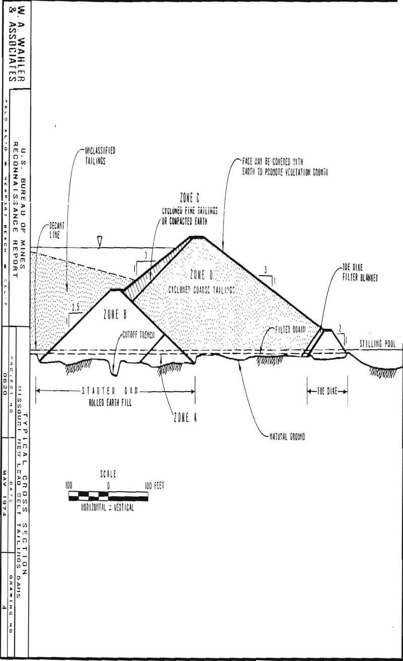
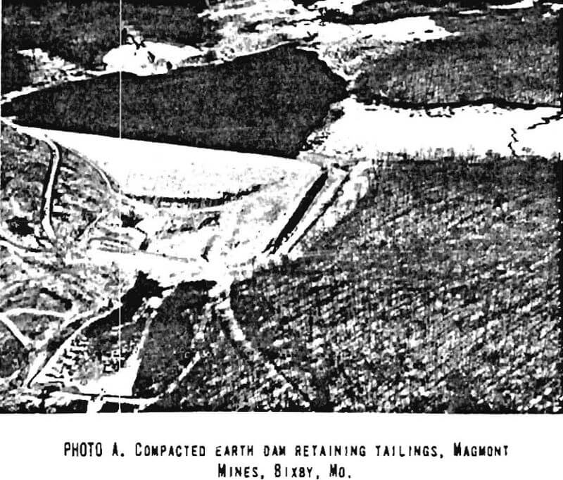
The refuse material consists of fine-grained mill tailings which are disposed of in a tailings impoundment located about one mile southeast of the plant site. Tailings flow by gravity in a pipe into the 80-acre reservoir formed by blocking the mouth of a canyon with a compacted earth dam (Drawing No. 2). This structure is about 1,000 feet long at the crest and up to 85 feet high (Photoplate 10-A), and was designed similarly to the St. Joe Minerals’ Fletcher dam. The basic design features are shown in a sketch in Drawing No. 4. The starter dam was completed during the first 3 months of 1967.
Tailings are presently discharged in the extreme upstream area of the reservoir. Clear water collects near the upstream side of the dam and is discharged into the stilling pool through a 42-inch diameter reinforced concrete decant pipe running under the dam and up an adjacent ridge. This decant line is cast on, and anchored to, bedrock.
An underdrain system consists of 6-inch diameter perforated Transite pipe embedded in gravel. The 6-inch pipe discharges into two 8-inch perforated Transite pipes which lead, on both sides of the 42-inch decant line, to the stilling pool on the downstream side of the toe.
An unlined emergency spillway with a concrete entrance structure is cut into undisturbed soil on the left abutment of the dam to handle flood waters during construction and until tailings fill in the space between the starter dam and the toe dike to raise the dam elevation. A definitive spillway is to be cut across a ridge on one side of the reservoir.
AMAX Lead Company of Missouri, Boss, Missouri
AMAX Lead Company of Missouri is operating the AMAX-Homestake Lead Mine-Mill and Smelter Complex located near the town of Boss, Missouri (Site No. 11, Drawing No. 1). The principal products of this complex are lead and zinc concentrates, refined lead, sulfuric acid, and minor amounts of copper matte and silver bullion. The ore from which these metal pro¬ducts is obtained is part of the “New Lead Belt” of southeastern Missouri. The mine production level is at a depth of about 1,200 feet.
After primary crushing underground, the ore reaches the surface where it is further crushed, ground, and concentrated in a flotation process. The capacity of the plant is about 5,200 tons of ore per day. About 88 percent of the ore is wasted in the concentration process and is disposed of at a rate of about 4,600 tons per day.
The refuse consists of fine-grained mill tailings which are deposited in a tailings impoundment located in a valley close to the mill. Tailings flow by gravity into a reservoir formed by blocking the mouth of a canyon with a compacted earth dam.
This structure, presently under construction, is similar in design to the dams at St. Joe Minerals and Cominco American, Inc. The basic design features are shown in Drawing No. 4. The tailings dam embankment will be about 1,450 feet long at the crest and about 140 feet high when finished. The starter dam, a rolled earth embankment, is about 85 feet high.
Tailings are presently being discharged in the upstream end of the reservoir, and during construction are also conveyed by a gravity flow pipeline to the cyclones located near the crest of the dam at the left abutment. Coarse tailings from cyclone underflow fill the area between starter dam and toe dike. When tailings reach within about 5 feet of the top of the toe dike, they are spread with dozer. In preparation for placement of run-of-creek gravels used to raise the toe dike in about 10-foot increments. The starter dam or frontal slope is raised in a like manner with compacted soil. Exposed slopes and the crest will be covered with compacted soil and seeded to establish a vegetative cover.
Clear water is decanted from the reservoir through a 36-inch diameter concrete pipe, the top opening of which is raised in 5-foot increments. This line Is embedded In reinforced concrete under the embankment, discharges into the stilling pool, and from there to the natural drainage.
Underdrains consist of 6-inch diameter perforated galvanized Iron pipes embedded in gravel. These discharge into 6-inch perforated galvanized iron pipe on both sides of the decant line and finally into the stilling pool.
A definitive lined spillway cut through a ridge into bedrock near the right abutment will be completed when the ultimate embankment height is reached.
The reservoir capacity will be about 30 million tons of tailings material. At present, abandonment plans contemplate completely plugging the decant line and leaving a small lagoon and a tailings meadow or a large shallow lake for recreation.
New Market Unit, New Market, Tennessee
New Market Unit, part of the Tennessee Mines Division of American Smelting and Refining Company, operates an underground zinc mine and a concentrating plant near New Market, Tennessee (Site No. 14, Drawing No. 1). The ore being mined consists of sphalerite in dolomite and averages about 3 percent zinc. The ore is extracted, crushed, ground, and finally concentrated through flotation, at a rate of about 3,200 tons of ore per day. The tailings from the mill are pumped to a tailings impoundment. At present, tailings are being delivered to a new disposal site which consists of a narrow valley closed in three areas by starter dikes (Drawing No. 2).
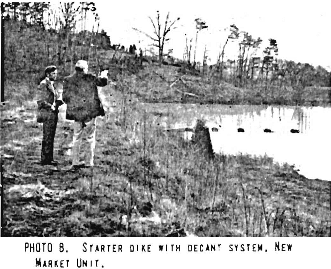
The starter dikes consist of shale and clayey soil borrowed from the adjacent hills and placed by earth-moving equipment with little compaction. A 24-inch diameter corrugated metal pipe underlies the main starter dike and connects a decant tower inside the reservoir area to a clear water pond located at the toe of the dike. Clear water from this pond is pumped back to the mill circuit.
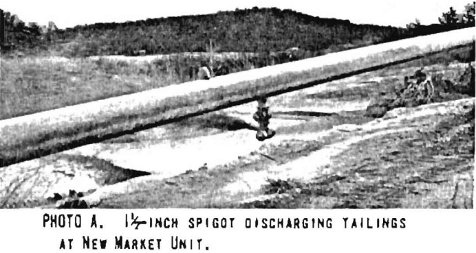
Tailings are discharged through five 1½-inch diameter spigots (Photoplate 11-A) directly into the rear part of the reservoir area at a rate of 130 to 140 tons of solids per hour in a slurry at 25 percent solids. Decant water and slimes collect against the upstream slope of the main starter dike (Photoplate 11-B). Future plans call for extending the tailings conveyance pipe to the top of the starter dike in order to initiate discharge of material through spigots from there. This will commence the upstream method of tailings dam construction. The present decant tower and outlet will be plugged and replaced by another similar outlet works at a higher elevation on the left abutment side. The present elevation of the crest of starter dikes is 1,090 feet. Final elevation, when the dam will be abandoned, will be 1,150 feet.
Small cyclones have been used to separate coarse- and fine-grained tailings material. The coarse-grained portion is being used to build roadways around the right side of the impoundment area, while the fine-grained portion is discharged to the reservoir.
The natural ground on which the tailings dam is being constructed consists of shale and carbonate rocks on which a reddish clay soil and karst topography have developed. Several sinkholes existing in the area have been filled and plugged with tailings material.
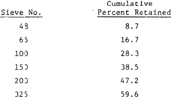
Tailings characteristics used for design of the structure are: 2.8 specific gravity and 20 cubic feet of tailings per ton of material. A typical grain-size distribution of tailings material is:
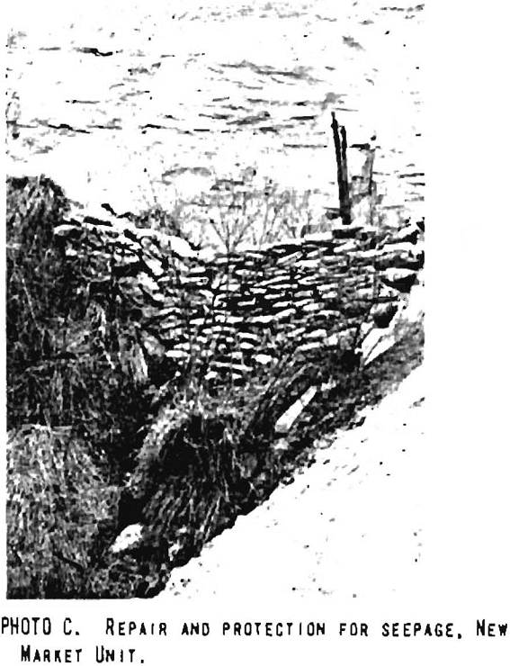
A tailings dam used until about mid-1974 is adjacent co and southwest of the new tailings disposal site. This old dam is about 120 feet high and has 20 to 30-foot wide benches at about 30-foot vertical elevation intervals. The slope between benches is about 1½:1. The deposit exhibits minor gullying from rain erosion. Active piping was observed at the southernmost toe, which is also the lowest point, of the structure. This seepage must have been occurring for a long period, since a wall of concrete sacks (Photoplate 10-C) has been built as a means of repairing the oversteepened area that is failing. Seepage occurs about 30 feet above natural ground elevation and apparently coincides with the crest of an impervious starter dike now partially covered by tailings. No other seepage areas were encountered during this visit, nor were any other reported by mine officials.
Water from the clear water pond, in excess of that necessary for the mill, is discharged into the natural drainage through a reinforced concrete pipe that passes from the pond and under the starter dikes to discharge directly into a creek.
Some parts of the deposit have been rained and sold as an agricultural product. These portions appear from a distance as slide scars or erosion features. No instability that could be attributed to the mining activity was evident around those areas.
Phosphate Industry
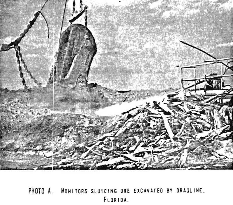
The mining industry in Florida deals mainly with the extraction and processing of sedimentary phosphate ores. This industry is best represented in Polk County where about 10 companies operate about 15 mines. The mining process is a relatively simple one in which large draglines excavate the soft gravelly sand overburden, 10 to 40 feet thick, to uncover the phosohate ore or matrix, an average of 20 feet thick, which is underlain by limestone. The ore is also extracted by dragline and sluiced by monitors (Photoplate 12-A) into pipelines which carry the slurry to a treatment plant. Separation of ore from waste material is done through screening, washing, and differential flotation. Some plants produce only a concentrate while others process the material further to produce elemental phosphorous.
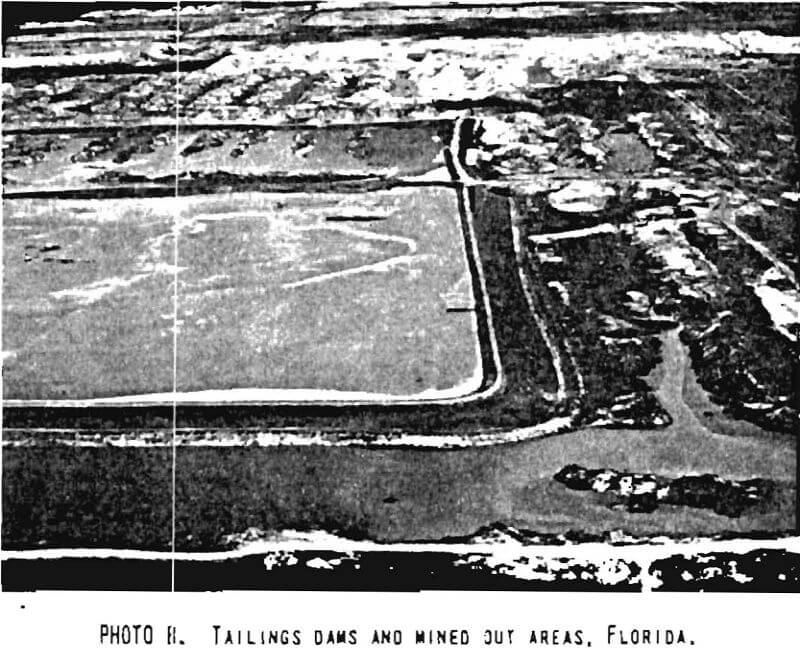
The refuse material or tailings from the concentrator plants consist mainly of sand and slimes. The finest-grained tailings materials or slimes are disposed of by discharging them into specially prepared reservoirs (Drawing No. 2) which cover mined-out areas and are enclosed by embankments built of sandy tailings and overburden (Photoplate 12-B). The tailings-covered areas are reclaimed once the muddy materials have settled to a density sufficient to sustain vegetation or light structures, or to permit recreational use.
The problem shared by all companies working in this industry is the .long time required for the clayey tailings material or slimes to consolidate. The slimes have colloidal properties and thus settle very slowly. Besides being a problem for disposal, the slimes contain about one-third of the total phosphate contained in the matrix. About 490 million tons of slimes containing about 63 million tons of P2O5 are stored in ponds, to which about 4 million tons of P2O5 are added annually. Therefore, the economic importance of developing; a method to recover the P2O5 is very great.
Since the disposal of slimes constitutes not only a hazard because the dams containing them may break and pollute water courses or damage property, but also contain considerable amounts of phosphate, both the mining industry and the Federal Government have joined efforts to find solutions to the problem. The Florida Phosphatic Clays Research Project was implemented as a joint venture of the phosphate mining industry in Florida and the U.S. Bureau of Mines. The purpose of the project is to develop alternative methods of disposal including the recovery of water and P2O5 values from the slimes. Investigation on the consolidation of clay particles in colloidal suspensions, on methods to overcome electrostatic effect of particles, on the effect of mixing slimes with sand tailings and overburden to accelerate settling rates, and on dewatering of slimes are being carried out by the Tuscaloosa, Alabama, office of the USBM, and by individual mining companies. Coordination of all this effort is provided by Dr. Leslie G. Bromwell, Project Director, who works through the Florida Phosphate Council with the individual mining companies. Financing for this project’s coordination is provided by the mining companies.
The project life is estimated to be 3 years, at the end of which time it is expected that some feasible solutions to the problem will have been found.
Since the methods of mining, ore treatment, and refuse disposal are generally the same throughout the industry, the description that follows of the sites visited is detailed only for the Noralyn Plant of International Minerals and Chemicals Corporation. Information on the other sites visited is presented only where site practices differ from the general practice.
Noralyn Plant, International Minerals & Chemical Corp., Bartow, Florida
The Noralyn Phosphate Operations of International Minerals & Chemical Corp. are located in Polk County, Florida, about 2 miles south of Bartow (Site No. 17, Drawing No. 1). The mine, plant, and disposal area have been active since 1948 and annual production is about 4.5 million tons of phosphate rock. The feed capacity of the concentrator is 33,000 tons per day.
The production of a marketable product from the phosphatic ore entails a washing and flotation process for concentration. About two-thirds of the total 14,000,000 tons of matrix or ore mined every year is wasted in the form of sand tailings and slimes.
The slimes constitute the overflow of primary desliming cyclones, which follow a screening operation which separates plus 16 and minus 16 sieve material. The slimes are discharged from the cyclones at a rate of 40,000 gpm, at 4 to 5 percent solids by weight, and constitute an amount of approximately 4 million tons of solids per year.
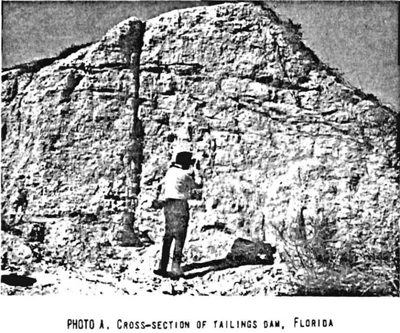
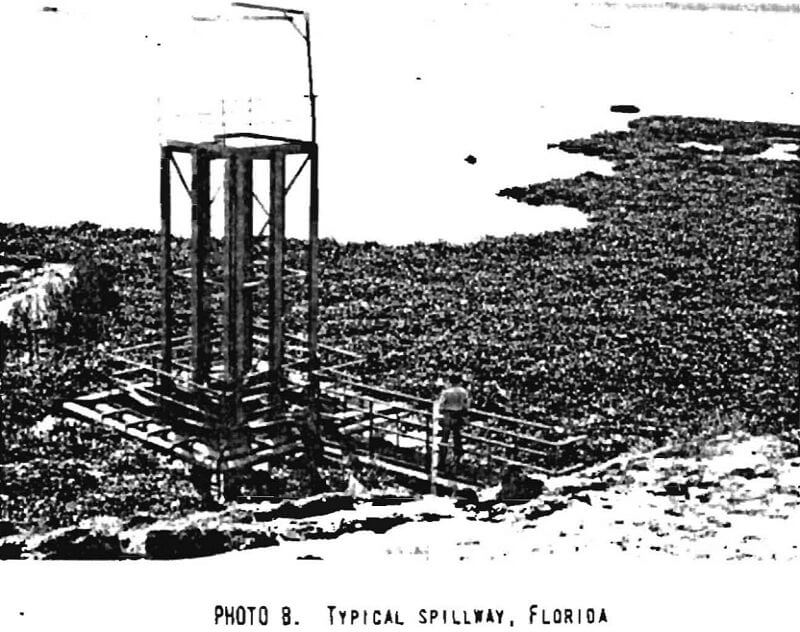
The slimes are pumped into large settling ponds contained by dams constructed around mined-out areas. The existing ponds range in area between 200 and 450 acres each and cover a total area of about 2,000 acres. Dams are constructed of clean sand tailings obtained at a rate of about 5,000,000 tons per year from the flotation process that follows the desliming process, and of overburden without decayable vegetative matter. The typical dam cross section consists of a 30- to 35-foot high homogeneous embankment with upstream and downstream slopes of about 2:1, a crest about 20 feet wide and sloped to the Inside to carry rainfall runoff in that direction (Photoplate 13-A), and occasionally berms on the outer slopes, mainly to reduce erosion. Dams are built with scrapers. Decant towers, or spillways, are used to release clear water to fresh water ponds for recirculation or to nearby streams when necessary (Photoplate 13-B).
The slimes accumulate at a rate of about 16,000 acre-feet/year at 20 percent solids. Every acre-foot of matrix mined produces a volume of slimes of about 1.25 acre-feet. Therefore, construction of new settling ponds is an on-going process.
The slimes have colloidal properties and about 10 percent of the water used in disposal will be retained, even after a settling period of many years. Slimes settle quickly to 10-15 percent solids in the ponds, but even after several years of settling attain only 25 to 35 percent solids.
Reclamation of mined-out land is performed after the slimes achieve about 30 percent solids and a dried-out crust is developed on the surface of the settling ponds. Sand tailings and overburden material are mechanically spread over the surface of the pond to a thickness of a few feet. The reclaimed land is used for agricultural purposes such as orange groves, recreation such as golf courses, or development of light structures, warehouses, etc.
Swift Chemical Company, Bartow, Florida
Swift Chemical Company’s operation in Polk County, near Bartow, Florida (Site No. 16, Drawing No. 1), consists of two mines with their respective concentrators and settling ponds. The combined concentrator capacity is 14,500 tons per day.
About 1971, a pilot program was started by Swift Chemical Company to try to increase the rate of slimes settlement. Slimes were mixed with sandy tailings and pumped into the settling ponds. This appears to cause the slimes to settle faster. Because of production requirements, however, a balance of slimes to sand ratio cannot be maintained. There are times when all the slimes and all the sand tails are mixed together, or when only one material is placed in ponds. The result so far has been that Swift is using less volume for slimes disposal than they would ordinarily generate in the mining operations. In general, the ratio of ore volume to settled slimes volume is about 1 to 1.25. As a consequence, to dispose of slimes in the mined out areas, dams have, to be built. Swift has the ultimate goal of not having to build any more above-ground dams.
Brewster Phosphates, Partnership of American Cyanamid Company and Kerr-McGee Corporation, Bradley, Florida
Brewster Phosphates Haynsworth Mine near Bradley, Florida (Site No. 18, Drawing No. 1), treats ore mined by two draglines. Total ore treated is about 13,000,000 tons per year. The flotation plant has a capacity of 24,000 tons per day of raw feed.
The settling ponds of this operation have slopes of 4:1 on the downstream or outside face of the embankments, and 2½:1 on the inside. The phosphatic clays are discharged into the pond through a 48-inch diameter steel pipe. Sand tailings, sometimes used to reinforce the outside face of the dams, are transported through a 16-inch diameter pipeline.
One of the older settling ponds exhibited plant life typical of what is found in exhausted phosphate waste settling areas. With standing water of sufficient depth (minimum of approximately 1 foot) the common water hyacinth, Eichhornia Crassipes, flourishes. As water depths become more shallow, cattails, Typna Spp, come in heavily and become dominant in “wet” heavy stands of marsh primrose, Jassiaca Peruviana, and marsh flea-bane, Pluchea Foetidissina. In areas of further advanced “drying,” woody species such as willow, Salix Spp., and wax myrtle, Myrica Cerifera, gradually proliferate. Marks, which were observed on the inside slopes of the dam, indicated the top of the dried slimes had settled about 8 feet in two years. The depth of the waste clays was originally about 40 feet.
Monsanto Company, Inorganic Chemicals Division, Columbia, Tennessee
Monsanto Company operates a concentrator, agglomerating plant, and smelter near Columbia, Tennessee, (Site No. 15, Drawing No. 1), to treat phosphate ore and recover elemental phosphorous. The ore is obtained from several open-pit mines in the area. The material wasted as mill tailings consists of extremely fine-grained material of colloidal characteristics. The gradation characteristics of this material are such that a large percentage of it falls in the clay size range. This material is disposed of in a slurry containing about 5 percent solids; as in the phosphate industry of Florida, it takes many years of settling to thicken the tailings to a mud with 40 to 50 percent solids.
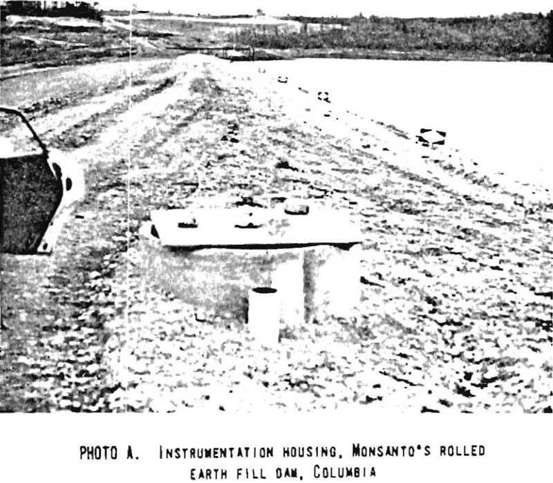
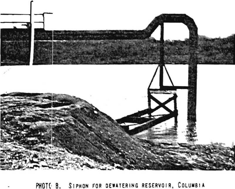
The practice at Monsanto’s Columbia, Tennessee, plant had been to build small ponds. Due in part to environmental problems, and to a lack of available space, the company decided to build a large earthfill dam to contain the tailings in a nearby valley. A structure was designed and is being built in stages (Drawing No. 2). It consists of an earthfill embankment with internal drains and filters which has an inclined impervious core. The embankment has an overall slope of approximately 2½:1, is approximately 150 feet high at the maximum section, will be a maximum of approximately 200 feet high when terminated, and will contain approximately 10,000,000 cubic yards of material. The embankment is instrumented with slope inclinometers, race movement markers, and several hydraulic and gas piezometers to check the piezometric surface (Photoplate 14-A). The reservoir will have an ultimate storage capacity of approximately 45,000 acre-feet and it is estimated that it will contain approximately 25,000 acre-feet of slimes, at an ultimate density of 1,500 long tons per acre- foot or about 76 pounds per cubic foot. Some water from the reservoir is reclaimed through a siphon system (Photoplate 14-B).
Seepage that developed on the face of the dam while the reservoir was being filled with mill slimes was eliminated by sealing the upstream slope of the embankment with consolidated slimes. The clayey slimes deposited in the reservoir and consolidated to a slurry containing 20 to 25 percent solids were pumped out and placed on the interior face of the dam. This procedure stopped the seepage and no problems have been experienced since.
