Table of Contents
The Morenci concentrator of the Phelps Dodge Corporation is a part of the project that was completed after five years had been spent in development of the open-pit mine, equipment and process testing in the former No. 6 concentrator, and construction of the reduction works. The reduction works, of which the concentrator is a part, is about a mile and a quarter southeast of Morenci, on the highway that leads up Morenci Canyon.
Ore
The Morenci ore that is now being treated is a medium-hard monzonite porphyry in which the principal sulphide minerals are chalcocite and pyrite. A minor amount of covellite is present. Chalcopyrite and bornite have been observed under the microscope.
The chalcocite occurs mainly as a coating on pyrite. Some of the coatings are so thick that the pyrite presents the appearance of being an inclusion in chalcocite. Some are less than one micron thick and are barely visible at 500 diameters magnification of a polished cross section. Some chalcocite is present as a dissemination in the gangue.
Primary Crushing
Mine cars contain an average of 85 dry tons of ore. Dumping is against an ore pocket above the grizzly. It is specified to be at the rate of one car every min. A protected concrete wall supports the railroad bridge and divides the ore flow to both sections of the grizzly and to the two sides of the crusher.
No delays of consequence have occurred as a result of coarse rock lodging above the grizzly. The ore contains approximately 3.5 pct moisture and, except when the moisture content is above 5 or 6 pct, the angle of repose in the dumping pocket lies between 40° and 50°. The angle of repose may become as high as 75° when wet ore is received. Alternate receipt of coarse and fine rock then assists in clearing the pocket. Provision was made in the design for the installation of chain feeders above the grizzly, with the object of regulating the rate of feed to the gyratory crusher and increasing the efficiency of the grizzly, but the necessity for them has not arisen. Choking of the gyratory crusher by large rock occurs but jams are easily broken by the use of a collapsible hook attached to a 10-ton traveling crane immediately above the crusher, beneath the top-floor hatch covers. The ore travels across the grizzly rapidly. About 25 pct of the material passes through the openings and this constitutes a major portion of the undersize in the run-of-mine ore. The crusher has ample capacity, so high efficiency of the grizzly is not necessary.
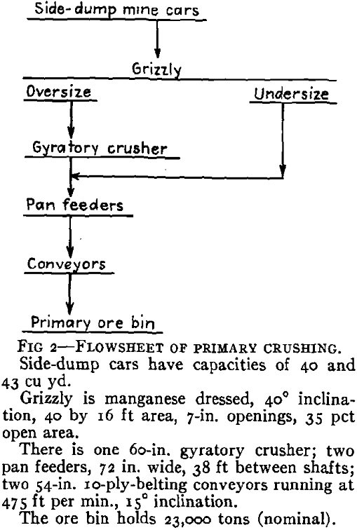
The spill conveyors with which the pan feeders are equipped have been worth the installation cost by saving labor necessary for clean-up work. Auxiliary conveyors to deliver spillage to the main conveyor farthest from the pan feeders have been installed since operation of the plant began.
Secondary Crushing
The secondary crushing plant is unusual in the very compact arrangement of the equipment. It is divided into two principal sections, each including two complete crushing units. One section of two units prepares and delivers ore to the original part of the concentrator. The other section delivers crushed ore to the concentrator extension. One of the two units of this section can deliver ore to either part of the concentrator.
The discharges of the pan feeders pass over finger grizzlies before dropping on the conveyor belts, which are supported at the loading point by impact idlers. The 10-in. size of ore is discharged by the conveyors into ore pockets preceding the grizzlies and the grizzly oversize product passes directly into the standard cone crushers. Two worn manganese-steel ball-mill shell liners are swung over each standard cone crusher to divert the grizzly product vertically downward to the crusher feed plate.
Two systems of 54-in. conveyors deliver the ore to the two secondary ore bins of the concentrator. One conveyor of each series is equipped with a stationary magnet, which collects tramp iron that escapes from the secondary crushing plant. These magnets have been useful in decreasing damage to the feeder belts of the grinding section. One of each series of conveyors is also equipped with a conveyor scale having a remote indicator at the operator’s stand of the shorthead cone crusher.
The collecting hoods are designed to spread the air intake over a large area by the use of conical or pyramidal tops. The entrance of the air into the ducts is at a sufficient distance from the point of greatest turbulence so that only the smaller dust particles enter the ducts. Enough air is drawn into the hoods to prevent exit of coarse or fine dust particles.
Grinding
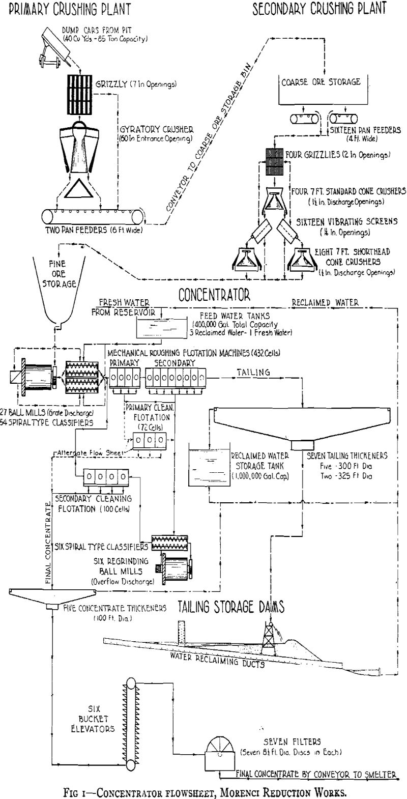
Except for the return of reclaimed water, the concentration processes beginning with grinding (Fig 4) are divided into two separate plants having equipment in proportion to the 16 grinding mills of the original plant and the 11 mills of the extension. Each of the 27 grinding units consists of one grinding mill and two classifiers as principal equipment. Ore for each unit is drawn from the bin through one or more of four horizontal feeder gates and is discharged upon a feeder conveyor driven by a variable-speed direct-current motor. From the feeder conveyor it is transferred to a weighing conveyor, which delivers the ore to the grinding-mill scoop housing. All new feed to the grinding units and the circulating sand load from the classifiers enters the grinding mill through the double-entrance scoop. The central drum-feeder portion of the scoop is used only for the addition of grinding balls.
Conveyor scales weigh the feed to the grinding mills and when set to a desired rate of feed regulate the speed of the feeder conveyors through a series of relays. The scale is electrical in principle and is dependent upon frictional contact at only one point, where an idler resting upon the return portion of the conveyor belt transmits the belt speed effect to the scale head through synchronously acting motors. The scales have met all requirements of accuracy and can be easily tested and repaired.
The unique method provided in the original design for handling grinding balls has been very successful. The balls are unloaded from railroad cars by magnet into overhead bins, from which they flow by gravity through counterbalanced gate spouts to a trailer drawn by a battery truck. Both are designed for rail travel. After being weighed on track platform scales, the truck and trailer travel along a 24-in. gauge railroad running on a platform between the mill- scoop housings and the sand-discharge ends of the classifiers.
Flotation and Regrinding of Concentrate
Distribution of flotation feed that contains 18 pct solids is made by flow from outlets at the same level in the sides of a distributor that contains baffles to assist in mixing the returned cleaner tailing with the new feed. Collector reagent and lime having been added in the grinding process, frother reagents are dispersed in hot water and added to the flotation feed a short distance before it enters the distributor. Additional lime may be added at the same location if it is desired but that is done infrequently because addition to the grinding circuit has been found to be much more effective in controlling the alkalinity.
The mechanical flotation unit develops air for flotation and circulates the ore pulp for aeration by the action of concentric squirrel cages composed of rubber-covered posts. The inner or rotating squirrel cage has impellers at the top and bottom, which oppose each other by pumping into the rotor to force ore pulp out between the rotor posts. A vortex forms in the pulp by the pumping action of the upper impeller, into which air is drawn. The pulp is aerated as the mixture of air and pulp is forced through the openings between the posts of the stator. Probable action of the machine in the production of small bubbles is both by cavitation and by shearing.
Power consumption has been moderate and capacity good during the past four years. The roughing flotation machines are arranged in rows of 12 cells. The first four are the primary rougher machines and 2 ft below them is the secondary rougher machine, containing eight cells. In the original plant there are two flotation-feed distributors, each feeding 10 rows of roughing cells divided into sections of five machines of 12 units each on two sides of the distributors. In the extension plant there are also four roughing flotation sections but each is composed of only four rows of machines.
First operation of the Morenci concentrator was done under a flotation flowsheet chosen during operation of the test concentrator. The primary rougher concentrate was re-treated in primary cleaning machines and the tailing from the latter was united with the secondary rougher concentrate, reground and refloated in secondary cleaning machines. The concentrate made in both cleaning operations composed the final concentrate. The use of that flowsheet, which is designated as alternate in the flowsheet shown in Fig 5, was abandoned as a result of later experiments to increase the grade of the concentrate. The cause was lack of sufficient control of the composition of the primary cleaner concentrate resulting from changes in the character of association of pyrite and chalcocite in the ore.
A 48 pct decrease resulted in the amount of sizes on 200 mesh while the finest sizes increased only by 7.3 pct. The moisture content of the concentrate increased only 2.8 pct.
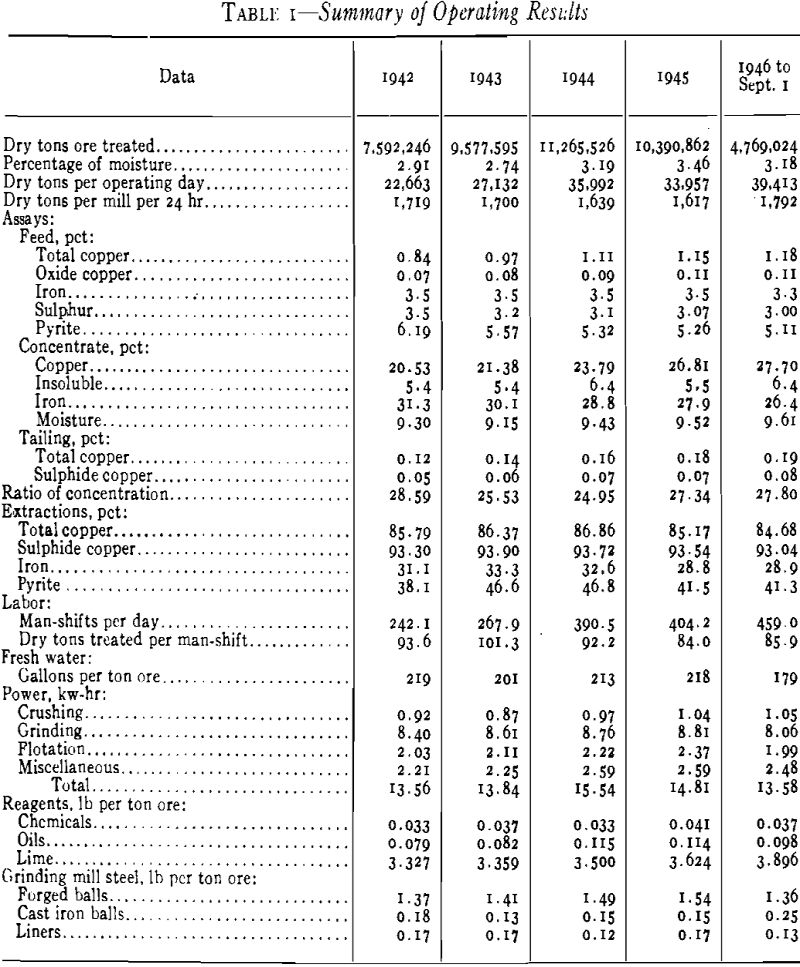
The chemical composition of the concentrate produced in the year 1945 is typical of present practice: copper, 26.81 pct; insoluble, 5.5; silica, 3.8; alumina, 1.4; iron, 27.9; lime, 0.1; sulphur, 38.7; molybdenum sulphide, 0.24; gold, 0.019 oz per ton; silver, 1.109 oz per ton.
Filtration of Concentrate
The filtration flowsheet is shown in Fig 6. Concentrate pulp containing about 20 pct solids is laundered to the thickeners and after thickening to 55 or 60 pct solids is elevated and flows in launders to the filter plants. There are two filter plants, one containing four filters and three rotary vacuum pumps and the other containing three filters and two rotary vacuum pumps.
Two series of belt conveyors deliver the filtered concentrate to the storage beds. Either filter plant can deliver concentrate to either of the two main conveyors by moving a connecting conveyor.
There are two small rotary positive-pressure blowers in each filter plant, which provide air at one pound per square inch pressure for the discharge of the filter cake.
Water Supply and Consumption
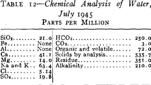
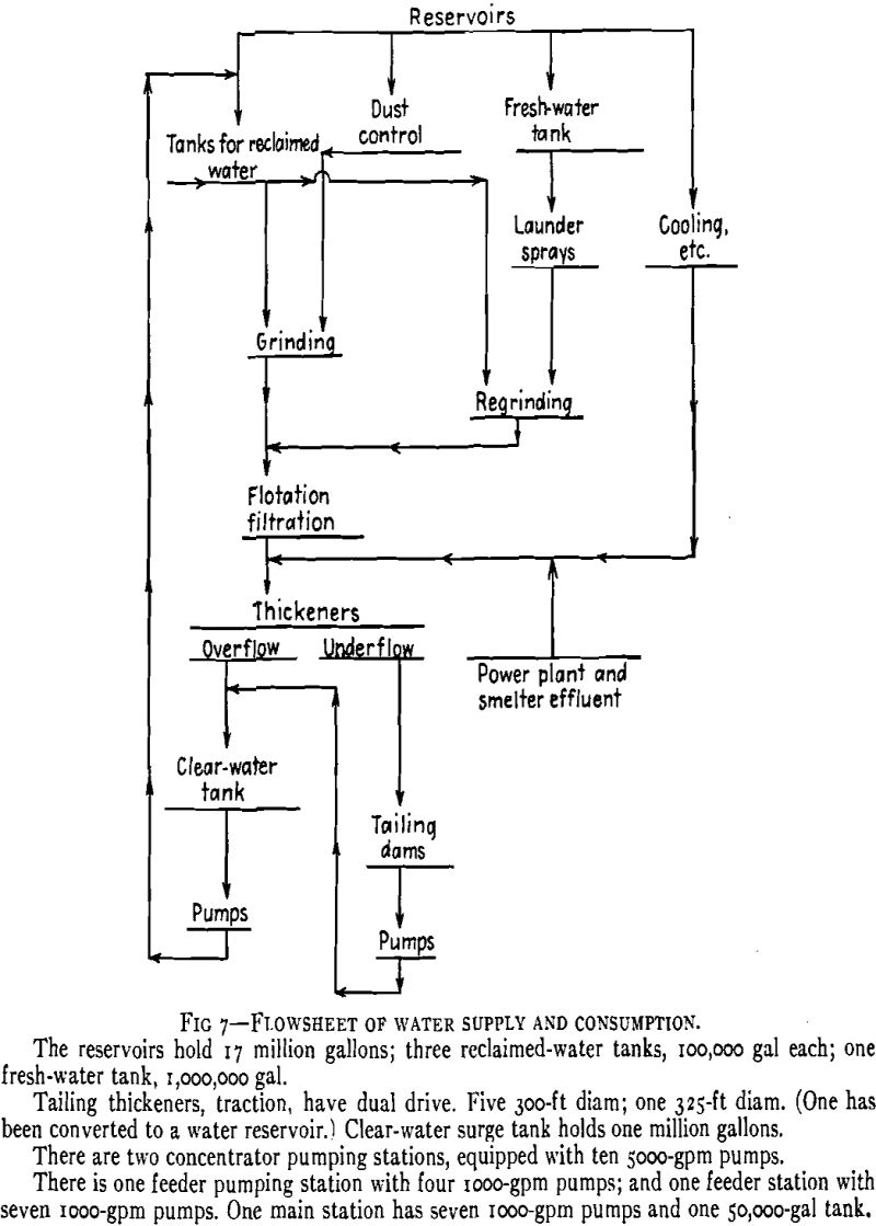
The source of the fresh water supply is Eagle Creek, from which it is pumped a distance of 6 miles against a difference in elevation of 1100 ft. The water has low total solid and chlorine contents, as shown in the typical chemical analysis of the composite sample taken in July 1945.
There are three underflow pipes, each 8 in. in diameter, from each tailing thickener. Pipes from five thickeners converge through a system of tunnels to one discharge or spigot house, and those from the two remaining thickeners end in another house. There are two main-line diaphragm valves on each line under the centers of the thickeners.
Tailing Disposal
The tailing is stored in a wide valley in the foothills south of Morenci. The bottom of the valley is divided into three ravines, the central and widest of which is known as Morenci Canyon. To the west of Morenci Canyon is Stargo Canyon, separated from it by low ridges. Along the east side of Morenci Canyon is a comparatively high ridge traversing the entire length of the tailing-disposal area. A narrow ravine to the east of the ridge has been named East Canyon. All three of the ravines lie on an average slope of 4 pct. The upper parts of Morenci and East Canyons were used for disposal of tailing from the former No. 6 concentrator. The whole area is roughly 3 miles north-south and 1 mile east-west in size. The difference in elevation between the upper part nearest the reduction works and the lowest near the reclaimed-water pumping stations is approximately 700 ft.
Tailing flows to the disposal area through a flume constructed on the ridge between Morenci and East Canyons. The flume is 17,000 ft long and is built on a minimum grade of 1.5 pct and a maximum of 2.5 pct. The average grade is 1.75 pct. The original flume was a curved-bottom launder made of cement-asbestos composition material. Because of wear along the center line of the bottom, the flume is now being sheathed in concrete. The curved bottom was designed to carry small flows without impedance.
If the deposited tailing is dry enough to support a dragline excavator on timber mats, the new bank is built by that method using the deposited tailing. The bank is compacted to a height of 36 in. by an angledozer. A maximum height of 36 in. was chosen for this kind of bank, to avoid the formation of too deep a borrow pit adjacent to the bank. That height has also been found to produce more rapid drying of the deposited tailing than a deeper deposit, because of the limited absorption of moisture by the previously deposited tailing. Divisions are left in the borrow pit at about 200-ft intervals, to decrease the trapping of slimes near the bank. The more rapid overflow from each section washes the slimes toward the pond. If the deposited tailing of which the bank is made is sufficiently dry, the borrow pit is partly refilled by the use of bulldozers, or the pit depth is kept at a minimum by transporting the tailing to the dragline with bulldozers.
As the ducts eventually would become covered with tailing, concrete stacks were constructed with connections to the ducts. They have 10-in. diameter holes on a spiral line around the wall at a difference in elevation of 2 in. between holes. There are nine holes for each turn of the helix. The stacks have an inside diameter of 6 ft and walls 12 in. thick. Several of the stacks are now in use, since some of the ducts between dams have been covered with tailing. Holes in the ducts and stacks are closed with tapered wooden plugs when the tailing level reaches them.

