Table of Contents
This paper is one of a series prepared by the Bureau of Mines on shaft sinking methods and costs in various districts throughout the United States. The Burgin shaft was sunk as part of the exploratory program of the East Tintic project of Bear Creek Mining Co.
The Tintic district is in Utah and Juab Counties in central Utah, about 88 miles south of Salt Lake City. It is one of Utah’s major metal-producing areas and has yielded ores valued at more than $400 million. Many of the mines have been either “worked out” or have been worked to such depths that costs are prohibitive, principally because of excessive pumping of water. The project is interesting in that it demonstrates a trend in exploration that is necessary to maintain and develop future mineral reserves.
Purpose of Mine Shaft
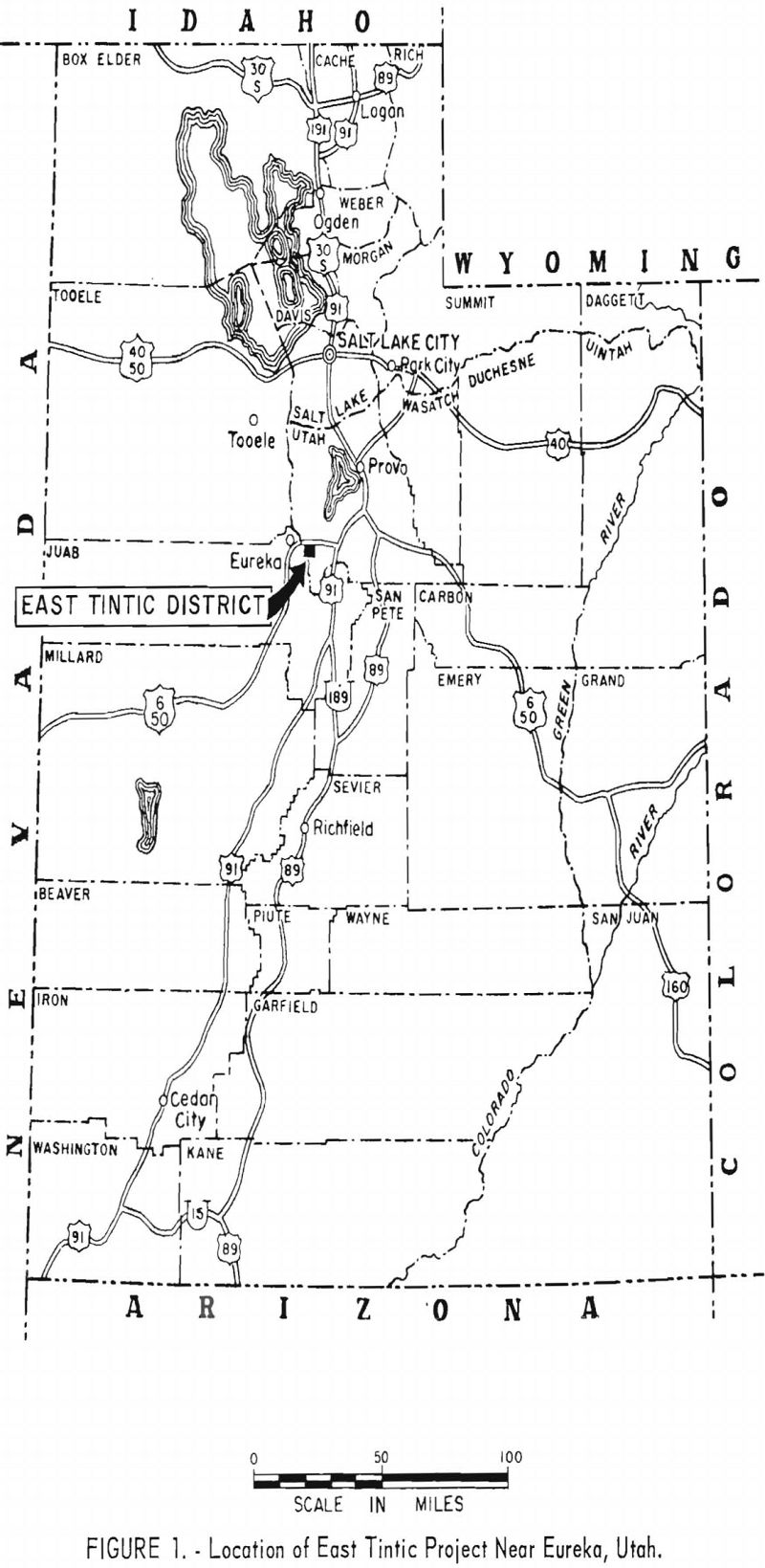
The Burgin shaft was planned to provide access for exploring blind but geologically favorable areas in the East Tintic district, approximately 5 miles southeast of Eureka, Utah (fig. 1). Bear Creek Mining Co. has a long-term lease on several hundred acres of patented and unpatented mining claims in the area. The area was extensively studied before the project was approved; geologic mapping and surface core drilling was done in the early phases of the project. Geologists of the Federal Geological Survey investigated the area and since 1943 have used geochemical methods to study rock alteration.
The objective of the East Tintic project is to find replacement ore bodies in Paleozoic limestone and dolomite beneath volcanic rocks that blanket the area. Studies in the area by the Federal Geological Survey indicate that rock alteration may be a guide to ore deposition. Mineralized limestone east of old mines of the district was found by surface exploratory drilling. Drilling by the Federal Geological Survey and studies of projected geologic structures and patterns of hydrothermal alteration partly determined the areas to be explored by the Bear Creek Mining Co.
The Geological Survey and the mining companies had previously found that surface drilling is inconclusive and unsatisfactory as a means of proving ore in the district. Bear Creek Mining Co. supplemented drilling information by shaft sinking, followed by crosscutting and underground core drilling.
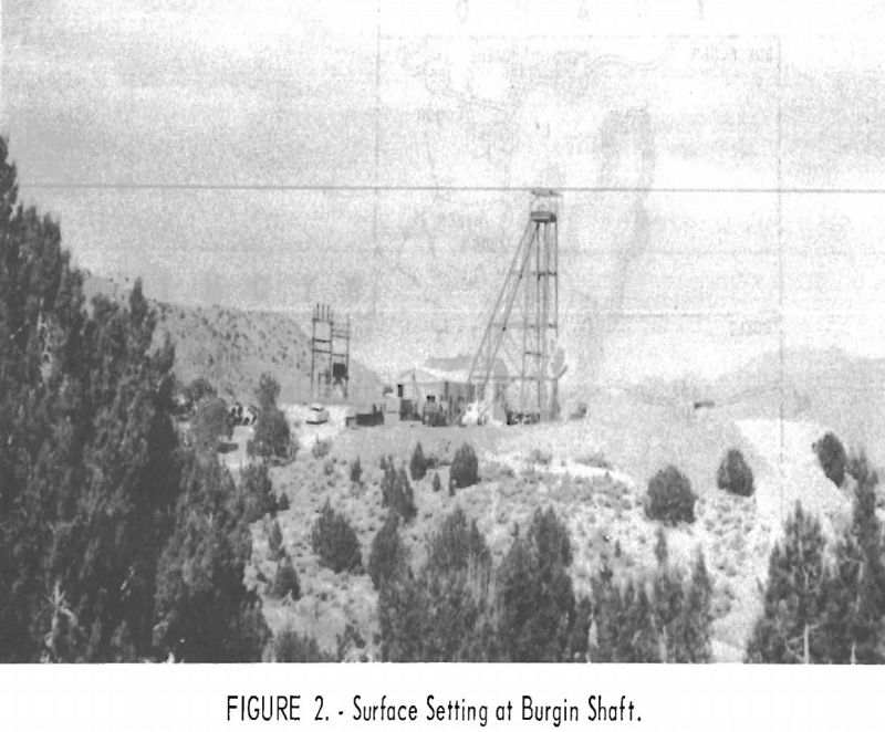
The Burgin shaft (fig. 2) was named for William H. Burgin, Bear Creek Mining Co. district geologist, who was killed in a commercial-plane crash in 1955. Mr. Burgin was responsible for much of the preliminary work on the project.
As the result of competitive bidding by four companies, the contract for sinking the Burgin shaft was awarded to Centennial Development Co., a Utah corporation with offices at Eureka, Utah. Work on the project was begun November 12, 1956, and the shaft was completed to a depth of 1,100 feet, August 1, 1957.
The contract included constructing a hoist and compressor building and a change building and office. It also required installing a hoist, compressor, lamp-charging equipment, water-storage tank, water heater, oil furnace, air receiver, and electrical substation; concreting the collar of shaft, the hoist and compressor foundations, the building slabs, and the headframe foundations; and sinking and timbering 1,100 feet of a 2 ½-compartment shaft; and excavating for a 1,050 level station and loading pocket. The Bear Creek Mining Co. let the contract for fabricating and erecting the steel headframe to another company. Electrical and plumbing work and erection of the aluminum buildings were subcontracted by Centennial Development Co.
In July 1957 a contract awarded Centennial Development Co. included drifting and crosscutting from the 1050 level of the shaft.
Geology and Physical Characteristics of Rocks
The East Tintic district is on the east flank of the East Tintic Mountains. The west part is on the steeper slope of the range, which grades easterly into the broad Goshen Valley. The area has been extensively dissected by stream erosion.
The geology of the district is extremely complex; it comprises folded and faulted Paleozoic sedimentary rocks that, in many places, are covered by Tertiary lavas. In the main Tintic district the sedimentary rocks dip steeply, but in the East Tintic area the dips are more gentle and in places are almost flat. These sedimentary rocks consist of marine limestones and dolomites above the basal Tintic quartzite. The surface in the East Tintic district is covered with Packard rhyolite or other extrusive rocks, but some intrusive dikes of monzonite and quartz monzonite porphyry have been found, both on the surface and underground.
Most of the ores produced in the East Tintic district have been mined from replacement deposits in limestone. The principal ore bodies, containing lead, silver, and zinc, have been found in the Tintic Standard and North Lily mines. Pyritic copper-gold ore has been mined from veins in the underlying Tintic quartzite at these and other mines. The replacement deposits are commonly found in areas of shattered, jasperoidized limestone, usually at the intersections of low-angle faults and minor northeasterly crossfissures.
The physical characteristics of the rocks proved to be almost ideal for shaft sinking. In general, the rocks were hard, massive, and tough, with a minimum of fractures. The abrasive action of the rhyolite accelerated bit wear. Fragmentation after blasting was not as good as that in the limestone and dolomite. Only one major fracture zone was found, and it offered little trouble, except for water seepage. Occasional thin zones of shale and quartzite were noted below the rhyolite. The extremely hard quartzite required about double the average drilling time. Ground support was not a problem.
Shaft Site
The shaft is in the SE1/4SE1/4 sec. 15, T. 10 S., R. 2 W., Salt Lake Meridian, Utah County, Utah, 5 miles by road east of Eureka and 1 mile from the Tintic Standard surface plant at the No. 2 shaft. U. S. Highway 6 passes through Eureka and is 2 miles north of the shaft by road. Gravel and dirt roads provide access to the site. The altitude at the shaft collar is 5,635 feet.
The Packard rhyolite averages 700 feet in thickness and covers the surface. A hole had been churn-drilled near the shaft site earlier, and the geologic log of the stratigraphy for 1,100 feet was determined as follows:

The factors considered in choosing the shaft site include:
(1) Proximity to the exploration targets; (2) probable absence of major faults; and (3) topography suitable for the surface plant.
Shaft Sinking
Centennial Development Co. began work November 12, 1956. Preparation, including sinking the first 55 feet, was done by January 29, 1957. Active shaft sinking was begun January 30 and continued until completed on August 1, 1957. Work was continued on the shaft station and loading pocket and, under a new contract, on exploratory drifting and crosscutting.
Preparation
The preparation began by leveling the surface-plant site with an H.D. 5 diesel bulldozer and laying a 2-inch water pipeline for 5,000 feet between the shaft site and Dividend (Tintic Standard No. 2 shaft). This line was buried 3 feet at the shaft site and below the roads and railroad crossings but otherwise was laid on the surface. Surface excavations were made for building and equipment foundations and for pipe and electrical conduits. The surface-plant layout is shown in figure 3.
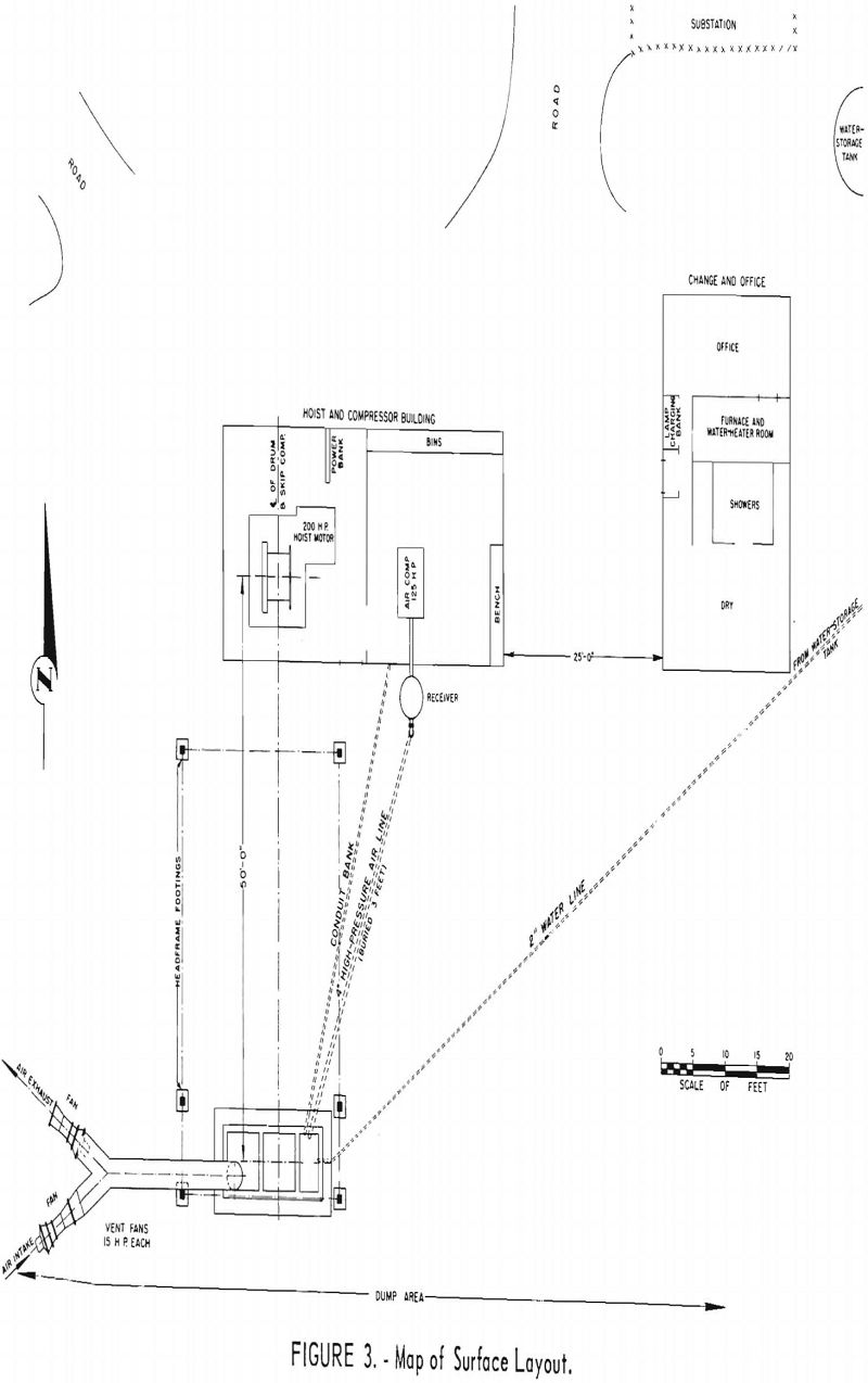
Insulated aluminum buildings were erected by a subcontractor to house the hoist, compressor, electrical panels, changehouse, and office. The installations for a 10,000-gallon water-storage tank, fuel-oil tank, septic tank, furnaces, waterheater, and heating equipment were also subcontracted. Concrete (5½ sacks of cement a cubic yard) was transported 35 miles from a ready-mix plant in Spanish Fork, Utah. All concrete work contains reinforcing steel and was handled by the regular crew.
All electrical work was performed by subcontractors, including erection of a 750-kv.-a. outdoor substation. The electrical distribution system includes a 480-volt surface circuit, a 4,160-volt underground feeder, and a hoist signal arrangement; a 4,160-volt circuit breaker and control panel were installed in the hoist house. A charging panel for 15 lamp batteries was placed in the changehouse.
A single-drum hoist 4 feet in diameter and 3½ feet in width is powered by a 440-volt, 200-hp., a. c. motor. The wire rope for the hoist is 1 inch in diameter and 1,536 feet in length. The maximum rope speed is 800 feet per minute. The air compressor has a rated capacity of 686 c. f. m. and is powered by a 440-volt, 125-hp. motor; it is in the room adjoining the hoisting installation and connected directly to an air receiver with a volume of 97 cubic feet. Air pressure is maintained at 110 p. s. i.
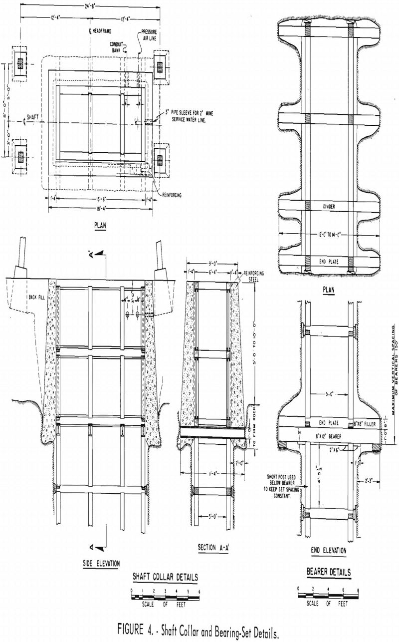
The shaft was sunk 55 feet with the aid of a ½-cubic-yard dragline shovel. The shaft collar was concreted to solid rock where the first bearing set of timber was installed. Concrete was placed 2 feet thick at the base and 1 foot 4 inches at the top (fig. 4). A 50-foot steel headframe was fabricated at Grand Junction, Colo., and required 4 days for erection. The sheave wheel is 4 feet in diameter. The center of the shaft is 50 feet from the center of the hoisting drum. The wire rope was connected directly to the 66- by 44-inch bucket. A crosshead cage designed by the company was supported by a torpedo clamp on the wire rope 8 feet above the sinking bucket.
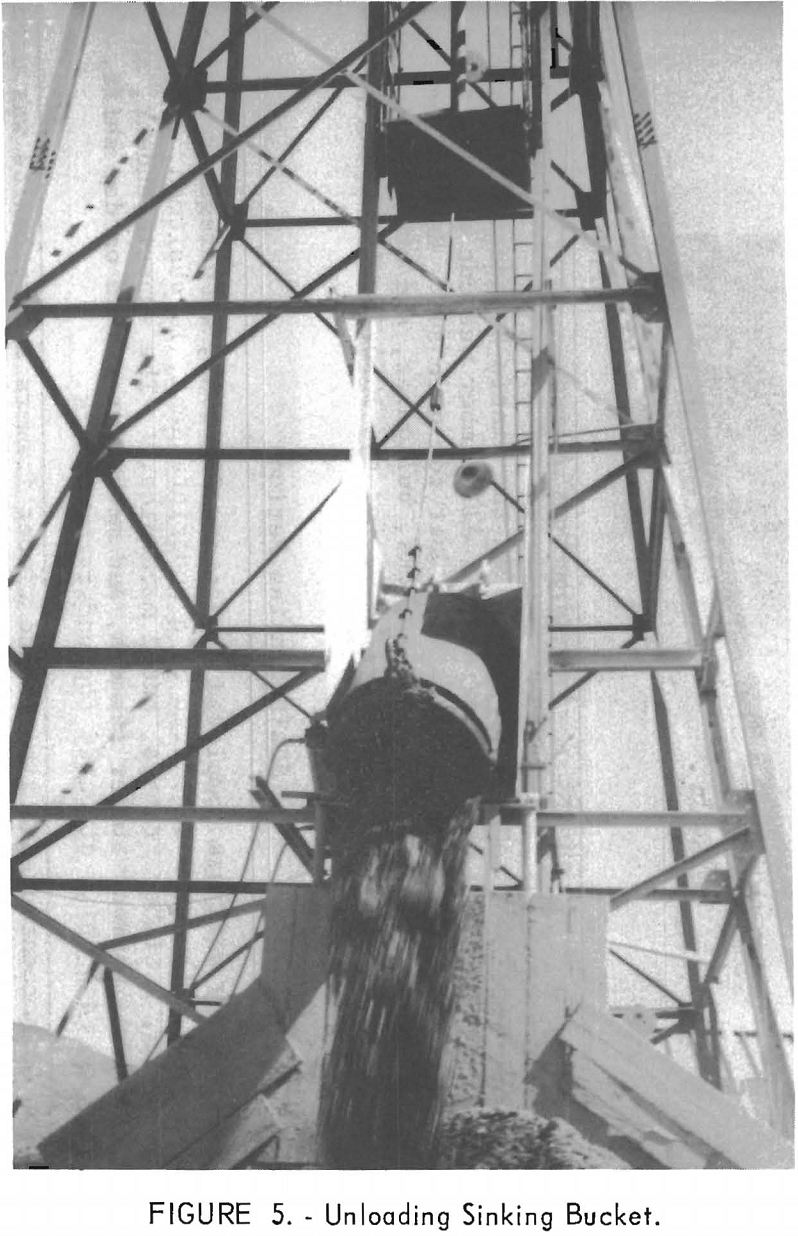
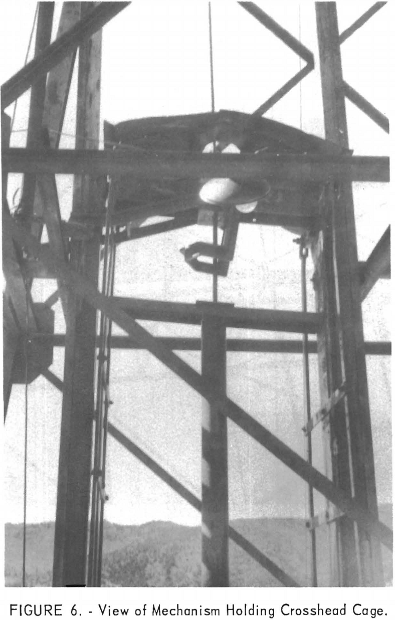
The headframe was equipped with a steel dumping apron, actuated by an air cylinder and operated by the hoistman (fig. 5). A stopblock that was attached to the headframe and activated by the dumping apron stopped the crosshead cage and permitted the bucket to be lowered on the dumping apron (fig. 6). In the dumping operation an iron ball, on the end of a 3-foot chain attached to the bottom of the sinking bucket, was caught in a slot in the apron; as the bucket was lowered, it turned over and the muck emptied on the ground. The empty bucket was raised and the apron swung to a vertical position, allowing the bucket and crosshead cage to be lowered into the shaft.
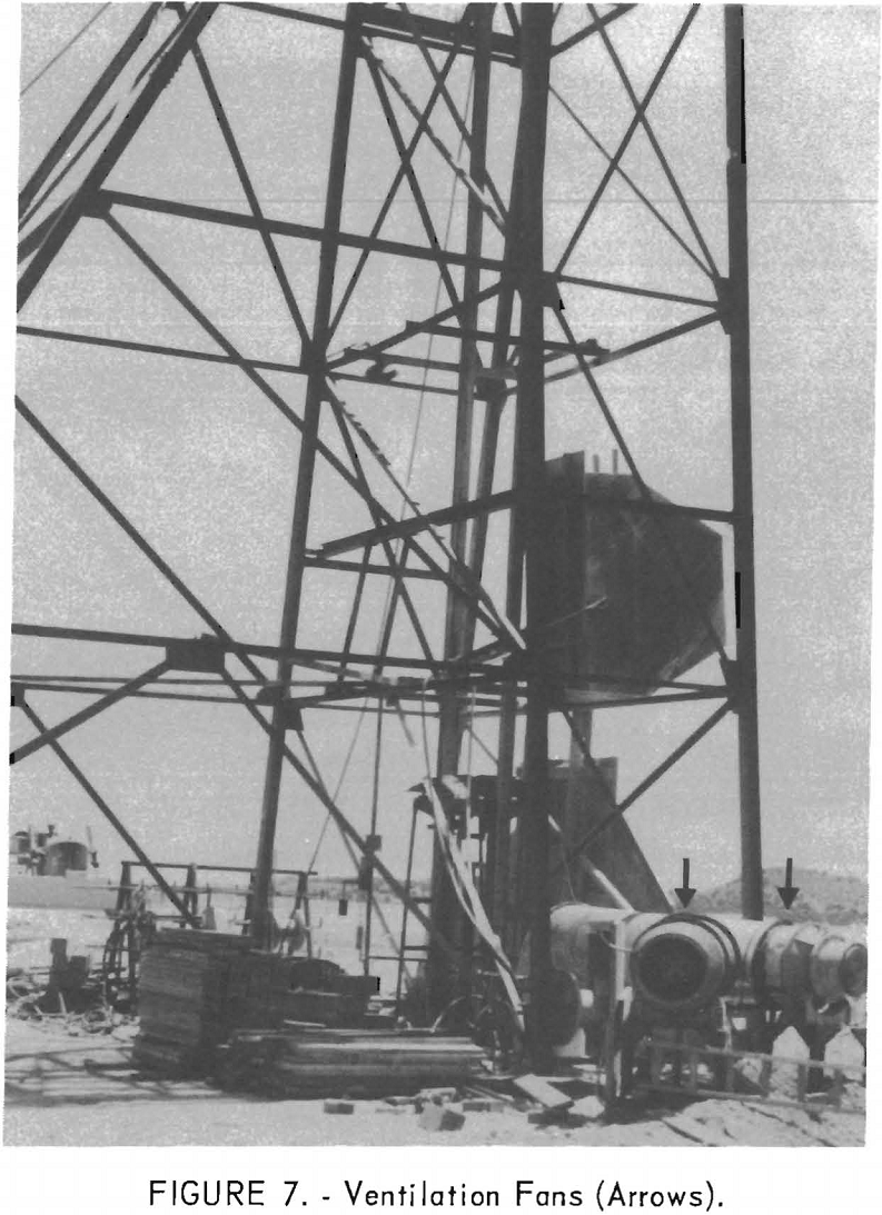
Ventilation is provided through 30-inch-diameter tubing constructed of 18-gage galvanized iron. Flanges on each end of the tubing, constructed of ¼- by 2-inch welded angle iron, are used to connect each section. A rubber gasket 1/8 inch thick separates all joints, which are connected by 12 3/8-inch- diameter machine bolts. On the surface the vent tubing branches into 2 segments, and in the end of each a fan is directly connected to a 15-hp., 440- volt motor (fig. 7).
The timber-framing and machine shops at the Tintic Standard No. 2 shaft surface plant were used by the contractor. All timber was cut and framed at this shop and delivered to the shaft as a unit for each set. Repairs on drills, steel, bits, mucking machine, trucks, bulldozer, and other equipment were made at the machine shop. Steel items for the 1050-level dumping pocket were also made in the machine shop.
Shaft-Sinking Period
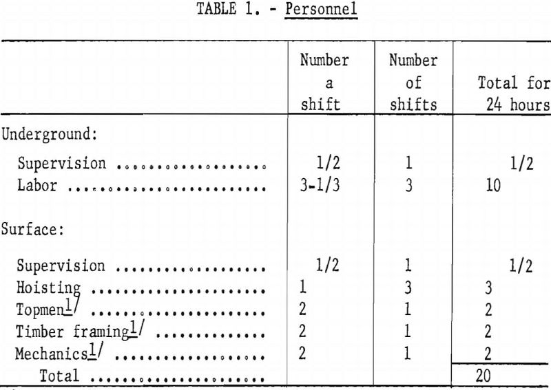
Preparatory work was completed by January 29, 1957, when regular shaft-sinking began. The crew consisted of a superintendent, 10 shaftmen, 3 hoistmen, 2 topmen, 2 timber framers, and 2 mechanics. The superintendent, an extra shaftman, topmen, timber framers, and mechanics worked on day shift. A leadman on each shift directed the underground work.
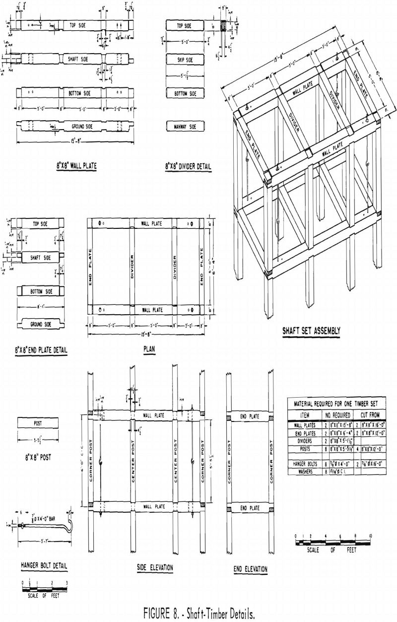
Outside timber measurements of the 2½-compartment shaft are 15 feet 8 inches by 6 feet 4 inches (fig. 8). Two compartments are 5 feet square, and the manway is 3 by 5 feet. Timber sets are 6 feet apart. Hanging rods are of 7/8-inch round steel 3 feet 7 inches long, threaded on one end and bent with a 3-inch hook on the other end. Two hanging rods hooked together supported one end of an endplate. Four hanging-rod supports were used for each set.
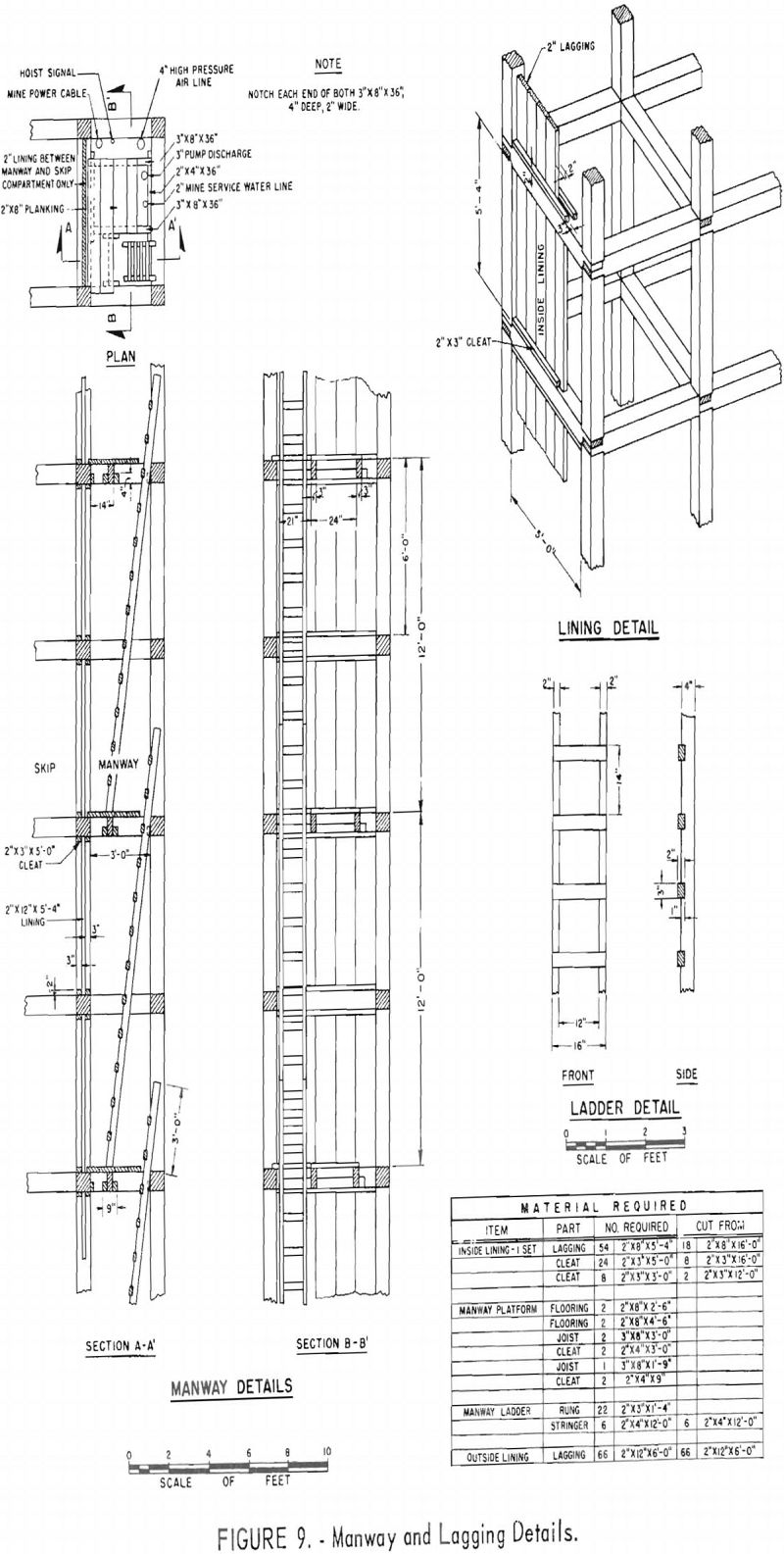
Hoisting was done in the center compartment. The manway compartment contained a 4-inch aluminum high-pressure air line, a 3-inch discharge waterline, and a 2-inch water-supply line, all ends prepared for victaulic couplings. Manway platforms were laid every 12 feet; and ladders were placed between platforms (fig. 9). Electric cable wrapped on a spool was strung down the shaft for a 120-volt light. A permanent line was strung for 800 feet, where the second spool was installed. The working area was illuminated by a 150-watt globe.
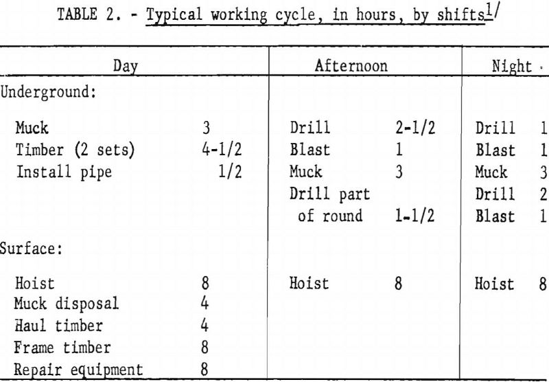
Average work cycle of the sinking operation was as follows:
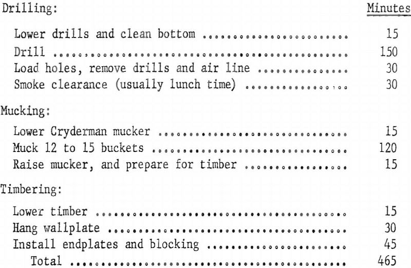
The timber panels were usually lagged while mucking was in progress. Generally two sets were installed every other day shift.
Drilling
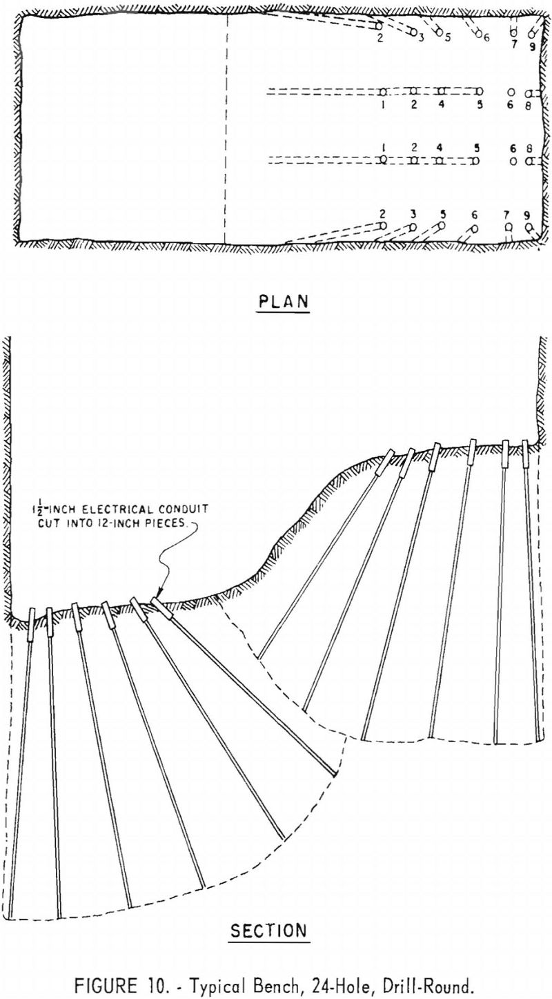
A sump or bench-type round of 20 to 26 holes was drilled to break half of the shaft bottom (fig. 10). Thus, one side of the bottom was always lower than the other and permitted drilling from a relatively clean, water-free surface. The side to be drilled was prepared by washing loose muck from the high side; compressed air also was used to clean the surface before drilling. One man attended to the drill steel, bits, and air hose; 2 men used 2 machines to drill the round. A round in rhyolite or dolomite consisted of 6 rows of 4 holes, each about 8 feet deep.
Drilling was done with handheld sinker drills weighing 56 pounds. The drilling rate in rhyolite and dolomite averaged about 1.4 feet per minute.
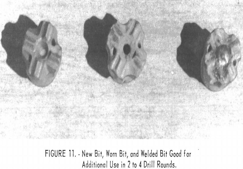
Hexagonal, 7/8-inch drill steel, in changes of 2, 4, 6, and 8 feet, was used, with throwaway tungsten carbide insert bits. Bit gage was 1½ inches for 2- and 4-foot steel, and 1 3/8 inches for 6- and 8-foot steel. Abrasive action of the ground caused excessive wear in the center of the bits and, after use for 3 or 4 rounds, the center of the bit was filled by welding (fig. 11). Usually 3 or 4 rounds were drilled after the welding before a bit was discarded.
A 5-gallon reservoir of drilling oil was installed on the air line to the shaft mucker, tugger, and sinker drills for lubrication. Drill water was obtained through the 2-inch waterline from the surface. Two pressure-reducing valves were installed on the waterline. A 1½-inch hose was used for the air line and ¾-inch hoses for the waterline to the sinker drills. Aluminum electrical conduit 1½ inches in diameter was cut in 1-foot segments and used to collar each drill hole. These collars were prepared by the mechanics and, wherever possible, were retrieved from the surface muck pile.
Blasting
Electric primers of standard 1 to 9 delays were used for detonation. A 40–percent ammonia gelatin dynamite in 1- by 12-inch cartridges was used with the primer, and a 45-percent dynamite with no noxious fumes, in 1- by 8-inch cartridges, was used as the general explosive. An average round for half of the shaft required about 80 pounds of explosive. Primers were wired in series, and the circuit was checked with a galvanometer before being connected to a 2-wire, 440-volt blasting circuit extending to the surface. A special blasting switch was used for the detonation.
Because the timber was 25 to 35 feet above the bottom of the shaft, no special provisions were required for protecting it in blasting. The lowest part of the mucking machine was always 35 to 45 feet away from the face being blasted. Rhyolite, limestone, and dolomite usually broke into small pieces, whereas the silicified limestone, dolomite, and quartzite broke into pieces as large as 10 inches on a side.
Fumes from the blasting were exhausted for about 20 minutes through a 30-inch ventilation pipe, and fresh air was blown into the bottom of the shaft during the remainder of the working cycle. Blasting was done any time during the shift but generally at the beginning of the lunch period or at the close of the shift. Because of the incentive pay system, deviations were made in the cycle to allow the maximum time underground.
Mucking
The shaft-sinking featured the use of the Cryderman shaft mucker (fig. 12). This machine was designed and first used in Canada. Several machines are now being used in the United States.
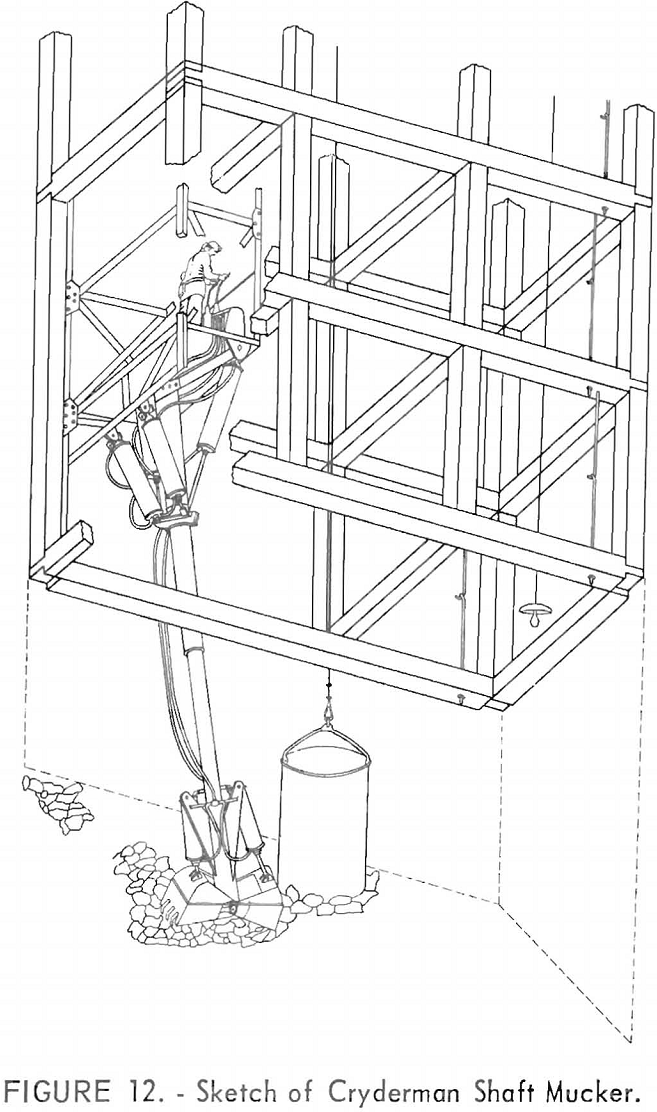
The shaft mucker occupied the manway compartment. In the lowering operation 1 man remained at the mucker controls, 1 man operated the air tugger hoist that lowered the machine, and a third man assisted in keeping the bull hose free of entanglements. The cage of the machine was secured to the wall- plates by chains before mucking started. Usually 10 to 15 minutes was required to lower the machines to mucking position. One man operated the mucker, and the other shaftmen installed lagging and dividers. Men were not allowed in the bottom of the shaft while mucking was in progress.
The sinking bucket measures 44 by 66 inches and has a volume of 53 cubic feet. About 2½ tons of broken rock can be loaded into the bucket, hoisted, dumped, and returned to the shaft bottom in 5 to 7 minutes. About 12 to 15 buckets were hoisted from an average round for half the shaft. The mucking and hoisting part of the cycle consumed about 2 hours.
The Cryderman shaft mucker features positive placing arid force closing of the clamshell. The machine consists of an angle-iron frame and the cage connected to a telescopic boom that has a 3/8-cubic yard clam bucket. The cage is made in 2 sections, each 10 feet long. A tugger hoist is anchored on the top of the upper section of the cage. The lower cage contains the operator platform and controls. The mucker was suspended from a 10-inch steel beam in the shaft by a 6-strand cable-pulley arrangement. The steel beam was chained securely between a divider and the endplate. The cage was made to fit the manway compartment by welding angle-iron skids on the front side, enabling the cage to slide up or down easily in the compartment. The telescopic boom is attached to the cage by a gimbal joint; an air cylinder within the boom activates its extension for 14 feet 8 inches, or to an overall length of 31 feet 8 inches. The retracted length is 17 feet. Two air cylinders, which are mounted at the front and on each side of the gimbal joint, control the swing of the boom from side to side. The maximum swing distance of the clam bucket is 14 feet to each side. Two air cylinders, at the back of the boom and connected to the cage, control the forward angular raising or lowering of the boom. The clam bucket is opened or closed by two air cylinders mounted on each side of the boom.
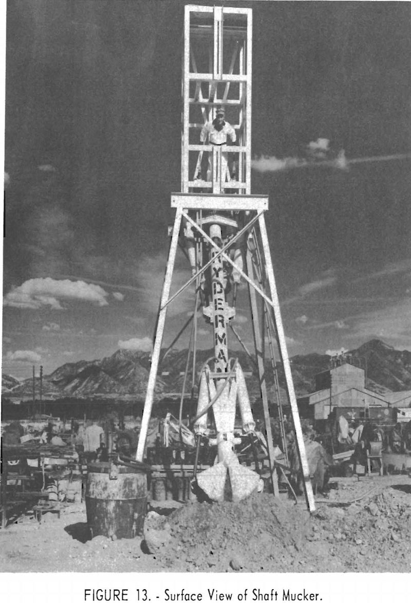
The operator stands on a platform at the bottom of the lower cage, where he can observe the bottom of the shaft, and the machine is controlled by two “joystick” levers connected to multiple directional valves (fig. 13). With the forward or backward movement of the lever at the right, the telescopic boom is extended or retracted. Sideward motion of this lever opens or closes the clam jaws. Forward or backward movement of the left lever controls the raising or lowering of the boom, and sideward movement controls the side motion.
The machine weighs 7,600 pounds, requires 500 cubic feet of compressed air a minute, and resembles a human arm, reaching forward and clutching a handful of muck. In sinking the Burgin shaft the machine was used to bail water into the sinking bucket. The operator frequently used the clam to pick up the bucket and place it in a more advantageous position in the shaft bottom. While a bucket was being hoisted, the muck from the far end of the shaft was transferred by the machine to the near side. Usually a small depression was maintained in the muckpile where the bucket was placed. The bottom of the shaft was cleaned by the machine, and no hand mucking was necessary. Operators for the machine were trained in 3 or 4 days.
At first shaftmen were prejudiced against use of the machine. During the first month of shaft sinking an operator dropped the boom, and repairs were necessary. Having to use the other methods of machine mucking convinced the shaftmen of the versatility and convenience of the Cryderman shaft mucker, and the men later regarded the machine highly efficient.
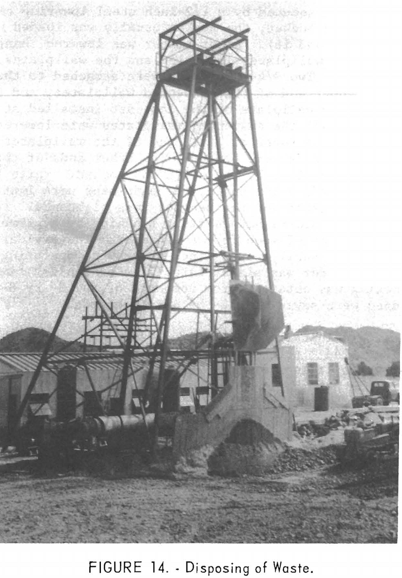
The hoisted muck was dumped to the ground. An average of 3 hours was required for a diesel bulldozer to move the muck accumulated by three shifts over the edge of the dump (fig. 14). Toward the end of the shaft-sinking phase of the work the volume of waste became so large that a front-end loader and a truck were used to transport the muck to the edge of the dump. These methods of handling surface waste proved satisfactory and economical and removed the need for a surface man at the shaft collar during the afternoon and graveyard shifts.
Timbering
Timber was framed according to specifications of the Bear Creek Mining Co. (fig. 8). All timber is No. 1 mining grade, rough, full-dimension, untreated Douglas fir; skip guides are spruce. Hanging rods are 7/8-inch round steel threaded on one end and hooked on the other. Bearing sets were placed every 150 feet and 2 sets below the 1050 station.
All shaft-support timber is 8 by 8 inches in cross section, except bearing timbers, which are 8 by 12 inches (fig. 4). The outside lining of the shaft is 2- by 12-inch by 6-foot planking, and the inside compartment lining is 2 by 8 inches by 5 feet 4 inches.
Two sets of timber usually were installed every other day shift, but occasionally 1 or 2 sets were installed on other shifts, according to need.
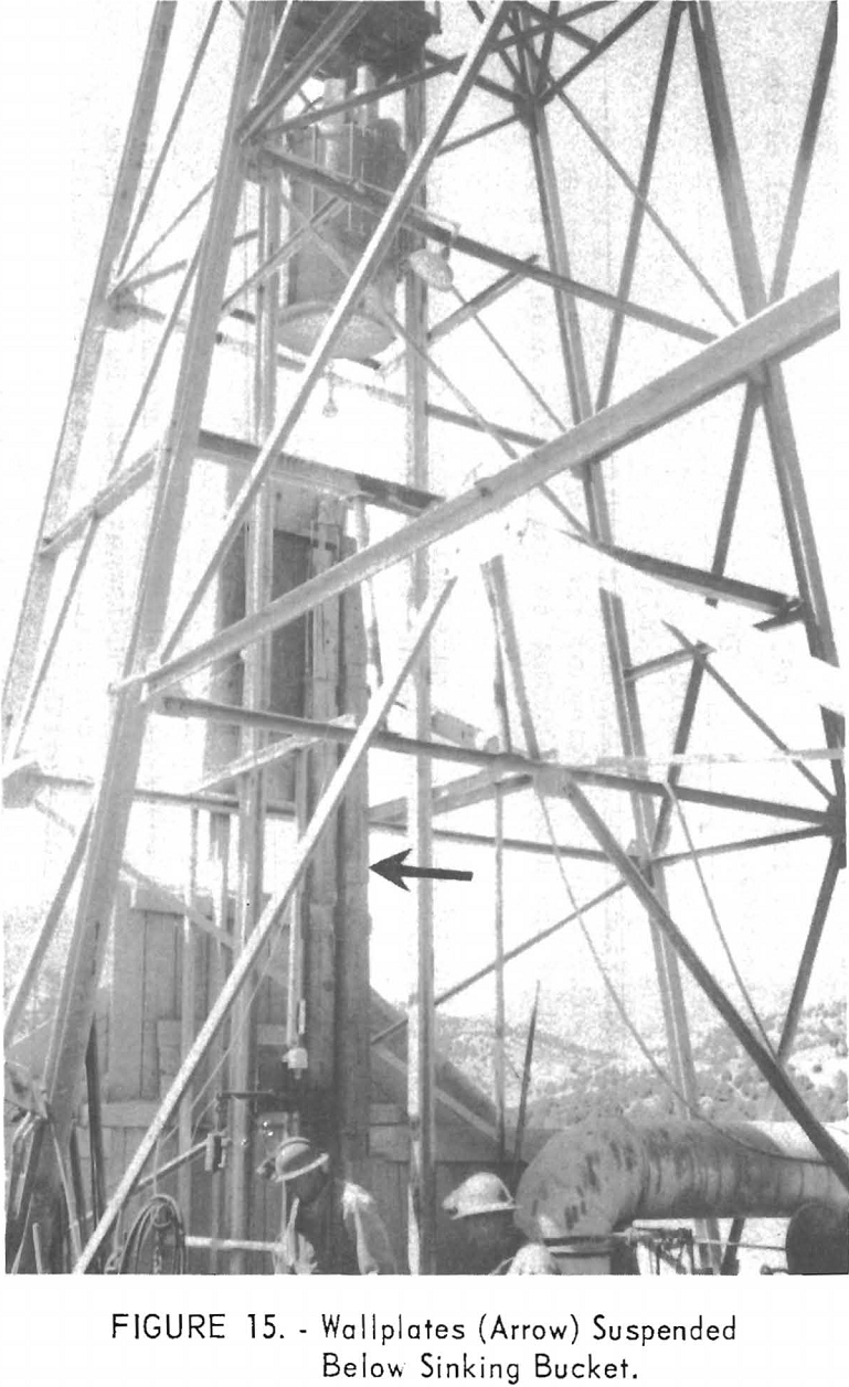
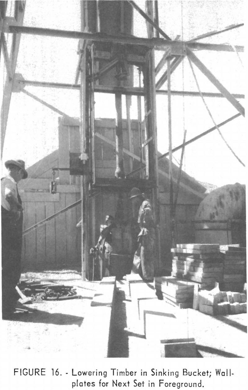
The longwall plates were secured by a ½-inch steel lowering clamp and suspended below the sinking bucket; the bucket usually was loaded with lagging and endplates (figs. 15 and 16). After timber was lowered, hanging rods were placed in both the last wallplates installed and the wallplates suspended below the sinking bucket, Two ¾-inch ropes were attached to the hook of the hanging rods on the lower end of the suspended wallplates, and the other end wrapped loosely over the wallplate of the last set installed at the hanging rod. At the proper signal the suspended wallplates were lowered by the hoistman. At the same time the ropes at lower end of the wallplates were pulled upward, and the hanging rods were hooked. The other ends of the hanging rods were merely lowered into place by the hoist and hooked. While the bucket was being hoisted to the surface for posts, the endplates were installed. The eight posts were soon placed and the hanging rods tightened. The set was alined in the opposite corners before final blocking by a plumb line the width of a ¾-inch piece of wood from the timber. The divider separating the manway compartment usually was omitted to provide operating space for the shaft mucker; this divider was placed later at a convenient time in the working cycle. Blocking was obtained from remnants of the 8- by 8-inch timber, and 12-inch wedges were sawed from 2- by 4-inch boards.
Timber sets were installed 8 to 30 feet from the bottom of the shaft. Usually 4 men installed 2 sets, not including lagging, in 4 hours. Lagging was placed by the available shaftmen, generally during mucking. Occasionally a complete shift was used to install lagging, dividers, manway platforms, ladders, and pipe. The shaft ultimately was timbered to the bottom; the last set has 12-foot posts for convenient removal if the shaft should be deepened.
Pumping
Water began seeping into the shaft bottom at a depth of about 180 feet, and at 200 feet bailing was begun. Occasionally the water became deep enough for direct bailing by the sinking bucket. Later a pneumatic sump pump was used to fill the bucket, which was then hoisted and emptied.
At a depth of approximately 300 feet a water-bearing zone was found that, after the first surge, yielded about 20 gallons of water a minute. A concrete sump was constructed around the outside of a set of timber to facilitate collecting the water. This ring dam is about 1 foot deep and 1½ feet wide. A low-volume, high-pressure, horizontal triplex pump was used to pump the water to the surface through a 2-inch line. The ring dam proved to be successful, but some water seeped into the shaft, making it necessary for the shaftmen to wear water-repellent suits over their clothing.
1050-Level Station
An excavation for station and loading pockets was cut from the south side of the shaft at 1,050 feet, and as the shaft was being sunk 3 headings were started to the west, south, and east. An air tugger-scraper was used for mucking the drift headings that extended only 15 feet from the shaft.
Wedge-type roof bolts first were used in the back of the station excavation. Steel plates used with the bolts are ¼ inch in thickness and 8 by 8 inches in cross section. The roof-bolt holes were drilled with a stoper drill. Later considerable scaling occurred, and the station was timbered and lagged.
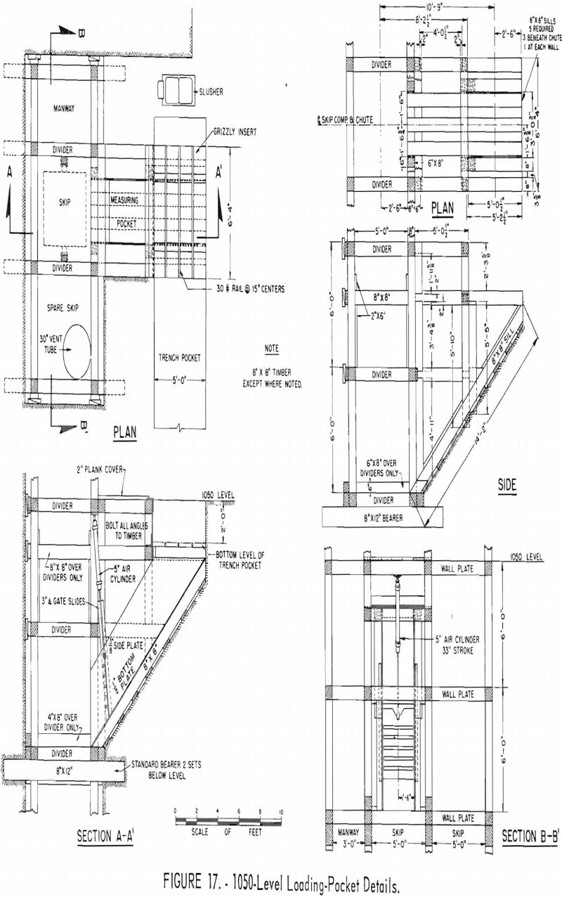
The measuring pocket is a timber-supported, metal-lined chute with sliding gates activated by an air cylinder. A trench 2 feet deep at the chute mouth was excavated as a pocket for dumping mined material. Thirty-pound rail on 15-inch centers was installed on the bottom of the trench for slusher loading into the chute (fig. 17).
A buzzer light signal system was installed, and a 20-pound mine track with station switches completed the shaft-sinking phase of the work.
Supervision and Labor
The job was supervised closely by a superintendent who worked regularly on day shift and was available on other shifts as needed. Each shift was directed by a working leadman.
Shaftmen were able to do all jobs necessary in the sinking operation. Centennial Development Co. has been successful in keeping well-coordinated crews together on this and other jobs. All men are paid on an incentive bonus system, with a guaranteed daily wage. At the Burgin shaft shaftmen were guaranteed a wage of $18.75 and leadmen, $19.75 a day. Actual wages, based on footage progress, exceeded the guaranteed wages, and time not spent in shaft-sinking work was not applied against the bonus. Hoistmen received $18.75 a day plus one-third of a shaftman’s bonus. The wages of topmen, timber framers, and repairmen ranged from $17.14 to $19.75 a day.
The company had no labor troubles. All men are members of a local of the United Steelworkers of America.
Safety
State safety regulations were observed. In addition, men were not permitted to work above others in the bottom of the shaft, and the hoistman indicated the approach of the sinking bucket to the working area by a blinking light.
The men are experienced miners, and many had taken previous safety training. Two lost-time accidents occurred during the shaft-sinking operation. The operator of the shaft mucker lost 1 day because of fractured ribs when the mucking machine was dropped 15 feet the first day it was put in operation; a second man missed 2 weeks of work because the drill fell on his foot.
Costs and Performance Data
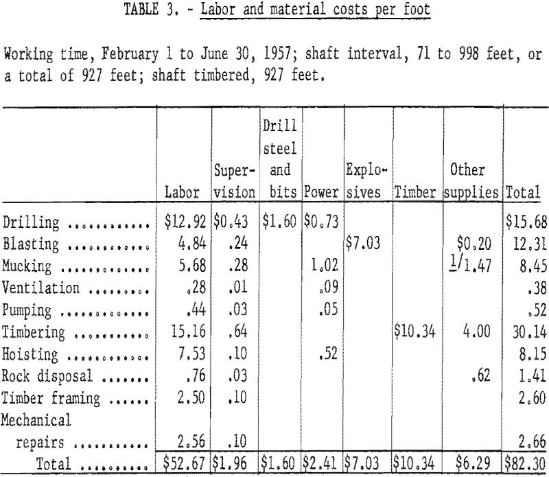
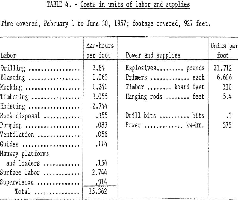
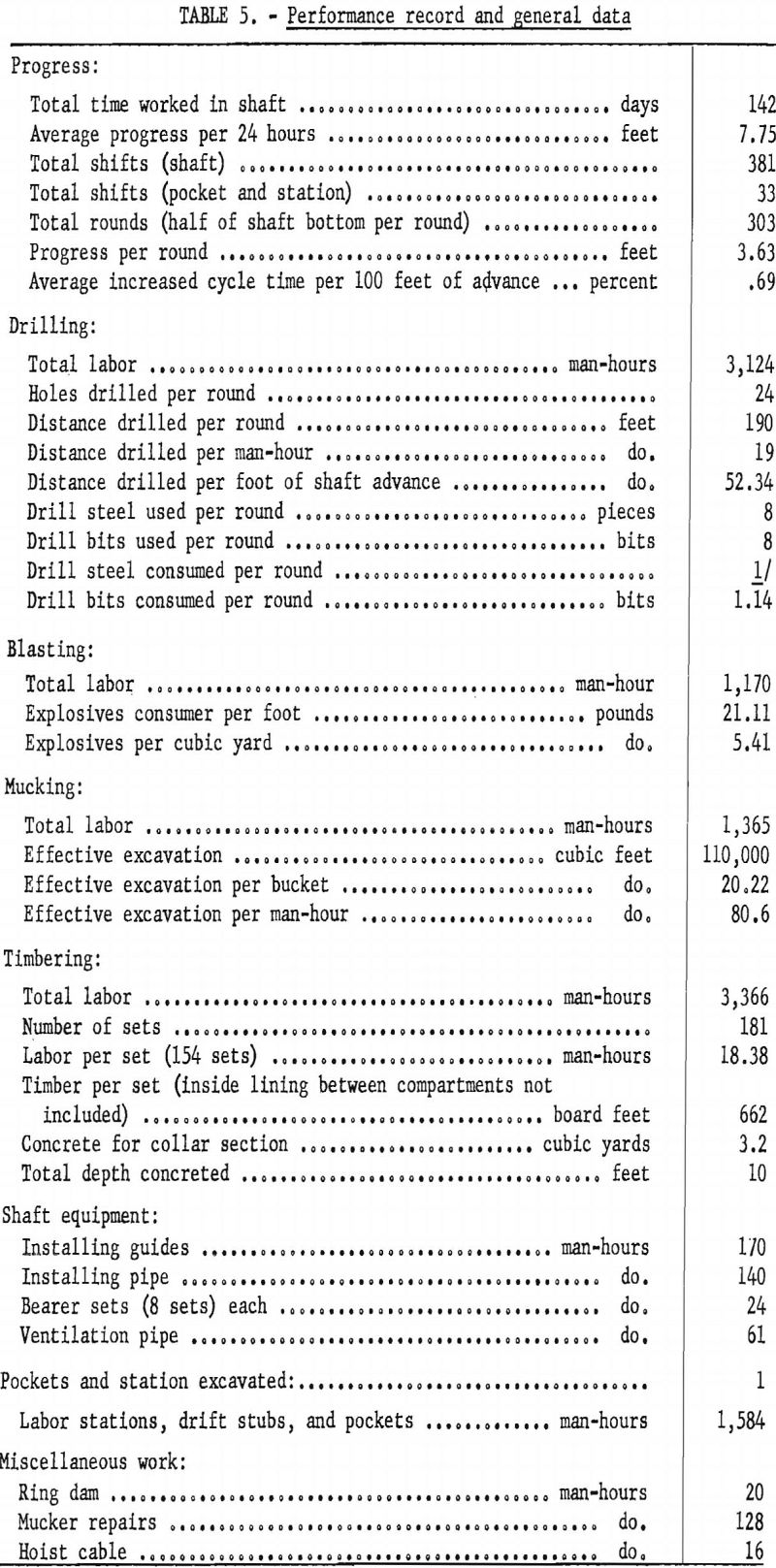
Costs and performance data are presented for the basic phases of the shaft-sinking operation. Data covering administration, accounting, amortization, taxes, insurance, preliminary work, equipment costs, equipment depreciation, equipment maintenance, pipe, concrete, tools, headframe, mechanical supplies, and other items are not available.
Cost and performance data are presented in tables 1 through 5.
Shaft Sinking EQUIPMENT
This report describes the sinking of No. 3 shaft at the Westvaco mine. It is one of a series of publications of the Bureau of Mines on mining methods and practices in the United States.
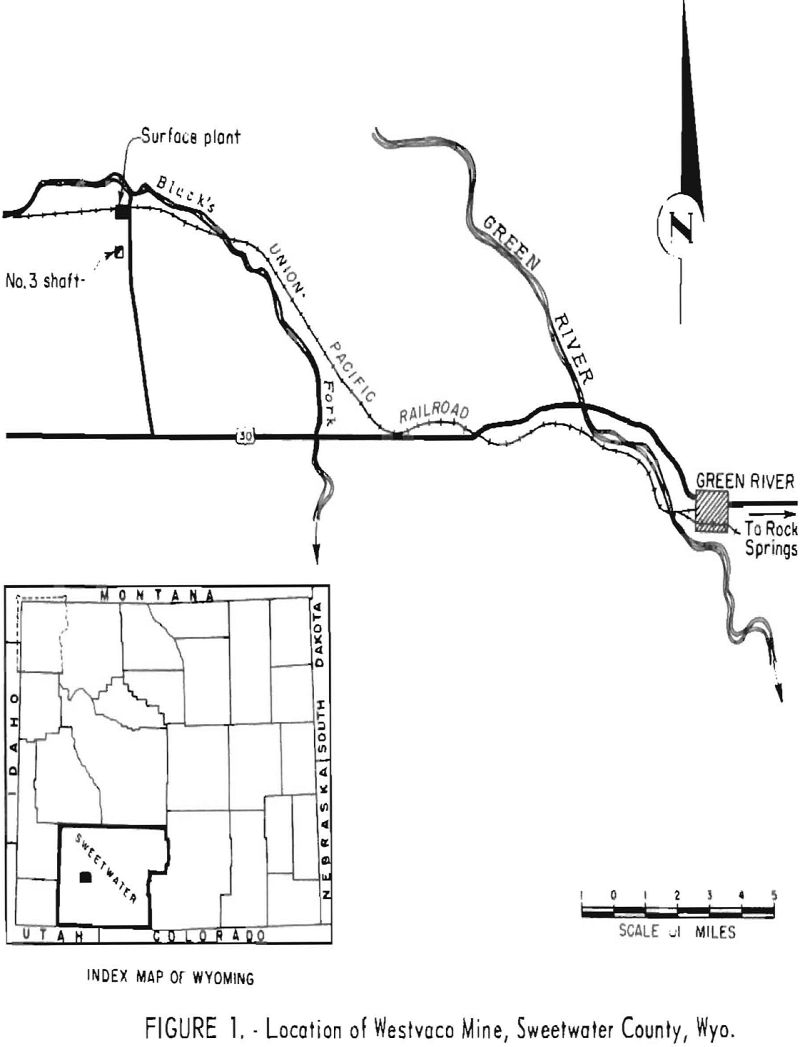
The Westvaco mine is in Sweetwater County, Wyo., approximately 23 miles northwest of the town of Green River (fig. 1). There are no permanent habitations in the vicinity of the mine, and employees live in Green River or Rock Springs, Wyo., 14 miles east of Green River. The mine plant is on a windswept, treeless plain, from which low buttes and flat-topped ridges rise. The altitude at the collar of No. 3 shaft is 6,351 feet. The climate is arid, with temperatures as low as 40° below zero in the winter. Blacks Fork, a tributary of the Green River and a perennial stream, flows near the mine.
The mine is reached over a hard-surfaced county road that extends northerly from U. S. Highway No. 30; a spur track of the Union Pacific Railroad provides shipping facilities for the mine.
The Westvaco mine product is trona (sodium sesquicarbonate), which has the chemical formula Na3H(CO3)2·2H2O. The deposit is unique because of its kind and great lateral extent. It is mined by a room-and-pillar method.
This report gives a brief history of the mine. It describes the trona deposit, formations penetrated by the No. 3 shaft, and methods of breaking and loading the rock and placing concrete shaft lining while sinking it. It also contains a brief description of mining methods used at Westvaco.
The Intermountain Chemical Co., operator of the Westvaco mine, contracted sinking the shaft to the Dravo Corp., Pittsburgh, Pa.
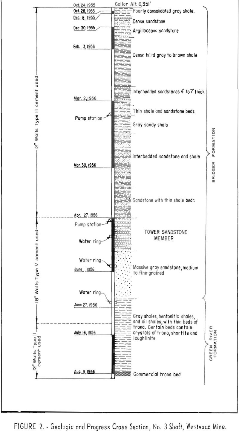
The shaft has a circular cross section, with an inside diameter of 18 feet. It is lined with concrete throughout its entire depth of 1,584 feet, which includes a 12-foot sump. The minimum thickness of the shaft lining is 12 inches where dry formations were penetrated and 18 inches where water¬bearing formations were encountered.
History
In 1896 alkaline water was encountered at a depth of 125 feet in a prospect well drilled near the town of Green River by the Green River Fuel and Oil Co. A sample of the water, analyzed at the University of Wyoming, proved to be a nearly saturated solution of sodium carbonate of greater purity than any found elsewhere in the State.
When other wells were drilled in the vicinity, alkaline water was encountered at approximately the same depth. A plant was built near Green River to recover the sodium carbonate in the brines from the shallow wells, but the operation was discontinued after World War I.
Trona was discovered west of Green River in 1938 when a fuel company was prospecting for oil and gas. Data obtained from subsequent drilling indicated a large reserve of trona at depths of 1,300 to 1,600 feet. In 1940 the Intermountain Chemical Co. drilled three core holes to confirm findings in holes previously drilled, and the company then made plans for mining the deposit.
No. 1 shaft, a concrete-lined, circular shaft with a 12-foot inside diameter, was sunk in 1946. The shaft encountered the commercial bed of trona approximately 1,500 feet below the collar. A period of development ensued between 1947 and 1953 while conditions that would affect mining the deposit were determined. Within the same period a pilot plant was constructed and research conducted to develop a refining process. No. 2 shaft, approximately 1,100 feet from No. 1 shaft, was completed in 1953. No. 2 shaft is concrete-lined and circular in cross section, with an inside diameter of 14 feet. No. 1 shaft is the service shaft for men and materials, and No. 2 shaft is used for hoisting the trona.
A multimillion-dollar surface plant was put into operation in 1953. Mine development produced all the trona that was processed until early in 1954, when systematic trona mining was begun.
Sinking No. 3 shaft was begun late in October 1955 – one shift daily until January 4, 1956, and two shifts daily from January 4 to February 13. After February 13 three shifts daily were utilized until the shaft was completed. Early in August 1956 the shaft was connected to a heading that had been driven in the main trona bed.
Geology
The trona deposit occupies the part of ancient Lake Gosiute that covered a portion of southwestern Wyoming and extended into Utah and Colorado. During the Eocene epoch the lake covered an area of approximately 30,000 square miles at its greatest extent. It was near sea level, and fossils indicate that it abounded with plant and animal life.
The trona deposit is intimately associated with oil shales, clay shales, and bentonitic shales of the Green River formation. The commercial bed ranges from 7 to 11 feet in thickness and lies about 1,600 feet beneath the surface. There are thin, noncommercial beds above and below the main deposit – a massive, opaque to translucent, finely crystalline ore ranging from white to brown.
Trona has the formula Na3H(CO3)2·2H2O. The mineral crystallizes in the monocllnic system, with a tabular habit. Its fracture is uneven to subconchoidal; its hardness ranges from 2.5 to 3; and its specific gravity from 2.11 to 2.14. Fibrous trona has a vitreous luster; massive trona is dull.
Other saline minerals associated with the Green River deposits are shortite, bradleyite, loughlinite, pirssonite, gaylussite, bromlite, searlsite, and northupite.
The trona bed dips slightly to the northeast. It is about 5 feet higher at the No. 2 shaft than at the No. 1 and approximately 40 feet higher at No. 3 shaft than at the No. 2.
The upper part of No. 3 shaft is in the Bridger formation (Tertiary) (fig. 2). This formation is composed of a series of gray to brown shales and sandstones. The Tower sandstone is the basal member of the Bridger formation. The lower 220 feet of the Tower sandstone is massive, gray, and medium- to fine-grained. The last 340 feet of the shaft was sunk through gray shales, oil shales, and bentonitic shales of the Green River formation. The shales are laminated and have little inherent strength.
Mining Methods
After the deposit was discovered and its extent recognized, plans were made for bringing the raw material to the surface,. Several unsuccessful attempts were made to recover the trona as a brine from deep wells. The No. 1 shaft was sunk in 1946, and preliminary work indicated that trona could be mined by methods employed in many coal- or salt-mining operations.
The mining method being followed was planned for a ventilation system with seven entries in the main development and four in the secondary development, which connected with two entries serving as return-air bleeders. Methane is released when sediments overlying the deposit cave; therefore the use of
permissible equipment and other precautions necessary in gaseous mines are required. Rooms, 20 feet wide and about 300 feet long, are driven on 65-foot centers at right angles to the secondary development. Pillars are extracted on the retreat by a system involving splitting pillars and leaving a protective fender between the caved area and the mining face.
The mine is completely trackless. It is equipped with 36-inch belt conveyors for hauling ore and with modified coal-mining equipment in the working faces. Electrically driven jeeps with rubber-tired trailers are used to transport men and materials through the mine. A trolley system permits the use of shuttle cars for hauling heavy materials and production equipment.
Undercutting
When preparing to break a face, a horizontal cut first is taken out at the bottom. Standard practice calls for a cut 6 feet wide and 10 feet deep in 20-foot rooms; in all other openings a cut 4 feet wide is used. The undercutting machine is mounted on rubber tires, has a 10-foot cutter bar, and operates at 220 volts a.c. The cutter chain has double bit blocks, with 117 tungsten carbide insert bits on each chain. Spray nozzles allay dust from undercutting.
Drilling
Two rock drills on hydraulically operated booms, mounted on a carriage with rubber-tired wheels, are used for drilling. Despite the hardness of the trona, drilling speeds exceed 10 feet per minute (f.p.m.). The number of holes in a round varies from 18 to 33, according to the width of the face. Holes 1-5/8 inches in diameter and 10 feet deep are drilled with tungsten carbide insert bits.
Blasting
Cushion shooting is employed; 1- by 16-inch cartridges are used in 1-5/8- inch holes. Low-velocity (approximately 7,600-f.p.s.) ammonia dynamite of 35- to 40-percent strength is used. Narrow work is shot with delay blasting in 6 intervals; wide work is shot with caps in 11 intervals. The caps are fired by condenser-discharge blasting machines.
Mucking
Conventional coal-loading machines, modified to cope with the heavier and more abrasive trona, are used to load the ore. In a fresh muckpile the machines have a trona-loading capacity exceeding 8 tons per minute.
Shuttle-Car Transportation
Ore is transferred from working areas in shuttle cars equipped with cable reels. The average payload of these cars is 8.5 tons of trona. The haulage distance between a working place and a belt-haulage transfer point generally is kept at less than 600 feet for efficiency. Normally, two shuttle cars are assigned to each working unit; however, conditions often require the use of three cars for best efficiency. Power is supplied to the shuttle car through the cable for normal shuttle service and through an overhead trolley for general area coverage.
Conveyor Transportation
A 36-inch-belt gathering system is used underground. The main haulage belt is 6,500 feet long; individual serpents are 3,145 and 2,950 feet long. Secondary conveyors extending into mining blocks are 2,600 feet long but are extended or retracted consistent with advance or retreat mining.
Shuttle cars discharge their loads onto the. secondary belt system through side dumping stations that can be moved and positioned readily. Transfer points have grizzly-slide sections that allow the finer material to form a protective layer on the belt. Impact idlers are used at all dumping stations and transfer points. Six-ply belting is used on the primary conveyor and five ply on secondaries.
The system is designed to convey more than 350 tons an hour of material ranging in size from large lumps to fines. The main conveyor discharges into a 21- by 60-inch, single-roll, toothed crusher. A 36-inch belt receives the ore, crushed to minus-3-inch, and conveys it to the shaft ore pocket, which has a capacity of about 800 tons. The ore is fed from the pocket over an apron feeder timed to fill automatically weighed hoppers, which hold the exact quantity to be loaded in the skips. The hoppers discharge the ore into the hoisting skips. This equipment is entirely automatic but can be controlled manually.
Transportation of Men and Materials
At first, underground employees walked from the shaft to their working places, but as the distances to the working areas increased it became necessary to provide a means of transportation. Several plans were considered but were discarded for various reasons. Rubber-tired haulage was selected. Jeeps were converted to electrically powered machines and operated off the trolley. The jeeps have 10-hp., d.c. motors installed under the hoods. They travel at speeds up to 10 m.p.h. and have adequate power to pull required loads.
Rubber-tired trailers are used in conjunction with the jeeps. Two-wheeled man trailers haul crews of 16 men, and small, four-wheeled trailers transport supplies. The supply trailers are purposely built short so they will fit Into the man cage at No. I shaft. Thus trailers can be loaded on the surface, lowered through the shaft, and taken to a working place. A jeep sometimes hauls three or four trailers. Roof bolts and powder are the principal supplies used underground and are readily hauled in the trailers.
Construction and maintenance of roads create problems. If supplies are to be transported rapidly, roads must be kept in good condition. The road surfaces are oiled and maintained with a diesel-driven bulldozer. Continual travel and maintenance have improved the main roads so that they resemble a macadamized road. The use of diesel-driven equipment underground has been limited to the one bulldozer employed to maintain the roadbeds. The engine has an approved scrubber on its exhaust.
In addition to the jeeps and trailers, small three-wheeled battery-powered scooters art used by foremen, engineers, and maintenance men.
Roof Bolting
Trona occurs in a nearly horizontal bed averaging about 10 feet in thickness. Horizontal sediments, shales, and sandstones lie above the deposit. Approximately 400 feet of gray shales, with little inherent strength, lies immediately above the trona. The trona is underlain by a bed of oil shale, which is susceptible to heaving as rock pressures adjust for openings.
Conventional ground-support techniques were used in the early stages of development, but it soon became apparent that another method of support was necessary for safety and economy. Roof bolting was adopted as standard roof- support technique after such factors as sag, nut-torque, bolt length, anchor point, and pull-tests were studied under close engineering control. A split-rod and wedge-type bolt, 5 feet long, was adopted first as standard; however, recent work revealed that an expansion-type bolt gives results equal to those obtained with the split-rod type, and the expansion-type bolt is more economical to use. Spacing bolts on 4-foot centers is normal procedure at the West- vaco mine. Bolts have been used to hold ribs, hang equipment, and stabilize the footwall. A substantial section of the main conveyor belt is suspended by roof bolts.
Power
Electricity is generated at the surface plant by two 4,000-kw., steam-operated turbines. Natural gas is the fuel burned. A tie-in with the local power company provides for emergency power requirements.
Electricity is generated and distributed at 4,160 volts. Power is transmitted to the mine area by armored or shielded cables in each shaft. Transformers at working faces reduce the voltage to 220 volts. Cables feeding the transformers are extended as working places advance. Circuit breakers protect the power-transmission system in the working places. All equipment, except shuttle cars and jeeps, operates at 220 volts a.c. Motor-generator sets, driven by motors of higher voltage, provide 250-volt d.-c. power for shuttle cars and jeeps.
Services
Two well-equipped repair shops are situated underground where mine equipment is maintained. In rare instances, when the facilities of the shops are inadequate, equipment is hoisted to the surface for repair. Because of distances between working places and surface facilities, repair parts are stocked in underground storerooms. Shop and store areas are moved at proper intervals to keep within a reasonable distance of working faces.
Mine Production
The mine normally is worked 5 days a week, and activities are concentrated on the first and second shifts. Extra production or additional maintenance is done on the third shift as required. The refining plant is operated 7 days a week by drawing from ore stockpiled on the surfaces. Approximately 2 tons of crude ore is required to make 1 ton of soda ash.
Approximately 2,500 tons of trona ore is produced daily by five operating crews; the fifth crew is diverted from production to perform other mine services as needed.
A standard unit, or crew, is composed of 14 men under the direction of a shift boss or unit foreman. Production ranges from 400 to more than 700 tons a unit shift, depending on whether or not a crew Is working on development or extraction. The average output of a face crew is more than 40 tons a man-shift and the average output of all mine-production personnel more than 20 tons a man-shift. The entire mine staff, including supervisors, clerks, engineers, miners, and maintenance men, averages approximately 140 employees.
Ventilation
A properly planned ventilation system is mandatory because the adjacent shales contain methane, which might be released in substantial quantities if the roof caved or the floor heaved.
Before No. 3 shaft was sunk, the mine was ventilated by a 5-foot fan underground between Nos. 1 and 2 shafts. A volume of 120,000 c.f.m. of air was circulated at about 4 inches water-gage pressure.
After No. 3 shaft was completed, the volume of air circulating in the mine was increased to 300,000 c.f.m. at 8 inches water-gage pressure. Two parallel, 5-foot-diameter, axial-flow fans at the collar of No. 3 shaft supply ventilating air for the mine. These are pressure fans making No. 3 shaft downcast. A bleeder system of entries at the extremities of the mining area provides a unidirectional flow of ventilating air through the mine.
Sinking No. 3 Shaft
No. 3 shaft, approximately 1-¼ miles south of the surface plant, is on a low, gently sloping hill. It serves as the intake airway for the mine-ventilation system. Provisions have been made for converting it to a hoisting shaft when future mining requires the change. Guides were not installed during sinking, but bunton hitches were formed in the concrete lining to permit future installation of guides.
Surface Plant and Equipment
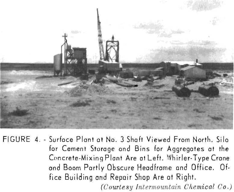
During sinking operations the surface plant and equipment consisted of a repair shop, hoist and hoisthouse, headframe, whirler-type crane, concrete-mixing plant, a carriage for transporting equipment to and from the collar of the shaft, and a building that contained the office, warehouse, changeroom, blower, and compressors.
Office, Warehouse, Etc.
The building used as an office and to shelter other facilities was designed to be an integral part of the mine-ventilation system. Air for circulation through the mine is drawn through louvers in the end of the building. In winter air passes through gas-fired heaters and is forced into the mine by two 5-foot blowers. The heaters are bypassed in the summer.
A blower, with a rated capacity of 5,000 c.f.m. at 1 pound of pressure, forced air into the shaft through an 18-inch ventilation pipe during sinking operations.
Compressors
Two electrically driven compressors of 550 and 850 c.f.m. rated capacity supplied compressed air for drilling, loading, and operating other air-driven equipment. A standby diesel-driven unit supplied compressed air when electric power failed. Compressed air was transmitted through a 4-inch pipe with victaulic couplings. A 2-inch pipeline was installed for transporting water or grout. All pipes in the shaft were suspended from expansion bolts set in shields placed in the concrete lining as it was poured.
Hoist and Headframe
A hoist with a single drum, 5 feet in diameter and having a 4-foot face, was housed in a temporary building. The 350-hp. motor on the hoist operated on 2,300 volts a.c. The hoist was equipped with two sets of hydraulic brakes. One set was controlled by the hoistman, and the other would operate automatically if the hoistman suddenly became incapacitated while the hoist was running. The 1-1/8-inch, nonrotating hoisting cable had a maximum rope speed of 735 f.p.m.
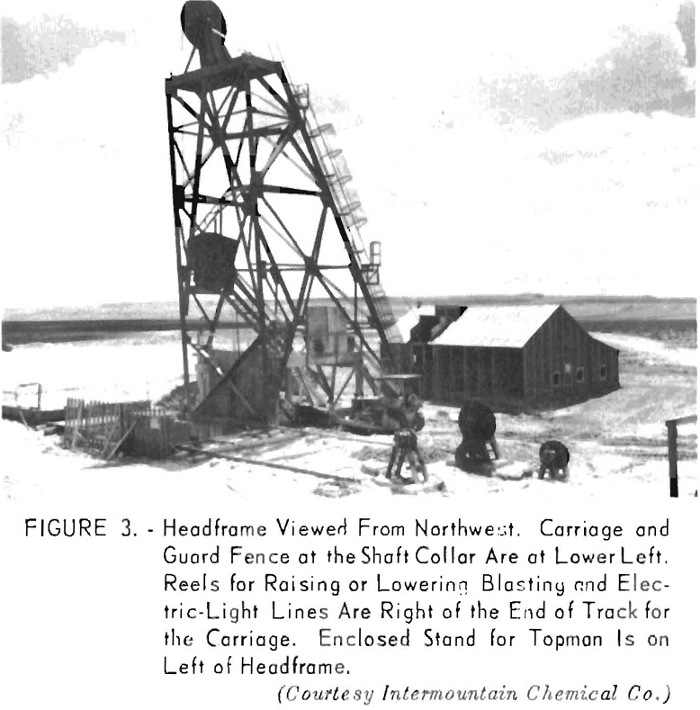
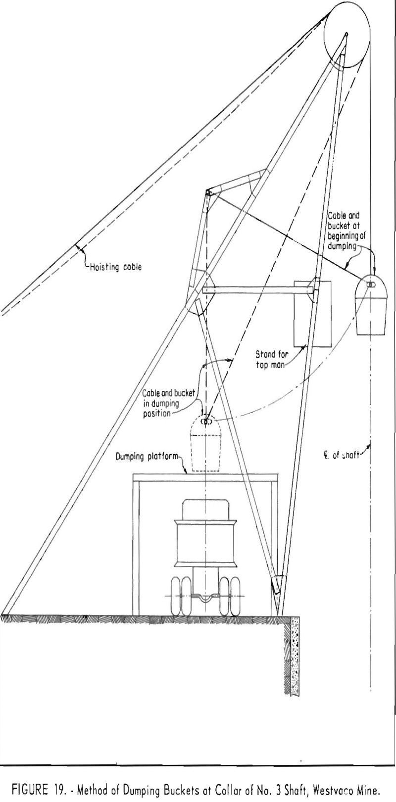
The steel headframe was 55 feet high and was surmounted by a sheave wheel 90 inches in diameter (fig. 3). Stairways on the headframe had steel-grid treads and were enclosed in wire mesh. An enclosed stand was built onto the headframe to provide a place for the topman to work when hooking the dumping cable into the bails of the buckets.
Crane
The whirler-type or full-rotating crane was fabricated by the Dravo Corp. (fig. 4). The crane had an 85-foot boom and was mounted on wheels that traveled on a short track made of 120-pound rails. This mounting stabilized the crane when equipment was loaded or unloaded. The crane was operated by a 150- hp. 440-volt, a.-c. motor. The crane was used to load and unload equipment and concrete forms onto a carriage for transportation to and from the collar of the shaft.
A clamshell bucket was used in conjunction with the crane to excavate the upper 120 feet of the shaft and to load aggregates from stockpiles into bins of the concrete-mixing plant.
Concrete-Mixing Plant
The concrete-mixing plant was a short distance from the collar of the shaft (fig. 4). The plant consisted of a concrete mixer with a capacity of 2 cubic yards per batch, bins for storing, scales for weighing aggregates, a screw conveyor, a bucket elevator, and a silo for handling and storing cement.
Carriage
A carriage mounted on wheels and propelled by an air-driven motor mounted on its deck transported equipment and concrete buckets to and from the shaft on a track that straddled the collar of the shaft (fig. 5). The carriage was 18 feet wide and 21 feet long and covered the shaft when in position for load¬ing or unloading at the shaft. It was constructed of channel iron with a
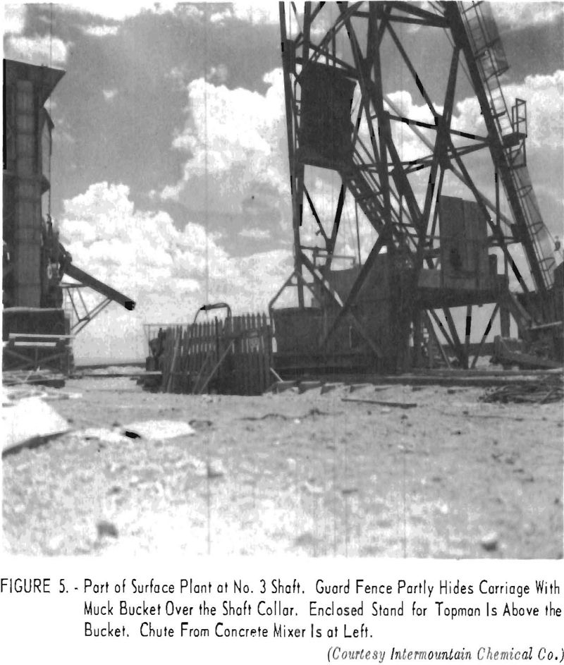
wooden deck. Guardrails and wire-mesh enclosures were used for the safety of the men standing on the deck during loading or unloading.
Equipment or concrete forma to be lowered into the shaft were placed on the carriage by the crane. The carriage was moved over the shaft, and the equipment or forms were picked up by the mine hoist. The carriage then was moved from the collar of the shaft, and the equipment lowered into the shaft. Equipment was removed from the shaft by reversing that process. The track on which the carriage traveled extended from the shaft to the concrete-mixing plant. When concrete was being placed, the carriage shuttled between the mixing plant and the shaft with loaded or empty buckets, which were lowered or raised through the shaft by the mine hoist.
Miscellaneous Surface Installations
Reels, operated by air-driven motors, were installed near the collar of the shaft on the side opposite the concrete-mixing plant (fig. 3). The reels held electric light and blasting lines that were raised or lowered as required.
A repair shop, equipped for welding and making repairs to equipment, was near the equipment storage yard. When not in use, the equipment and concrete forms were stored on the surface in places convenient for loading by the crane.
Power
Steam-turbine-turned generators installed at the surface plant of the Westvaco mine supplied electric power. Transformers near the shaft reduced the voltage from 4,160 to 440 for all equipment except the hoist motor, which operated at 2,300 volts. A portable generator capable of developing 250 kw, was installed for emergencies. A diesel-driven engine powered the generator. The standby unit had enough capacity to supply power for the crane, hoist, compressor, lights, or blower but could not meet demands if all units were operated simultaneously.
Drilling and Blasting
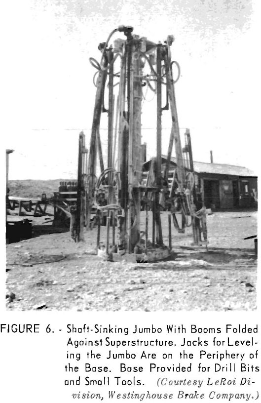
A shaft jumbo equipped with four rock drills mounted on jibs was used for drilling. The jumbo weighed 9,000 pounds, which was adequate to hold it in place during drilling. The base of the jumbo was circular, was 5 feet in diameter, and had six screwjacks for leveling it before drilling (fig. 6). Each drill and boom could be operated independently. All parts were moved by air motors; the controls were within easy reach of the operators. Compressed air for the drills and motors that operated the booms flowed through a 3-inch hose into the main column, which served as an air receiver. A ladder on the main column provided access to the superstructure. The jumbo had an overall diameter of 11 feet 6 inches when the jibs were folded against the main column (fig. 7). The drills, however, could be positioned so that the complete unit could pass through a 7- by 10-foot opening.
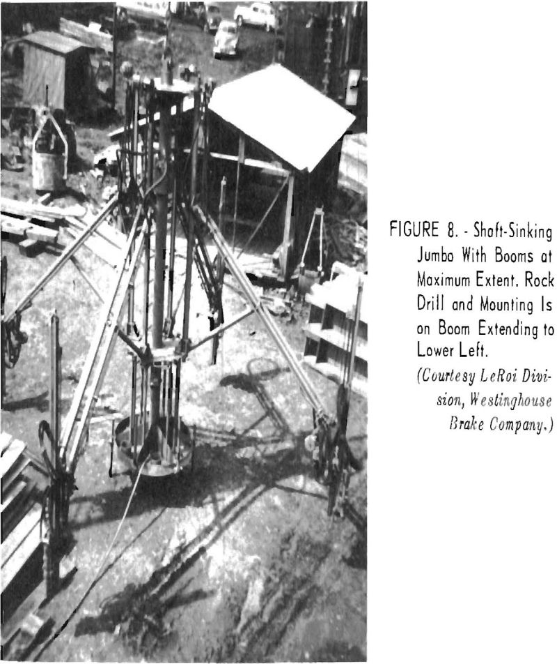
The booms could be extended 13 feet. Links sliding on columns of the superstructure permitted drill mountings to maintain the same distance above
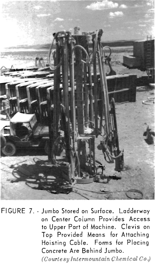
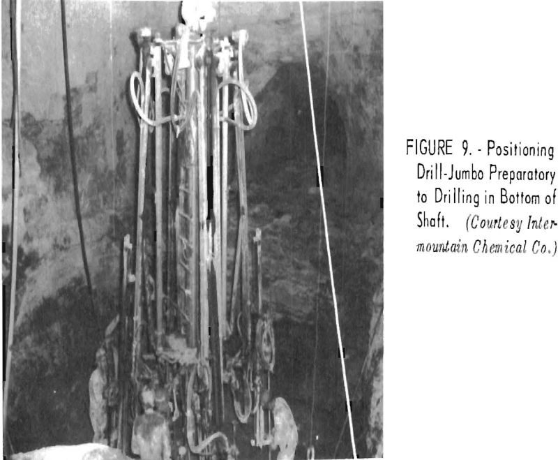
the base in all positions (fig. 8). Drill mountings were equipped with chain feeds having 6-foot runs. Sets of 6- and 12-foot lengths of 1-inch, hexagonal-type drill steel were used. Detachable, throwaway bits with 1-7/8-inch gage were used to drill the first 6 feet of hole, and 1-¾-inch-gage bits were used to complete the hole. Four test holes were drilled 5 feet deeper than other holes of the round to explore underlying formations for water and methane. The last 5 feet of the test holes was drilled with 1-5/8-inch bits. Figure 9 shows the jumbo after it had been lowered into the shaft. The base of the jumbo provided space for drill steel, bits, and small tools. The top of the jumbo was equipped with a clevis in which the hook on the hoisting cable was inserted when the jumbo was moved into or from the shaft.
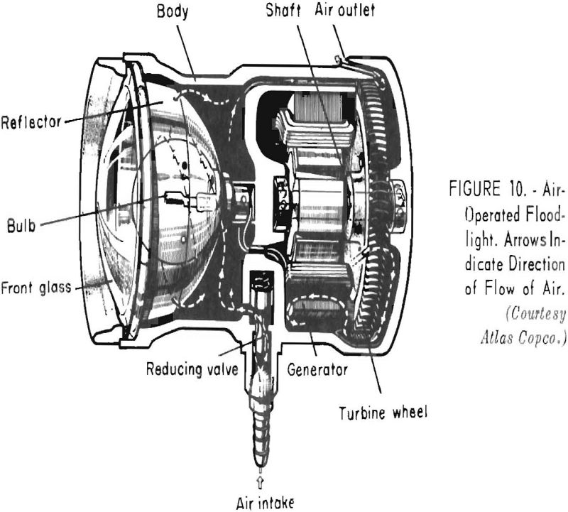
The bottom of the shaft was illuminated by four electric floodlights mounted on the jumbo. Two were connected to surface powerlines, and the other two received power from built-in, air driven turbogenerators (fig. 10).
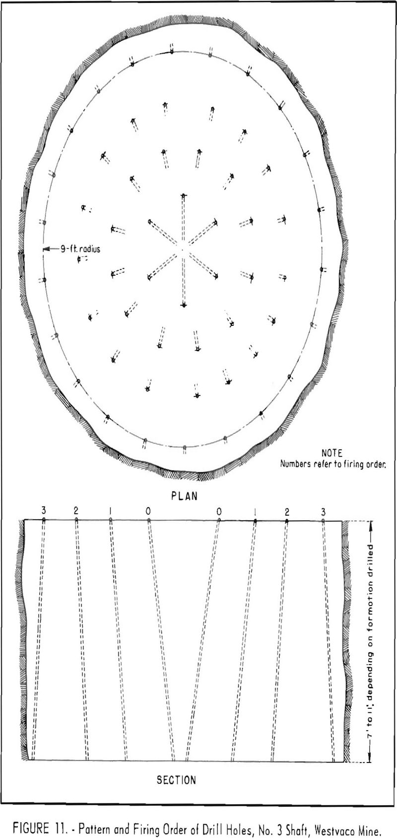
Shaft rounds averaged 57 holes in soft shales and 65 holes in harder sandstone. Holes were drilled 11 feet deep in shale and 7 feet in sandstone, which tended to heave when pressure in the rock was relieved. The drilling pattern was four rings of holes spaced approximately every 2-½ feet around the circumferences of the rings (fig. 11). Rounds were begun by drilling holes on the circumference of a circle with a 9-foot radius – the neatline of the concrete lining. These holes were inclined slightly toward the outside of the shaft. Holes on the next two inward rings were staggered to give optimum fragmentation and were inclined toward the center of the shaft. The fourth or innermost ring of six holes formed a pyramid-type cut. The holes were inclined to almost intersect at the center of the shaft.
Each round was charged with approximately 250 pounds of 40-percent dynamite. Special gelatin dynamite was used when water-bearing formations were blasted. Holes were, double primed to insure good fragmentation essential to mechanical loading. A detonator and half the charge were loaded and tamped in the hole; 2 feet of stemming was tamped on the powder; and another detonator and the remainder of the charge were loaded and tamped on the stemming. Charges in the cut holes were detonated by millisecond blasting caps, and the other rings of holes were fired progressively outward with standard-delay electric blasting caps with a delay of 1 second between each shot. Approximately 2 pounds of dynamite was required to break 1 cubic yard of shale and soft sandstone, and as much as 4 pounds to break the same amount of dense sandstone.
The drilling and blasting sequence usually required about 3 hours. The drilling of some rounds in sandstone was difficult and required more time because the bottom heaved when pressures in the rocks were relieved.
Loading
A crane with a clamshell bucket removed broken rock from the shaft during the early stages of sinking. The loadline of the clamshell was attached to the crane hoist, and the closingline was operated by an air-driven hoist mounted in the clamshell. After the mine hoist was installed and the headframe
completed, the clamshell dumped into buckets, which then were raised to the surface by the mine hoist. By manipulating taglines, two men maneuvered the clamshell into position for picking up the muck and dumping it into a bucket. A third man operated an air hoist, which opened and closed the jaws of the clamshell, by means of two lines attached to an air valve. A fourth man operated signal systems to instruct the craneman and mine hoistman when to hoist and lower.
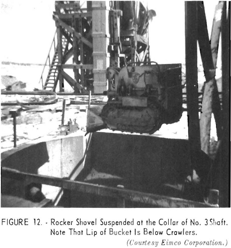
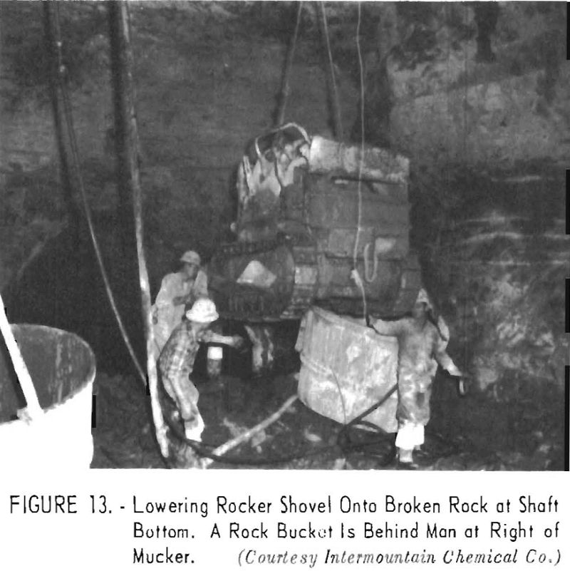
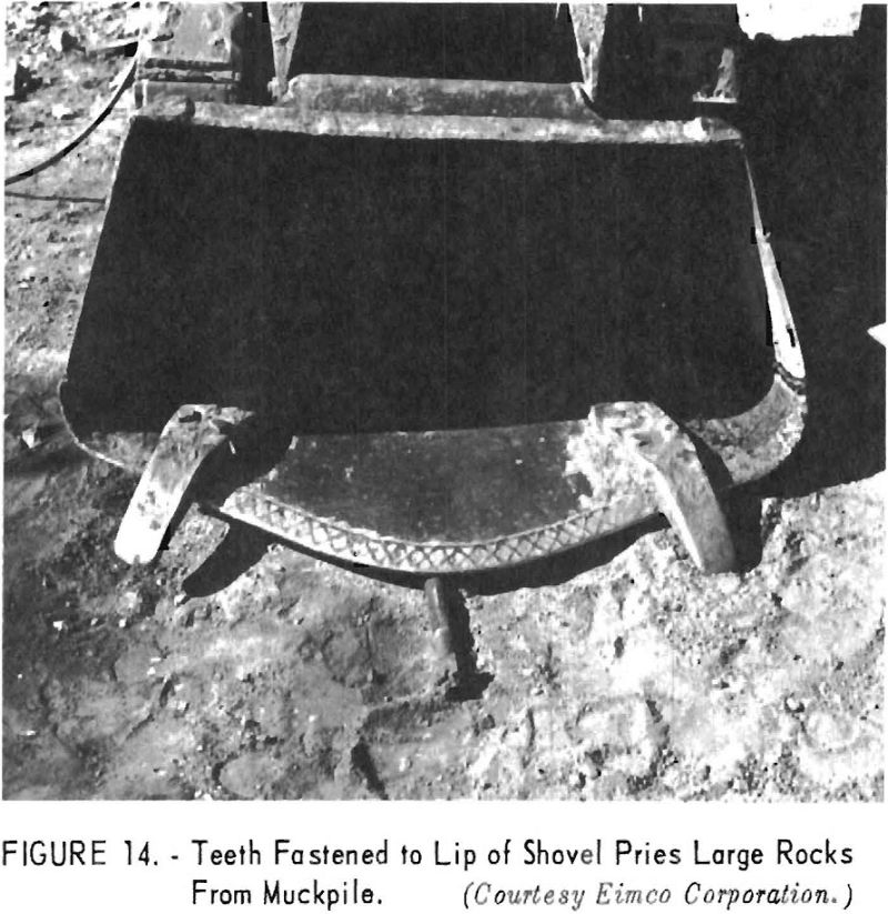
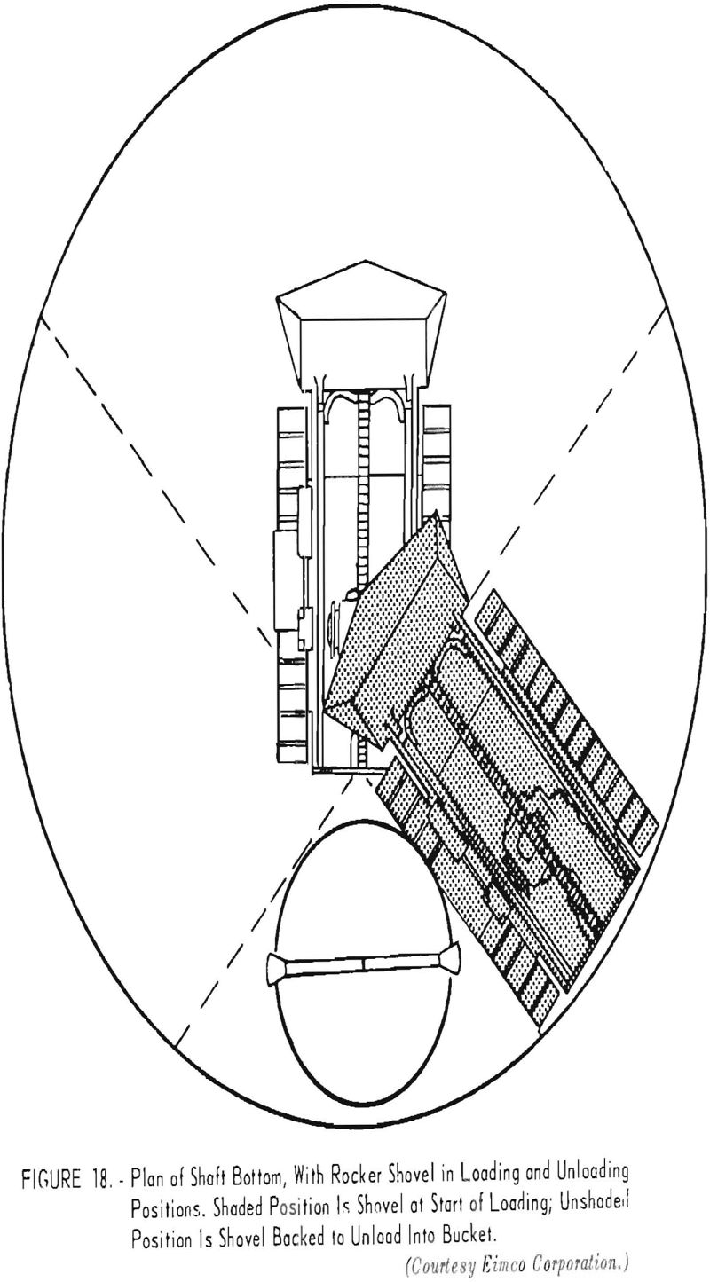
A rocker-shovel-type loader mounted on crawls was provided when the shaft reached a depth of 120 feet. The length of the loader was 9 feet 4 inches with the shovel down and 6 feet 3 inches with the shovel up. The width of the loader was 5 feet 9 inches. The loader weighed 5 tons, and Its shovel had a capacity of 9 cubic feet. The loader was built so that the bottom of the shovel in loading position was lower than the crawlers (fig. 12). Each side-plate of the loader had a hole in which clevises were inserted when transporting the machine through the shaft (figs. 12 and 13). Two teeth were bolted to the bottom of the shovel to pry larger rocks from the muckpile (fig. 14).
Three air-driven motors supplied power to the loader. One motor operated the hoisting chain on the shovel, and each of the other motors drove a crawler that propelled the machine; this arrangement gave excellent maneuverability. By running the crawlers in opposite directions the loader could be turned in its own length. The operator stood on a small platform on one side of the machine (fig. 15). Three levers to air valves that controlled the entire operation of the loader were within easy reach of the operator. Compressed air was supplied to the loader through a 2-inch hose, and during loading one member of the crew kept the hose away from the crawlers. Two other men guided empty muck buckets, capacity 2-½ cubic yards, into position for loading and
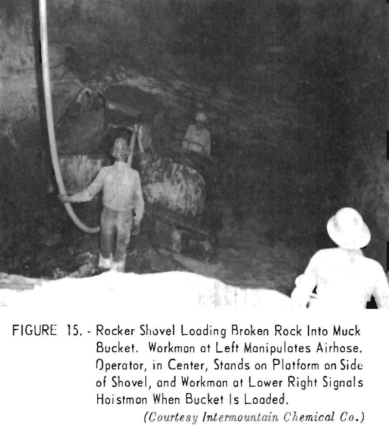
unhooked them. When the buckets were full, the men hooked them to the hoisting cable for transportation to the surface. A fifth man signaled the mine hoistman to move the bucket.
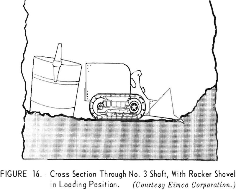
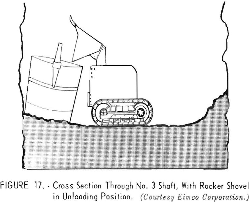
The loading cycle in the No. 3 shaft began by shaping the muckpile, which took 10 to 15 minutes. Experience showed that a saucer-shaped muckpile surface was best for loading while sinking No. 3 shaft. Working across the shaft, the loader kept the center of the pile lower than the edges (fig. 16). The loader was backed against the rib, and because the center of the muckpile was lower than the edges, the shovel sloped downward and began digging as soon as the machine started forward. It was relatively easy to keep the center of the pile low and fill the shovel quickly, because the loader moved forward until the dipper was full. The loader then was backed to a muck bucket placed along the rib of the shaft (fig. 17); the shovel was pulled over the loader, and its contents dumped into the bucket. The loader then was backed to a different place along the rib, and the loading process was repeated (fig. 18). The last shovelful needed to fill a bucket was taken from the outer part of the muckpile near the bucket being loaded, and this prepared a place for the next bucket to be filled. The bucket was guided manually to a position against the wall of the shaft and immediately to the right of the loaded bucket; thus the position of the bucket to be loaded progressed around the wall of the shaft. The hoisting cable was detached from the empty bucket and attached to the loaded one, which was raised approximately 1 foot and steadied by members of the crew. A signal was given to the hoistman when the bucket was steady, and it was hoisted to the surface. Loading the empty bucket was begun as soon as the loaded bucket was moved. The muckpile was wet down during loading to allay dust.
Proper fragmentation was important in obtaining optimum loading with the rocker shovel. It was determined that the loader operated best when 80 to 90 percent of the fragments were 1 cubic foot or less in size. If the pieces were larger, the shovel had a tendency to skid over the top of the muckpile rather than dig into it. When the time required for loading a bucket was about the same as that required for a bucket to make a round trip, muck derived from 15 to 18 cubic yards of solid rock could be loaded in an hour.
Loaded buckets were hoisted a short distance above the collar of the shaft where a topman hooked a tightline to the bail of the bucket. One end of the line was fastened to the back braces of the headframe. The hoistman then slackened the hoisting cable, and the bucket was swung over an opening in the dumping platform (fig. 19) and dumped manually. The rock was dumped through an opening in the platform into a truck and hauled to the edge of the shaft dump, where it was spread by a bulldozer.
Hooks on the hoisting and tightline cables were provided with handles to prevent fingers from being pinched when hooking or unhooking buckets. U-shaped latches were hinged to the buckets and fitted the bails to prevent the buckets from dumping while being hoisted.
Concreting
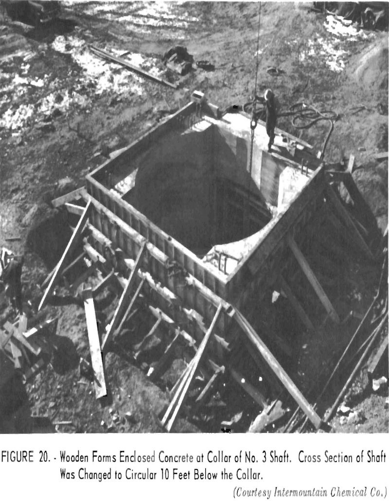
The concrete lining of the shaft was poured in 45-foot sections. The lining has, a minimum thickness of 12 inches where dry formations were penetrated and at least 18 inches where water-bearing formations were encountered (fig. 2.) Irregularities in rock walls keep sections of lining from slipping. The lining has an 18-foot inside diameter, except at the shaft collar, where the cross section was modified to provide room for ventilation equipment (fig. 20).
After sequences of drilling, blasting, and mucking advanced the bottom of the shaft about 48 feet below the bottom of the concrete lining (or 3 feet more than the 45-foot section to be lined), a round was drilled and blasted, and the broken rock was left in the shaft during concreting. The additional 3 feet provided space for expansion of rock broken by the last round. The top of the muckpile was shaped for alining and leveling a wooden template 45 feet below the bottom of the previous pour. The template was made in segments, which were bolted together at the bottom of the shaft. The template served as the bottom of the first set of forms; it had a wooden ring that held the
forms in a circle having an inside radius of 9 feet. The template was alined by two plumblines suspended from the previous pour. The alinements were checked periodically with four plumblines.
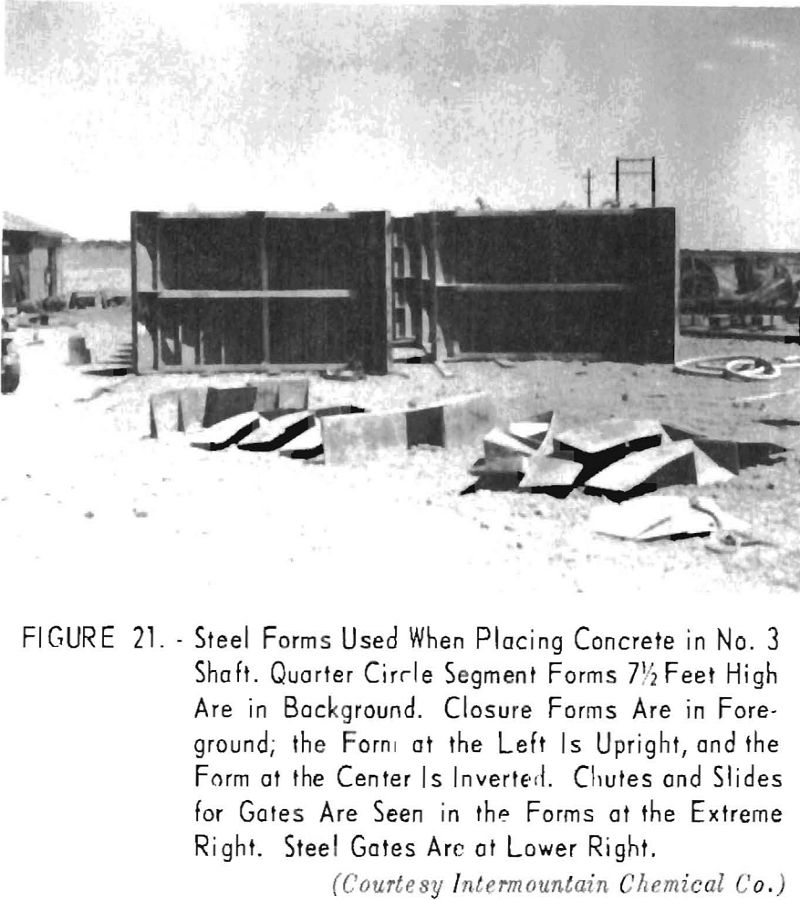
Ring-type forms were made of steel plate, ¼ inch thick, reinforced by ribs of 4-inch channels spaced vertically at intervals of 13-¼ inches (fig. 21). The forms were braced with plate across the back at the top, center, and bottom and with angles back to back. Each ring had four sections and two keys, which when bolted together formed a cylinder 7-½ feet high, having an 18-foot inside diameter.
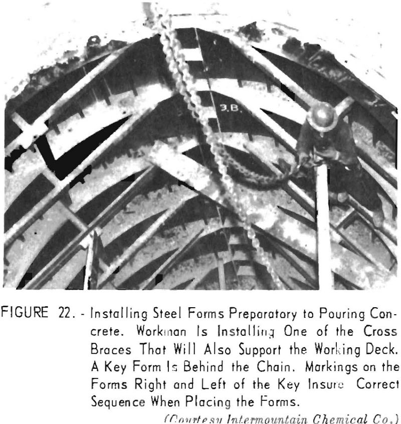
Keys facilitated detaching the forms from the concrete. They were 9 inches wide and placed diametrically opposite each other when the forms were set (fig. 22). Shields for three sets of two ¾- by 4-inch expansion bolts were fastened to each ring with lag screws that went through the form and into wooden dowels in the shields. Expansion bolts were inserted in the shields after the forms were removed, and pipelines for air, water, and ventilation were suspended from them. Each ring had four triangular prisms with 18-Inch bases and 12-inch altitudes bolted to the outside of the plates. These protrusions formed bunton hitches for future installation of guides.
After the template was alined and leveled, the first set of forms was lowered into the shaft and bolted and pinned to the template. The tops of the forms were braced with four braces made of 6- by 3-½- by 3/8-inch angles placed back to back (fig. 22). The braces were pinned to plates welded to the top of the forms. A sectionalized platform made of planks and steel plates was clamped to the braces and formed a deck on which workmen stood while pouring concrete.
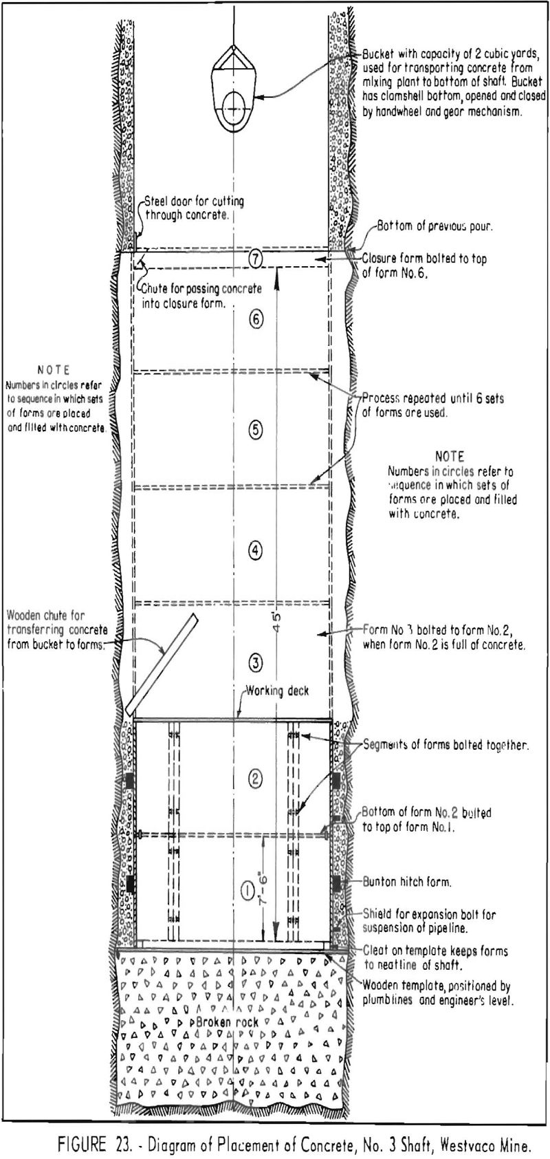
After the first form was filled with concrete, the next one was bolted to the top of it. The platform was hoisted and placed on braces at the top of the second form. The process was repeated six times while 45 feet of lining was poured (fig. 23). About 1 foot of space remained between the top of the sixth form and the bottom of the lining previously poured. This space was filled with concrete by bolting closure forms to the top of the uppermost 7-½-foot form. Closure forms were 12 inches high and had eight chutes, each 12 inches wide, spaced at regular intervals around its inside. Each chute had a sliding steel gate that was rammed down to cut off the concrete at the neatline of the shaft when the closure form was filled.
Concrete was lowered into the shaft in buckets of 2-cubic-yard capacity. The buckets had clamshell bottoms that were opened and closed by handwheels, which operated gears on the jaws of the buckets. The buckets discharged into wooden chutes, which channeled the concrete to the forms. Air-activated vibrators compacted the concrete placed behind the forms.
The entire concreting operation required about 12 hours for each 45-foot section. The pours averaged about 160 and 210 cubic yards where the lining had a minimum thickness of 12 and 18 inches, respectively.
Forms were stripped from the concrete 8 hours after the last concrete was poured. During this interval the crew removed some of the bolts from the forms, extended pipelines, and prepared for the next cycle. After the setting time for the concrete elapsed, the remainder of the key bolts were removed from the forms; and the forms were dismantled, hoisted to the surface, and cleaned and oiled in preparation for the next pour.
After the forms were removed from the shaft, the rocker shovel was lowered, and rock broken by the last round blasted before concreting was removed. The distance between the bottom of the newly poured concrete and the shaft was adequate to prevent damage to the concrete when the sequence of drilling, blasting, and loading was resumed.
Cement was delivered in tank trucks to the shaft site from Devil’s Slide, Utah. Aggregates were obtained from pits near Green River. During the winter, when temperatures fell as low as 40° below zero, the aggregates were heated by steam coils under the stockpiles. The temperature of the aggregates was maintained at about 60°, and that of the mixing water at 100° to 115°. A 50-hp. gas-fired boiler generated steam to heat the coils under the stockpiles and in the water tanks.
The concrete mix was calculated from screen analyses of the aggregates. One cubic yard of fresh concrete contained 588 pounds of cement, 1,250 pounds of fine aggregate, 1,880 pounds of coarse aggregate, and approximately 35-½ gallons of water. A resin additive was used to induce approximately 4 percent entrained air.
Because of variations in the sulfate content of the rocks penetrated and water encountered, two types of port land cement were used – Type II where the shaft was sunk through impervious shales and Type V where the sulfate content of the water percolating through sandstone was more than 1,000 p.p.m. The fine aggregate was clean, hard sand conforming to American Society for Testing Materials Standard C33-1952 Tentative. The coarse aggregate was hard, crystal¬line rock or gravel, graded 1- to ¼-inch, to conform to the same standard. Both aggregates were washed free of clay, loam, and other deleterious substances.
Slump tests were made during pours to control the quantities of water added; slumps between 4 and 5 inches in a 12-inch cone were permitted. Cylindrical samples for breaking tests were taken from each pour and submitted to laboratories of the University of Wyoming. Pressures of more than 4,000 p.s.i. were required to break most of the cylinders.
Drainage
As a precaution against influx of water, pump stations (9 by 8 by 7 feet) were excavated 450 and 900 feet below the collar of the shaft. A total flow of 10 g.p.m. seeped into the shaft, and pumps were not installed for this small quantity. Rings for collecting subsurface water were formed in the lining at 965, 1,101, and 1,266 feet below the surface. When the crew was drilling, the water was drained from the rings into a muck bucket and hoisted to the surface. The water that developed in the shaft and additional water from the surface were used to wet down the muckpile during loading.
Manpower
One crew worked one shift daily from late October 1955 to early January 1956 installing surface equipment and sinking the first 80 feet of shaft. Shaft sinking was continued two shifts dally from January 4 to February 3, 1956, and thereafter three shifts a day, 6 days a week.
To maintain a continuous sinking operation, it was not practicable to have special crews for each type of underground work. Drilling or mucking did not require 8 hours to complete; placing concrete required about 12 hours. As the time required for the various jobs did not correspond to an 8-hour shift, each crew drilled, mucked, or placed concrete, as the situation demanded, and frequently continued work begun by the preceding shift.
Each underground crew consisted of enough men to do the biggest job in the work cycle – drilling. Men on these crews worked underground most of the time, because surface work was fairly routine and required about the same number of men on each shift. A sinking crew consisted of five men and a shift boss. Surface crews consisted of a hoistman, crane operator, truckdriver, and topman. Two mechanics worked the day shift and one mechanic each of the other shifts. A superintendent, master mechanic, and clerk constituted the staff.
Equipment Maintenance
The jumbo, drills, and rocker shovel were cleaned and inspected after they were hoisted from the shaft at the completion of a work phase. Major repairs were made on the surface when the equipment was not being used, and minor repairs were made when necessary. The concrete forms were cleaned and oiled each time they were removed from the shaft.
Consumption of Materials
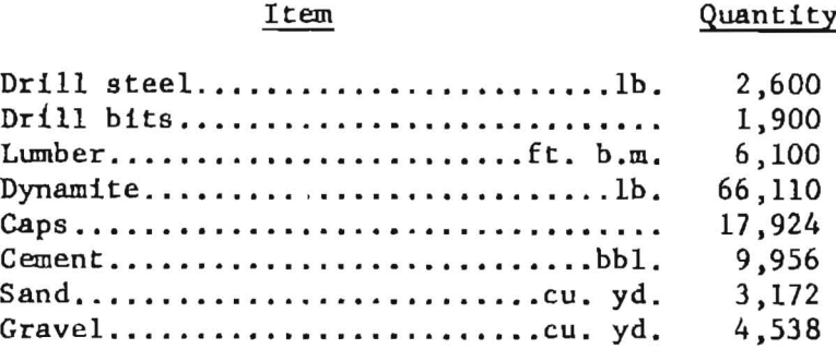
The quantities of materials consumed in sinking the shaft were as follows:
Rate of Advance
From February 3, to August 11, 1956, 1,327 feel of shaft was sunk and lined with concrete in three shifts a day. The best monthly advance was made in March, when 285 feet of shaft was sunk and 315 feet of concrete lining placed; 30 feet of the shaft lined in March had been sunk in February. The shortest time needed to sink and concrete a 45-foot section of shaft was 4 days.
Accident Prevention
Men operating relatively large equipment in limited space must be alert and well coordinated. The men were carefully trained to keep the machines under close control and to anticipate what other members of the crew were to do at all times. Safety meetings were held weekly and were attended by the workmen, the superintendent, and the shift bosses. Signs and posters reminded the workmen of hazards to their safety.
Accident-prevention devices included wire-mesh-enclosed ladder-ways on the headframe, steel-grid treads on stairways, guardrails around moving parts of machinery and openings in the decks of the headframe and concrete-mixing plants and the use of the carriage to cover the top of the shaft when loading or unloading equipment or supplies entering the shaft. The hooks on the cables from the mine hoist and crane and the hook on the tightline used for dumping the hoisting buckets had handles to prevent pinching fingers when hooking or unhooking the buckets.
