Table of Contents
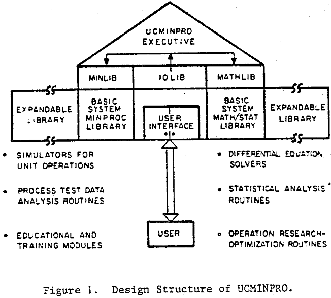
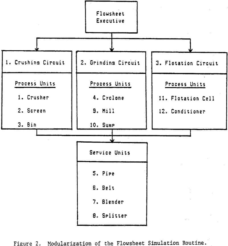
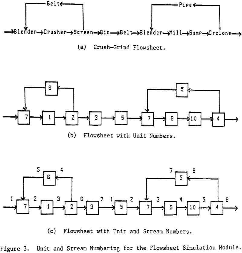
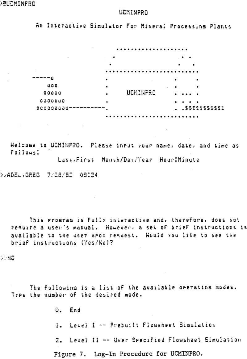
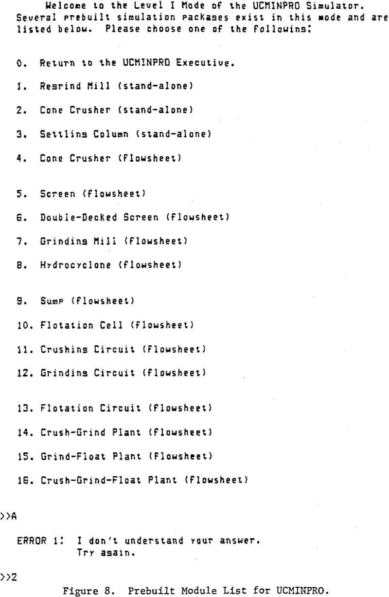
The fundamental design philosophy was based on meeting three criteria: flexibility, modifiability and usability. Flexibility refers to the ease of using the simulator to study a variety of flowsheets. A stream and unit operation numbering scheme was developed as a means of meeting this requirement. This scheme, in conjunction with modularized unit operation programs, made it possible to simulate various unit operations in almost any sequence. Modularity, along with the use of a structured design approach, was also responsible for achieving the second requirement, modifiability. This design approach made the incorporation of new modules a relatively easy task. Finally, usability was achieved through the use of an interactive design providing a self-guiding, self-documenting environment for the user.
Flowsheet Specifications
The primary feature of a general-purpose flow-sheet simulator is its ability to simulate a variety of flowsheet configurations without requiring changes in the program code. This feature necessitates a means of specifying the simulation order for the various unit operations and a scheme for labeling stream flows in the flowsheet. The UCMINPRO provides the general purpose by dividing the plant flowsheet into a number of circuit, each circuit in turn containing the necessary unit operations.
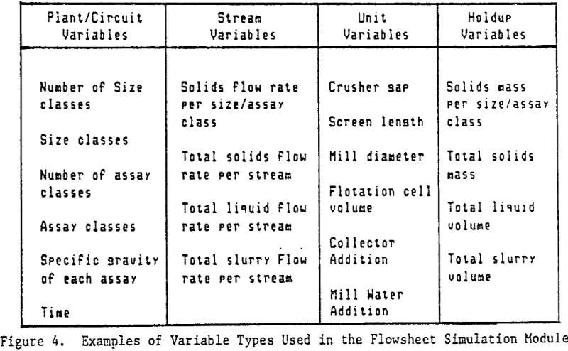
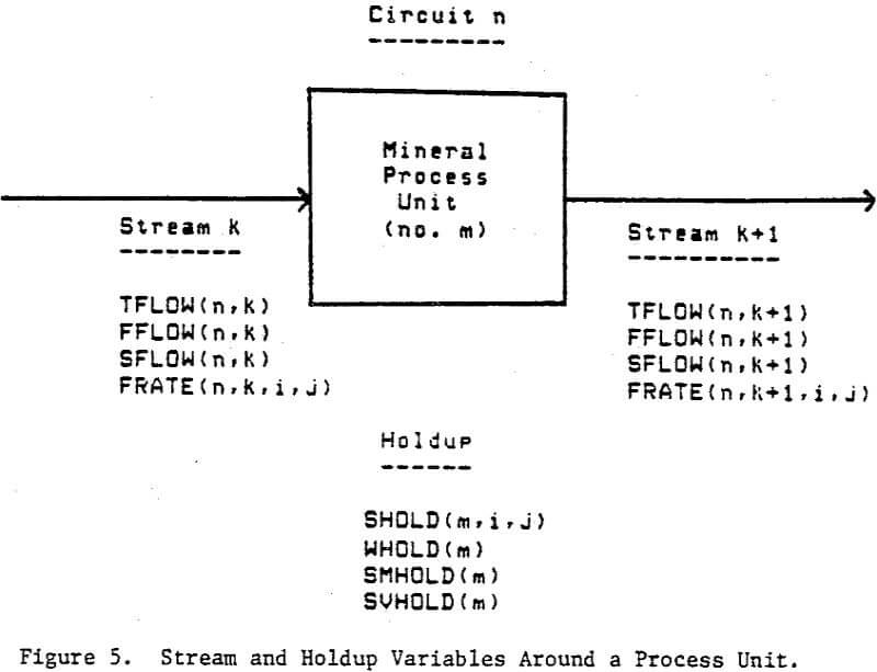
Within the simulator, it was necessary to identify four different types of variables; plant variables, unit variables, stream variables and holdup variables. Plant variables are items that are general to the entire plant and needed by every module. Unit variables are operating parameters and equipment sizes for the various units. Stream variables are items that must be passed from one unit to the next and are a function of time. Holdup variables are used to keep track of the internal state of a dynamic unit.
Unit Operation Models
In choosing models it was necessary that these models meet the following requirements:
- The models must describe the process or flowsheet adequately.
- The models must respond in the appropriate manner to changes in normal plant operating conditions.
- The models must be simple enough to run within the size and time constraints of a minicomputer.
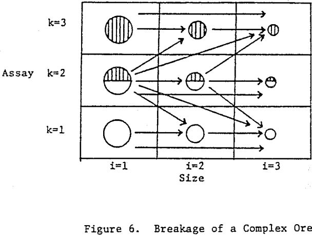
Whiten’s model assumes that the crusher can be divided into two zones; a breakage zone and a classification zone. Particles leaving the breakage zone are either classified out of the crusher or back to the breakage zone depending upon the size of the particle in relation to the closed side setting. This analysis results in a model of the form:
![]()
where f is the mass flow rate vector of the product,
fo is the mass flow rate vector of the feed,
B is the breakage matrix,
C is the classification matrix,
and I is an identity matrix.
Sample Simulations
To illustrate the utility of UCMINPRO for dynamic analysis, two sample runs were conducted. The first simulated the dynamic behavior of a grinding circuit, and the second combined the grinding circuit with flotation. Both cases demonstrate the technique by which the circuit is controlled through the interactive manipulation of operating variables.
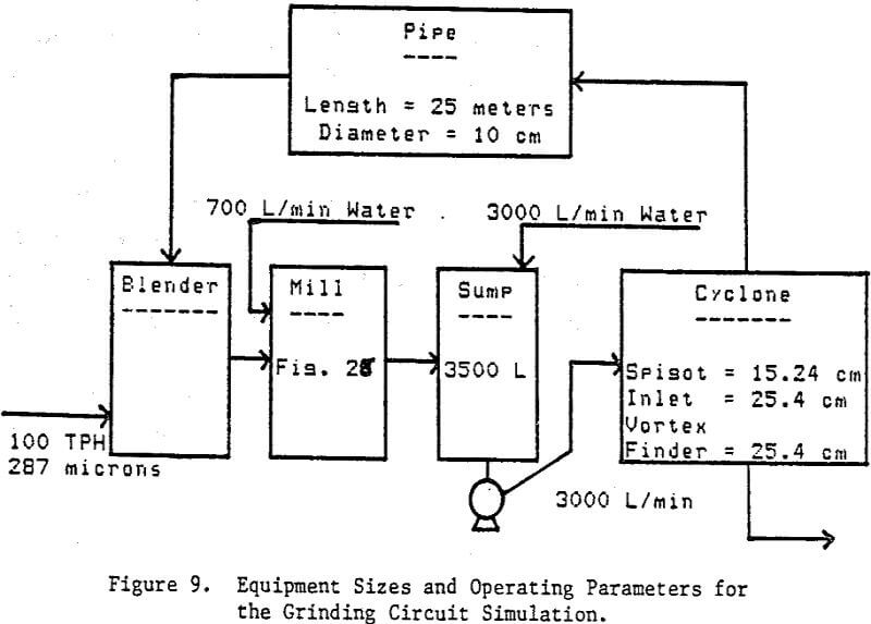
The grinding circuit simulated in this example is a typical closed-circuit grinding setup consisting of a mill, sump, and hydrocyclone. The pipe acts as a delay between the cyclone and the mill. The blender can be thought of as a conceptual rather than a physical unit required for the mathematical combination of streams.
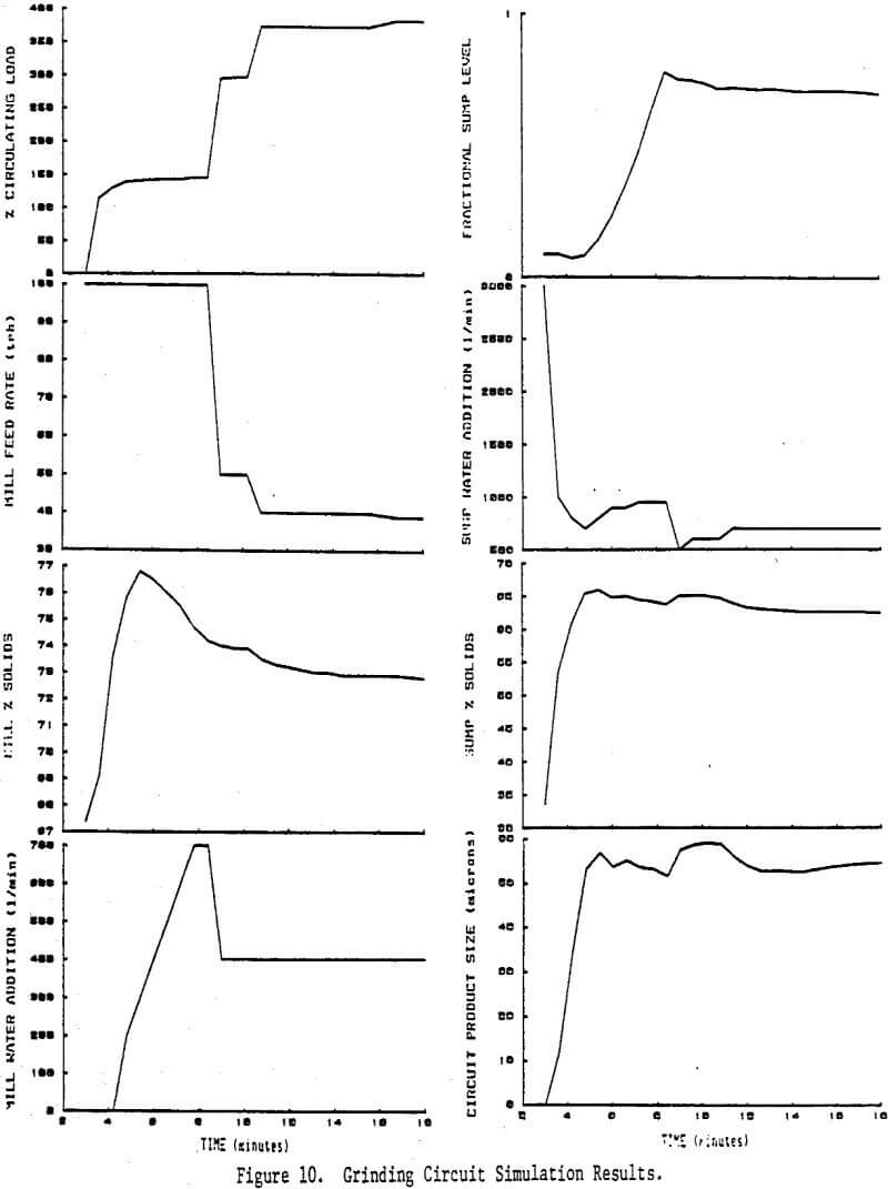
In this example, control action was taken by the user to maintain the circuit product size at 50 microns, the mill contents at roughly 70 percent solids and the sump at 70 percent full. This interactive control was provided for two reasons. First, a certain amount of control action was necessary to keep the sump from overflowing and to maintain reasonable operating conditions in the circuit. Second, this procedure demonstrated the educational aspect of UCMINPRO as a learning tool for dynamic analysis and control. Control action was provided through adjustments in mill feed rate, mill water addition and sump water addition.
Interactive control was once again provided with mill feed rate, mill water addition and sump water addition being used to control the grinding circuit. Flotation control was provided to maximize grade and recovery by manipulating reagent addition and aeration rate.
Two sample simulations, a grinding circuit and a grinding-flotation circuit combination, have been presented to illustrate the previously mentioned features and capabilities. It should be mentioned that in these examples, model parameters and input information were usually assumed or approximated. 