Table of Contents
Ideally, mill circuits should be controlled so that excessive random disturbances are reduced in frequency and amplitude. It is difficult to derive an objective measure of the effectiveness of any chosen control strategy. Often, the response of the circuit to pulse or sinusoidal disturbances is used as a measure of the effectiveness of control.
Linear Mill Models and Stochastic Control Theory
One approach to the problem of modelling dynamic systems subjected to random process disturbances is to postulate a priori that the system can be modeled by a finite set of linear, time invariant stochastic differential equations of the form
![]()
where Xt is the state variable vector and Wt is a vector of Wiener processes which form the basis for modelling process disturbances. A is the system matrix and D is a matrix of disturbance influences. Measurable outputs of the system described by Eq. 1 can be expressed as a linear function of the state variables
![]()
where Yt is the output vector and C is a constant matrix. The controller proportional bands and integral reset times will be imbedded in the elements of the matrix A. The statistical steady state variance matrix Vx of the state variables is given by the solution of the Liapunov equation.

where Ψ is the variance parameter matrix of the Wiener processes. The variance matrix of the system outputs is given by

Development of a Model for a Gold-Ore Milling Circuit
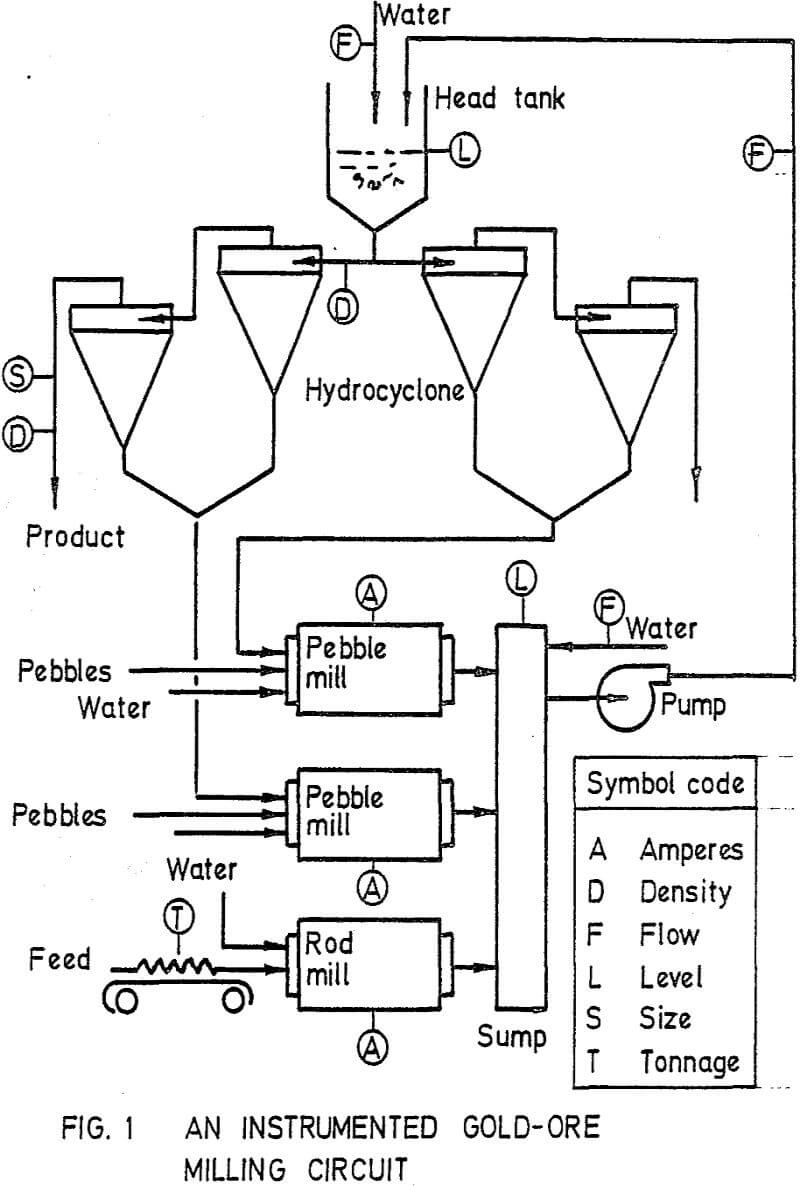
It was considered a milling circuit, which comprises a rod mill and two pebble mills discharging into a common sump. Pulp from the sump discharges to a head tank feeding two sets each of two hydrocyclones in series. On-stream instrumentation measures mill motor currents, product particle size and percent solids, water flows to head tank and sump, levels in head tank and sump, volume flow of pulp to the head tank and density of pulp feeding one of the primary hydrocyclones.
It was postulated that the volume flow of pulp from the discharge of these mills could be represented by an equation of the form
F1 = K1 (X1 + X2/σ – K2)n
where X1 is the mass of water in the mill and X2 is the mass of ore in the mill (excluding the grinding media of pebbles), K1, K2 and n are constants and σ is the specific gravity of the solids.
The rod mill was of an overflow discharge type and thus it was assumed that the volume of pulp in the mill would be insensitive to changes in throughput. The contents of the mill were taken to be fully mixed and the mass fraction of solids less than 75µm in the mill was represented by X4 in an equation of the form
![]()
where U4 is the mass flow of solids to the mill and W1 is the hold-up mass of solids. The pulp specific gravity was assumed to be constant. U5 is the mass fraction of solids less than 75µm in the feed and K4 is the grinding rate constant.
Application of Theory to the Design of a Control Strategy for a Gold-Ore Milling Circuit
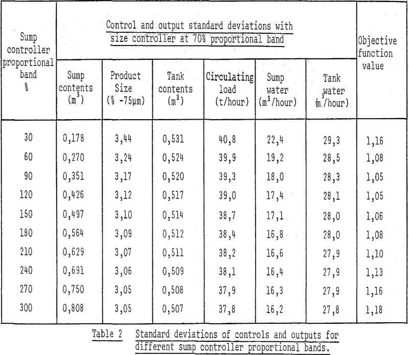
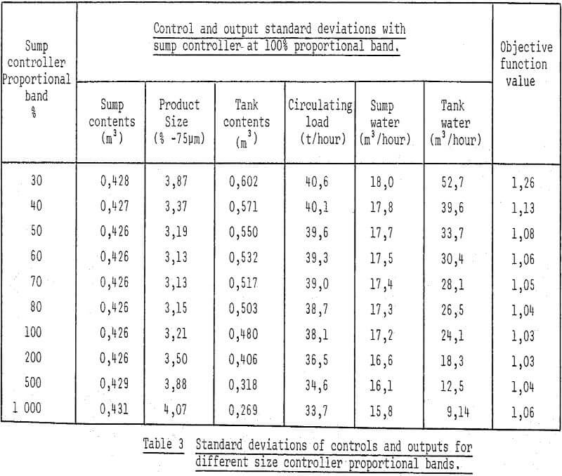
The results of the first two searches for optimal controller settings give the standard deviations of all controls and outputs of interest. The control of particle size by water addition to the head tank can aggravate the circulating load variance and hence also increase the probability of “roping” the hydrocyclones. The results of the analysis were substantiated by plant tests. Spectral analysis of data derived for several control experiments indicated that the strategy with the size and sump level loops significantly reduces the low frequency components of the product size perturbations, but at the expense of an increase in drifts of circulating load.


