Table of Contents
The philosophy behind the design and construction of the mobile conveying system is to allow flexibility and rapid movement or “mobility” of conveyors to follow the production face operations on a daily basis. During the conceptual stage, Foster Yeoman engineers were challenged to develop their own unique system to meet the rigid demands that the mobile crusher required. As is the usual case in mobile crushing systems, Foster Yeoman found that their application was “site specific” and had to develop their own design to match their special requirements.
The mobile conveyors and moving system had to withstand the rough quarry environment, which meant specifying robust design and failsafe hydraulic and mechanical equipment. Hatching the quarry’s operating requirements meant designing high throughput conveyors that were still light enough to be transported and adapted to variable ground conditions and face locations ranging from a few meters to nearly a kilometer away from the main quarry plant.
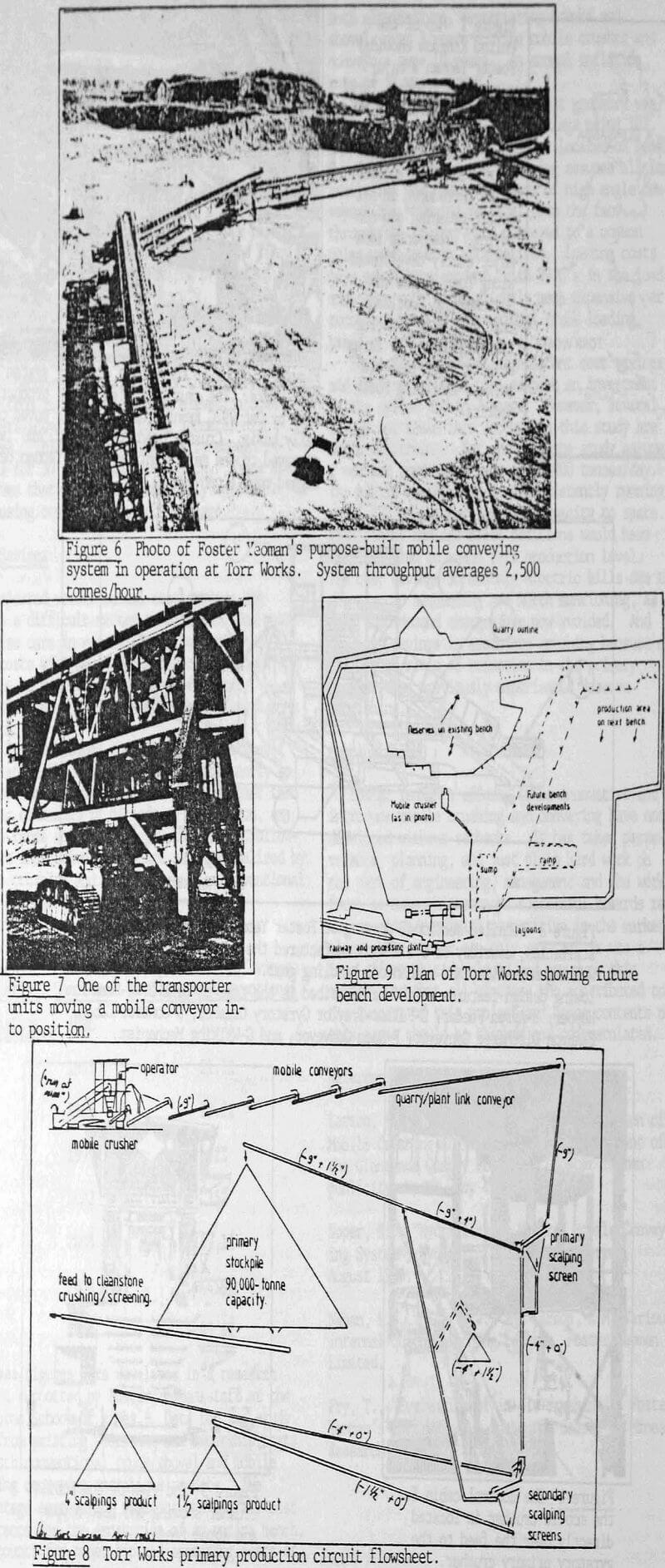
The solution evolved around the development of free standing 100 meter and 50 long conveyor bridges. Modular units were developed, light enough to be transported about the quarry easily and introduced to or removed from the inter-connected chain of conveyors as dictated by quarry face locations. A total of six 100 meter long modules, one 75 meter and one 50 meter long module are available at any time and in any combination to convey the rock from the mobile crusher to the fixed processing plant. A view of some of the mobile conveyors in operation is shown in figure 6.
Mobile Conveyor Construction
Each mobile conveyor structure consists of a tubular steel triangular lattice bridge, one large tubular member at the bottom, two smaller ones at the top with a 1.6-meter wide conveyor belt running between them. The belt uses 5- roller suspended garland-type rollers throughout with impact idlers at the tail end, and 2 roller return idlers. Modified sections at either end of the structure contain the lifting points used in moving the module, the support legs, and at the head end the conveyor drive, tensioning, switchgear and power transformer. The drive unit comprises a shaft-mounted gearbox, belt driven from a 132 kw motor. The weight of a 100-m nodule is 74 tonnes unloaded. Each conveyor has its own monitoring system that reports information to the crusher operator, such as belt speed, belt travel, lubrication, and power consumption. The belt speed is 3 m/sec and the modules are capable of conveying stone in excess of 3500 tonnes/hr. Average operating throughput in the system is 2500 tph.
Conveyor Transporters
The conveyor modules are moved independently but obviously follow the movements of the mobile crusher to new face locations on a daily basis. The physical movement is carried out by a pair of purpose-built transporter units, developed by Foster Yeoman. The transporters are broad, 5.2 m long by 4.4 m wide track units which combine a low-slung 113 kw diesel power pack, hydraulic system, and load carrying superstructure into a unit that is only 2.3 m high. This ensures stability while travelling loaded with a conveyor unit in the rough quarry environment. A conveyor is lifted for transport and supported by a mechanism that features an internally geared ball bearing slewing ring which carries a tilting/ rocking beam structure on large trunnion brackets. This arrangement best resembles a large universal joint. Two parallel lifting beams spaced 3 m apart from the top of this joint maintain contact with the conveyor module during transport. Tilting or levelling of the conveyor is controlled by horizontal cylinders on the superstructure, and free movement of the transporter about the conveyor when lifted (i.e., when pivoting or turning) is allowed by rocking bearings.
Movement of Conveyors
The mobile conveyor module and transporter become an integral hydraulic unit during the moving phase, linked by quick release couplings on the module’s hydraulic system. The moving phase commences with a transporter located at both ends of the module, each linked to the module hydraulically. The lifting mechanism of the transporter is aligned with the runway beams on the module, and the module is powered up a distance of 500 mm. The support legs of the module are raised hydraulically, and likewise the head of the conveyor is raised away from another module it was docked with by means of a hydraulic cylinder. The two transporters then operate in tandem to move the nodule to its next production location. This procedure is illustrated by the photo in figure 7.
Note that the lifting runway – or section of the conveyor module that contacts the transporter in lifting – has 4 meters of allowable relative travel at the tail end of the module. The head end transporter is fixed in its lifting position. This method of “one-free, one-fixed” module- transporter attachment allows each transporter to manoeuvre around and over obstacles, or even run at different speeds or even different directions without applying stress into the conveyor or influencing the other crawler. If each transporter were rigidly fixed to the module, the steel framework would be twisted like licorice during transport.
Conveyor Alignment
The required number of conveyors needed is chained in a series running from the discharge boom of the mobile crusher through to the fixed processing plant. Crushed rock flow resembles a cascading action, passing from one mobile conveyor to the next on its way to the plant. It is therefore critical to have a proper link tip between conveyors. This is accomplished by a hydraulic cylinder at the head or discharge end of each conveyor. This cylinder lifts or lowers the head to adjust it to the feed point of the following conveyor and compensates for any variations in ground elevation.
Once a conveyor is positioned and aligned it is set to the correct height by jacking the legs up when the transporter can be removed. Accurate levelling is facilitated by a simple pendulum device attached to one leg and independent control of each leg cylinder.
After the necessary number of conveyor modules have been positioned and linked, power and control cables are re-connected between conveyors and the system checked in readiness for the following shifts’ crushing and conveying operation.
The simplicity of operation and ease of use of the system is amply demonstrated by the time required to shut down, disconnect and move the conveyor nodules. Normally this will be less than that required to move the crusher to its new operating position and averages 3-4 hours. After electrical cable disconnection only three personnel are required, two drivers, plus a banksman responsible for overall alignment and co-ordination.