Table of Contents
The use of sieves to separate particulate material into fractions of various sizes has occurred throughout the period of recorded history. Sieving is one of the simplest methods of determining particle size distributions, and is probably used in industrial laboratories more than any other method. It is generally overlooked when carrying out fundamental research, which is unfortunate, since it can be a very accurate technique. Sieving has been classed along with optical and electron microscopy as a method which classifies particles according to geometric similarity, regardless of density or optical properties. Sieves with openings smaller than about 50 microns are seldom used for determining the size of dry powders. However, membranes having submicroscopic pores have been used to estimate the size of particles in colloidal solutions, and membrane filters with pore diameters of about 1 micron have been suggested for separating the particles in aerosols into two size fractions.
Types of Sieves
Most sieves which are used for Particle Size Distribution determinations have square openings. However, circular and rectangular openings, and even slits, are sometimes used.
Both the shape of the particle and the shape of the opening affect the size of particle which can pass through a given opening. For example, a particle in the form of a square plate can, in principle, pass through a square hole of side l if the length of edge of the plate is less than l √2. However, the probability of such a particle passing through such a hole when it is adjacent to the hole is quite small because of the small probability that the particle will be properly oriented. If a mixture of such platelets of various sizes is placed on a screen which is being shaken, a long time will be required for most of the particles approaching l √2 to pass through the screen.
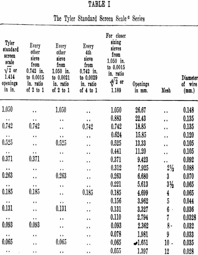
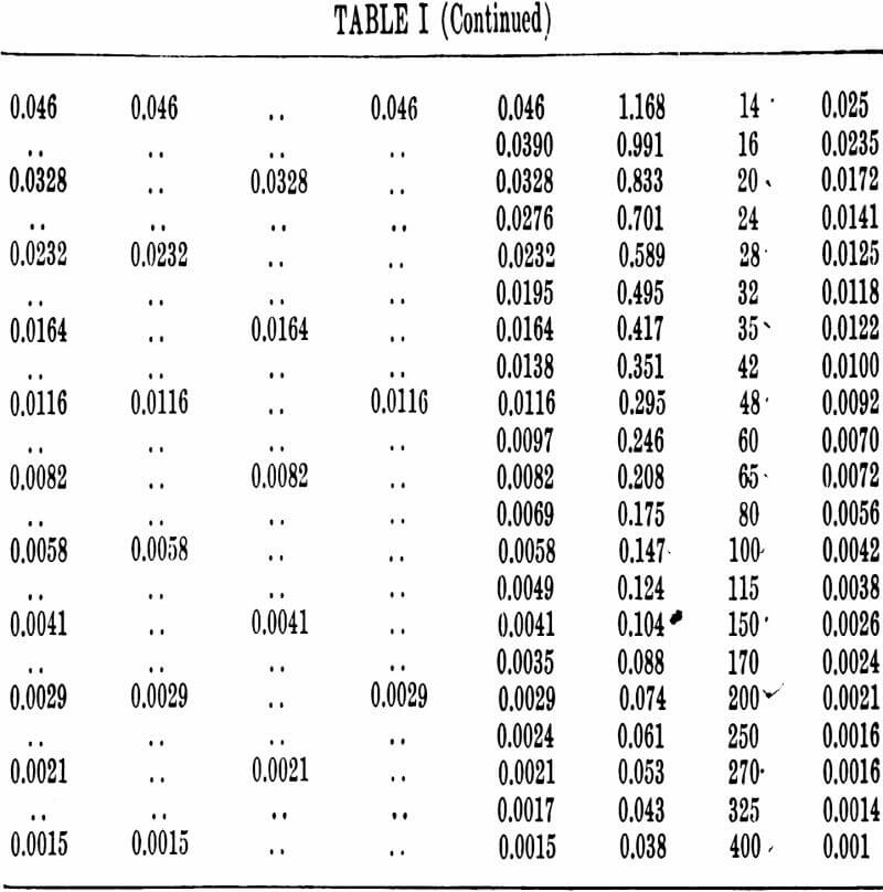
Fortunately, the sizes of screen openings have been standardized. Two standard series of screen openings are used in the United States. These are the Tyler Standard Screen Scale and the U. S. Sieve Series. The screens are made from woven wire cloth. The Tyler scale is based on the size of openings in wire cloth having 200 openings per linear inch (200 mesh). The diameter of the wire used for the 200-mesh screens is 0.0021 in. and the opening is 0.0029 in. (74 microns). The ratio between the adjacent sizes of the screen scale is √2. Thus the areas of the openings of each sieve are double those of the next finer sieve. Also, the ratio between the width of openings of alternate sieves in the series is 2. The Tyler scale also provides for closer sizing by means of a series of screens which have a fixed opening width ratio of 4√2. The Tyler scale is shown in Table I. Tyler screens are manufactured by the W. S. Tyler Co., Cleveland, Ohio.
The National Bureau of Standards in 1919 proposed a series using the same ratio as the Tyler Standard Scale Sieve Series, but based on an opening of 1 mm. The differences between the two series are so small that, for most purposes, sets of screens designed according to the two series can be used interchangeably. The U. S. Sieve Series is shown in Table II.
The British Standards Institution in 1932 adapted a sieve series known as the British Standard Sieve Series. The ratio is the same as for the U. S. and Tyler series and the openings are nearly the same. The slight variations are due to the differences between U. S. and British standard wire. Between 1907 and 1932 the British used a standard series adapted by the Institution of Mining and Metallurgy. There was no fixed ratio between the openings. Instead, the opening and wire diameter were the same. The screens consisted of 25% open area and 75% dead space. This proportion was used in the belief that this would minimize shifting of the wires.
However, such shifting is not a major problem when modern methods of manufacturing wire screens are used, and the series has been largely abandoned in favor of the British Standard Sieve Series.
The German Standard Sieve Series is identified as DIN No. 1171. The sieves are designated by number and also by the number of meshes per square centimeter. The French use a similar series designated as AFNOR.
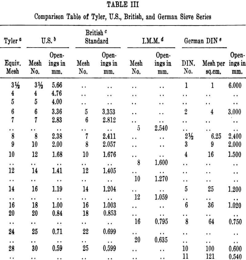
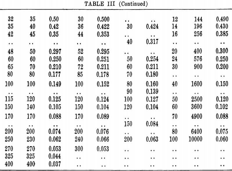
The Tyler, U. S., British, and German series are compared in Table III. Sieves of either the Tyler Series or the
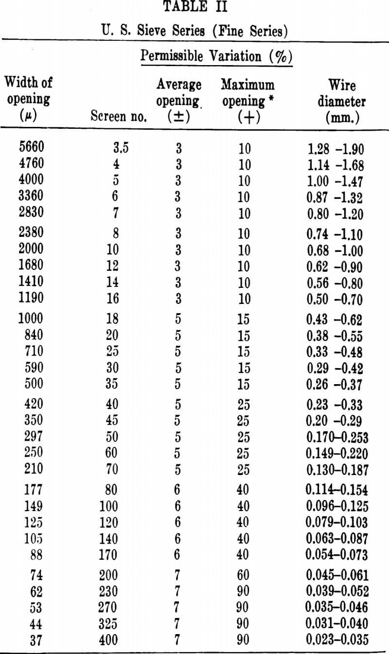
U. S. Sieve Series can be obtained commercially which have been certified by the National Bureau of Standards as coming within the specified tolerances. The sieves are tested by actual measurement of the wire diameters and openings.
The American Society for Testing Materials has set up standards for sieve cloth and frames. According to
these standards, the cloth is woven (not twilled, except the cloth of the 62-, 53-, 44-, and 37-micron sieves) from brass, bronze, or other suitable wire, and shall not be coated or plated. Frames for all sieves of the fine series (openings 5660 microns or less) are circular and are 8 in. in diameter, except that frames 3 in. in diameter may be used for sieves with openings of 149 microns or finer. The latter are used primarily in the testing of paint pigments. The height of the sieve from the top of the frame to the cloth is either 2 in. (full height) or 1 in. (half height).
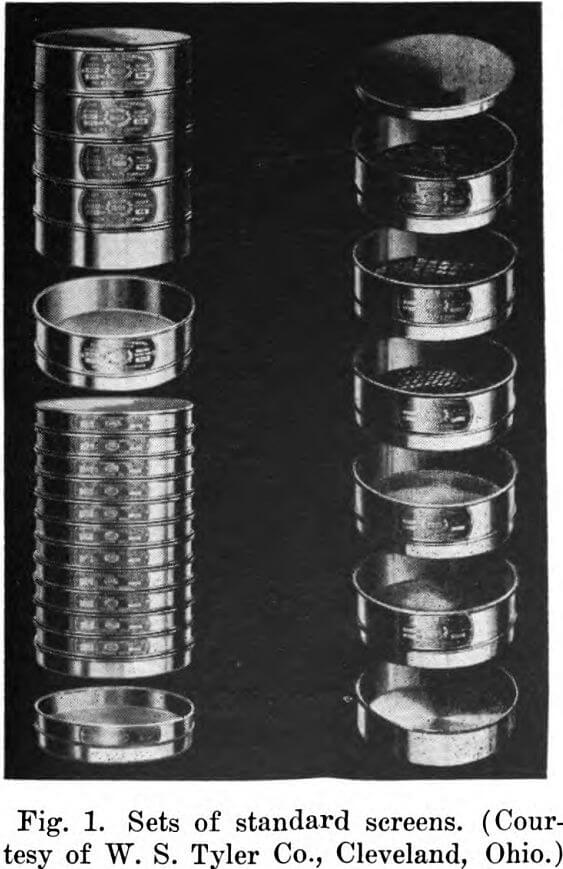
Sets of standard testing sieves are shown in Figure 1.
Methods of Making Particle Size Determinations
Determinations of particle size distributions using sieves usually involve placing a sample on the wire mesh of the top sieve of a nest of sieves, shaking for a predetermined period of time, and weighing the portion of the sample retained on each sieve. The sieves in the nest are of progressively finer mesh, so the weights of the portions retained on the screen constitute a set of classified particle size distribution data.
The weight of the sample screened is quite important. The weight of sample must not be too great, since oversize particles or even small particles may be jammed into the openings, clogging and distorting them. Also, the sieving time required to obtain reproducible results increases with increasing sample size. On the other hand, a sufficiently large sample must be used; otherwise accuracy is lost in both sampling and weighing. One hundred grams is often a satisfactory size when 8-in. diameter screens are used, and the fractions can be reported directly in percentages. A method which has been suggested for determining the optimum sample size starts by splitting out, with a sample splitter, samples of varying weights, for instance 25, 50, 100, 150, and 200 g. Each sample is sieved for the same length of time, for example 5 min., on a nest of sieves. If the three smallest samples (25, 50, and 100 g.) give the same results with the finer sieves, whereas the largest ones give lower results, 100 g. would be the preferred sample size.
The number of sieves used for a given determination depends largely on the reason for making the determination. If, for example, the only information required is the percentage of material less than a given size, a single screen is sufficient. If a particle size distribution must be obtained, five sieves is often a satisfactory number.
The sieving operation starts by mounting the sieves in a nest, the coarsest at the top. The sample is placed on the top screen, and the screens are shaken for several minutes. It is generally impossible to screen a sample completely; the longer one shakes the screens, the more material comes through, although to a continuously diminishing extent. Therefore, if the results of sieve tests are to be compared, the method of shaking and the time of shaking should be standardized. The screens can be shaken by hand, either all at the same time or consecutively. However, mechanical shakers produce superior results be- cause of their uniformity of action. The Ro-Tap shaker, manufactured by the W. S. Tyler Co., Cleveland, Ohio, is very popular in the United States (see Figure 2). It im-
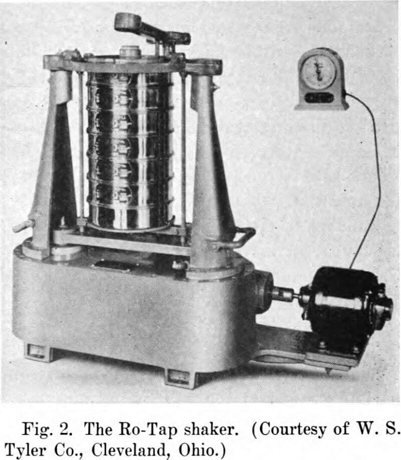
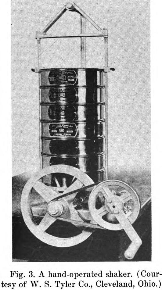
parts a circular motion to the nest of screens while tapping them from above. Portable shakers and hand-driven shakers, such as the one shown in Figure 3, are also available. High-frequency vibrators, such as the Hummer electric and the Leahy No-Blind screen, are also available.
Wet sieving techniques are of value for substances which tend to form aggregates during shaking, or which are already suspended in a liquid. Water or some other liquid is mixed with the material. The suspension is run through one or more sieves and additional liquid is poured over the residue. Sieves for wet testing are especially de-
signed with deep frames which prevent loss of sample when washing the fines through the sieve. Wet sieving is commonly used to isolate oversize particles. It usually greatly increases the total amount of material passing through the sieve. However, Sehweyer prepared closely fractionated samples of a number of materials which passed a number 325 sieve when dry but not when wet. Apparently the liquid breaks up aggregates and increases the agitation, but when added to an easily dispersed, closely fractionated sample it may increase the effective particle size.
The sieving time is somewhat arbitrary. It should be sufficiently long that the changes produced by continued agitation can be considered to be negligible. If accurate comparisons of various materials are to be made, the sieving time, sample size, screens, and method of agitation should all be standardized. Shergold studied the effect of sieving time and sieving load on the efficiency of sieving sand. The efficiency decreased slowly as the sample weight was increased from 125 to 500 g. and more rapidly as the weight increased from 500 to 2000 g. Shergold conchided that if the screens are not overloaded, that is, if the samples are between about 40 and 150 g., it is not necessary to prolong the sieving beyond 9 min. Weber and Moran state that enough time must be allowed for the fractions retained on the several sieves to approach constancy, but that a protracted time allows additional opportunity for the closely sized particles to seek out openings slightly larger than average in each sieve. They suggest that the period after which the greatest sieve fraction begins to lose a constant amount for each succeeding minute is the optimum period on which to standardize.
Details of the sieve analyses of a number of materials are given in the ASTM standards. An interesting procedure is that given for the sieve analysis for glass spheres used for highway traffic lines. Fifty grams of the dried glass spheres are placed on the screen with the smallest opening in the series designated for the test. The covered sieve is held with one hand in a slightly inclined position while tapping with the palm of the other hand at the rate of 150 taps per minute. The sieve is turned one-sixth of a revolution every 25 strokes. Sieving is continued until not more than 0.05 g. passes through the sieve in 1 min. of sieving. The residue is weighed and placed on the sieve with the next larger opening. Sieving is continued in a similar manner using each sieve successively in the order of increasing size of opening. The material is weighed and the percentage of the sample passing each of the sieves is calculated.
Calibration of Screens
Sieves are usually calibrated by measuring with a microscope a number of openings and wires. The results are then compared with the specifications, such as those of the U. S. Standard Series. The National Bureau of Standards recommends measuring the diameters of 5 to 10 wires, making four measurements on each wire. The number of wires per centimeter are then determined and the average opening calculated. Weber and Moran measured representative groups of five adjacent individual openings along two diameters of the sieve parallel to the warp and woof, respectively, taking the same number of measurements in each direction. They found that a total of 100 measurements gave calibrations reproducible within 1% on sieves coarser than No. 200. Two hundred measurements gave about the same accuracy for sieves No. 200 and finer. The average opening size (X) and the percentage standard deviation (100s/X) were calculated for each sieve. When the percentage standard deviation (Y) was less than 6, the sieves appeared to be satisfactory as judged from the results of sieving a number of standard samples. Moran and Weber suggested that when Y is greater than 6, the effective opening (Xt) for a shaking time of t minutes can be estimated using the empirical equation

Sieve calibrations based on empirical corrections determined by sieving standard samples were not satisfactory. The correction depended not only on the sieve, but also on the slope of the cumulative curve. Corrections based on equation (1) added little to the accuracy of results obtained for regularly shaped particles having a wide particle size distribution, but greatly increased the accuracy of results obtained for closely sized but irregularly shaped particles.
Equation (1) applies to plain-weave wire cloth but not twilled cloth.
The mesh of a sieve can be determined making use of “picket-fence interference”. A glass scale is used which is carefully ruled. The number of lines per unit length approximately equals the number of wires per unit length of the sieve. The graduation of the scale must be uniform and the number of lines per unit length accurately known. The lines and the space between the lines are about equal in width. To determine the mesh of a sieve, the scale is placed over the wire cloth and a bright light is shone through the sieve from below. Dark bands appear on the scale. The number of bands per unit length equals the difference between the number of wires and the number of rulings per unit length. The scale is then moved in a direction perpendicular to the lines. If this causes the bands to move in the same direction as the scale, the mesh is greater than the number of lines per inch, and vice versa. Moving the scale may cause some of the bands to move in one direction and some in another. In this case the number moving in each direction is counted and the algebraic sum is taken as the number of bands. The ASTM recommends that, for sieves with openings between 210 and 840 microns, the scale should consist of transparent lines about the width of the wire diameters ruled on an opaque background. The glass scales can be obtained from the Bausch and Lomb Optical Co., Rochester, New York, and the Keuffel and Esser Co., Hoboken, New Jersey.
Sieves can be sent to the National Bureau of Standards to determine conformity to specifications.
Treatment of Results
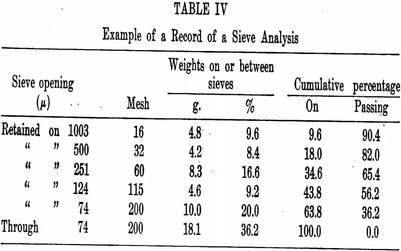
The results of a sieve analysis are often reported in tabular form, as shown in Table IV. Cumulative percentages, in addition to percentages and weights retained on each screen, may be reported. When large numbers of sieve analyses are being made, standard forms for reporting the data are a great convenience. These can be printed or mimeographed on special order, or can be obtained from commercial sources.
The results obtained by sieving can be considered to be classified data in which the class intervals as usually expressed are not the same size, but differ by a constant ratio. However, if the class intervals are expressed as differences in the logarithms of the screen openings, they do have the same size. Histograms can be prepared which use a logarithmic scale for the abscissa.
The results of sieve tests are usually plotted as cumulative curves. The ordinates may be linear or probability scales, and the abscissas may be linear or logarithmic scales. Graph paper prepared especially for recording the results of sieve tests is commercially available. The linear graph paper has the ordinate ruled into 100 divisions representing percent, and the abscissa is divided by lines placed so that the distances of any two successive lines from the origin are related by the factor √2. Thus the rulings on the abscissa can be made to represent any set of screens chosen from the U. S. Standard or Tyler series. Similar paper is available for the closer sizing ratio 4√2. The semilog paper
has the same type of ordinate as the linear paper, but the abscissa is a logarithmic scale which, in addition to the usual markings, has markings representing screen openings. This scale has the advantage over the linear scale that it compresses the curve for the coarse sizes and extends it for the small sizes.
The use of probability paper for making cumulative plots was discussed in Chapter II. Whenever the data can be represented by a straight line on log probability paper, plots of weight distribution can be transposed to plots of surface and number distribution. The mean diameters of these distributions can be calculated from equations 27 and 28 of Chapter II. The application of the Rosin-Rammler relationship to determining particle size distributions by sieving was also briefly discussed.
Krumbein has proposed the use of the following transformation when plotting the results of sieve tests:
∅ = — log2 d…………………………………………………………….(2)
where d, as usual, is the particle diameter and is measured in millimeters. Since the U. S. and Tyler Standard sieve series are such that the ratio of successive mesh sizes is √2, the use of 2 as the logarithmic base has the effect that values of ∅ for successive mesh sizes differ by 0.5 and for alternate mesh sizes by unity. The resulting scale is one of integral numbers. There is some advantage in using a linear scale of ∅ rather than a logarithmic (base 10) scale of d.
Compare Methods of Particle Size Analysis
Sieving methods for determining the size distributions of materials consisting of particles over 50 microns in diameter have great advantages over almost any other method. The results are capable of high precision, although they are somewhat empirical, since the results obtained depend somewhat on the method and time of shaking. Schweyer’s study of five materials closely fractionated by sieving was discussed in Chapter III. He found that the mean microscopic diameters varied from 1.2 to 1.5 times the sieve aperture, and from 1.1 to 2 times the equivalent sedimentation diameter, depending upon the material. Traxler and Baum (7) and Fritts (8) found that the 325-mesh sieve, which has an aperture of 44 microns, just passes particles of about 45 microns diameter. It had previously been assumed that the largest particle passing a 325-mesh sieve would have an average diameter of about 60 microns, because a square opening 44 microns on a side has a diagonal of about 60 microns. Heywood studied the relationship of length, breadth, thickness, and volume of particles to the size of the sieve aperture through which the particles would pass. He found that the breadth of the particles is most closely related to sieve aperture size.
Sieve analyses generally require little time. A complete sieve analysis often can be made in a half hour or less, as contrasted with a determination of size distribution with the optical or electron microscope, which may require an entire working day. Much less skill is required to make sieve analyses than most types of particle size determinations. All that is required is the ability to use a simple balance and to follow a brief set of directions. The equipment is relatively inexpensive. Another advantage of sieve tests is that the materials are physically separated into fractions according to size, and these fractions can be studied individually.
The main drawback to sieve tests is that they cannot be used for particles much smaller than 50 microns. This results from the difficulty of weaving wire cloth having uniform openings of such small sizes.
