Table of Contents
- Rotary Jaw Hard rock Crusher Concept
- Summary of Rotary Jaw Crusher Advantages
- Rotary Jaw Crusher Principle and Model Performance
- Feed Systems
- The Scale Model
- Scale Model Performance
- Conclusion of Model Tests
- Prototype Design
- Basic Rotary Jaw Crusher
- Crusher Feeder Systems
- Elevating Chain Flite Conveyor
- Discharge Systems
- Site Geometries
- Crusher Operation
- Performance Specifications
- Commercial Components
- Updated Applicability Assessment
- System Specifications
- Performance Specifications
- Equipment Cost
- Operating Costs
- Installation Procedures
- The Market
- Phases II and III Program Plans
- Phase II Construction and Surface Test
- Phase III, Underground Test
- Phase III Goals
Comprehensive underground hard rock mining studies pointed out that significant reductions in ore handling costs could be attained if portable, low headroom, hard rock crushers were available to permit economical belt haulage from temporary locations close to production sites. Prompted by these reports a specific “Application Study of Portable Jaw Crusher” was initiated to quantify the industry needs, examine available equipment and to provide a suitable crusher concept if necessary.
Major conclusions of that study were:
- There is a need for a compact, portable, underground hardrock crusher, with the major constraint on size being height
- Maximum crusher dimensions, including provision to feed the machine, should be about 7 to 9 feet high by 8 feet wide by any reasonable length
- Total throughput should be 100-300 tons per hour
- Critical feed opening size for the low profile machine should be about 30 to 36 inches
- Discharge size should be minus 6 to minus 8 inches.
Rapidex did conceive a novel “rotary jaw” crusher design which meets these requirements. Prototype design of such a machine, and tests of a scale model rotary jaw hardrock crusher are presented herein.
Rotary Jaw Hard rock Crusher Concept
Following a thoughtful examination of conventional crusher designs the essential characteristics of successful hardrock crushers were delineated and from this understanding the rotary jaw crusher was conceived. It is in essence a highly curved jaw crusher geometry permitting some reduction in basic jaw height and, more importantly, providing for a horizontal feed into the jaws. Feed enters at the top of the jaws, travels through roughly 120° of arc in a curved converging space between two jaws, and exits at the bottom of the jaws. The concept permits a design within the foregoing specifications.
As described in detail in Sections 2 and 3, the concept further results in an extremely simple and rugged machine.
Model Performance
The novelty of the rotary jaw crusher concept suggested that a model “proof of concept” test be undertaken before commiting major funding to a full scale prototype. Of particular concern was the ability to force material horizontally (i. e., without the gravity feed of a conventional jaw crusher) into the inlet region of the curved jaws.
A one-quarter size model, having true hardrock capability, was designed, fabricated, and demonstrated along with two candidate feed systems. The model demonstrated the expected smooth operation of a fully balanced design and it verified the design throughput. Further interesting and desirable operating characteristics are described in Section 2.
Prototype Design Specifications
Based upon model test data and the Phase I design effort, prototype specifications and performance will be as follows:
Inlet – 30 x 48 inches
Discharge – minus 6 inches nominal, adjustable 4 to 8 inches
Throughput – 200 to 250 tons per hour (400 TPH with scalping)
Installed power – 125 horsepower
Feed systems – elevating chain conveyor or vibratory feeder
Discharge systems – chain conveyor or rubber belt conveyor
Machine height 8 feet 0 inches (minimum option with chain discharge) 9 feet 7 inches (or somewhat less) with rubber belt discharge
Width 9 feet 4 inches (for 400 total TPH)
Length 3 5 feet (including typical feed hopper)
Weight 57 tons (including typical feed hopper) 12. 5 tons (heaviest single component to be moved)
Regarding portability, a typical conveyor move-up of about 400 feet is expected to take one or two shifts. Little site preparation will be required, although in low headroom situations some operators have expressed a preference for modest site excavation in order to avoid the costly chain discharge conveyor required in the lowest profile machine configuration.
A one-shift moveup is possible if virtually all main conveyor extension tasks can be accomplished prior to moveup. Obviously, a less easily extendable conveyor could cause the moveup to consume two (or more) shifts, irrespective of the portability of the crusher.
Summary of Rotary Jaw Crusher Advantages
Based upon Phase I design work and highly successful model tests, the rotary jaw crusher advantages may be summarized as follows:
- A truly low headroom configuration with horizontal feed
- Proven rugged hardrock crushing action similar to that of conventional jaw crushers
- Extreme simplicity of design
- Smooth, fully balanced rotary motion – easy on foundations in comparison to reciprocating jaw designs
- Excellent slab breaking characteristics
- Completely non-choking action – can even run without harm with the discharge blocked
- Apparent uniformity of discharge size (qualitative observation, not based on quantitative measurement).
Rotary Jaw Crusher Principle and Model Performance
Basic Hardrock Crusher Design
Among conventional crusher designs only jaw and gyratory crushers are truly satisfactory for hard abrasive rock. Following the observations of the Applications Study, these crushers in comparison to all other types, are distinguished by three fundamental characteristics:
- They are stronger. Aside from obvious connotations, this characteristic means that successful hardrock crushers contact rock only with broad, extremely blunt surfaces.
- Their crushing action utilizes a limited movement relative to the rock surface – a movement that is very small in comparison to feed size.
- They possess a feed means that absolutely prevents advance of any rock fragment to a position that would require a large deformation.
Figure 1a illustrates the principle of a simple (i. e., straight) jaw crusher. Rock fragments are fed into the top of a converging passage between two jaws. Fragments move downward between these jaws, fed by gravity, as one jaw oscillates through a small motion (for example, a peak-to-peak amplitude of the order of 1 inch for the 30 inch machine shown) relative to the other. Fragments fall forward as the jaws move away from one another, are trapped in the conveging passage, and crushed there as the jaws move together again. The angle of convergence between jaws is somewhat variable but generally it is about 20°. For greater angles it is likely that fragments will be simply squeezed back out towards the inlet rather than (frictionally) captured and crushed. It follows then, that for a 30 inch opening and a 6 inch discharge, as desired for the subject application, a conventional set of jaws must be roughly 69 inches high as shown.
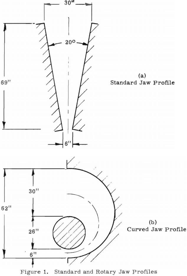
Figure 1b illustrates in similar schematic form, an equivalent rotary jaw crusher. The central path through the crusher is simply wrapped through a reasonably tight curve – an arc of 180 for the case shown. The dimensions shown are equivalent in the sense that the inlet and discharge openings are the same and the mean path length is the same – hence the mean convergence angle between opposing jaws will be the same, as will be the ability to capture and crush fragments. A net saving in jaw height is indicated, though the difference is not large. More importantly, the rotary jaw crusher accepts horizontally fed material whereas the standard jaw crusher must be vertically fed. This allows a significant saving in overall headroom required, particularly when one must handle slabby material which would orient itself along the crusher centerline.
Presumably, oscilation of either jaw of the rotary jaw crusher would work, but we have chosen an orbital motion of the cylindrical or inner jaw element, as shown in Figure 2. The inner jaw is a cylindrical shell freely rotatably mounted (i. e., not rotationally powered) on a rotating eccentric shaft. This form was chosen for three major reasons:
- It is simpler and much more easily constructed than an oscillating outer jaw design.
- Being a purely rotary motion, moving parts can be easily and precisely counterbalanced for smooth running.
- With rotation of the drive shaft in the “forward” direction (as shown) the orbiting shell moves through the crushing zone so as to provide a peristaltic pumping action to enhance throughput.
In effect, the inner jaw moves through the crushing zone in wave like fashion (the peristaltic pumping motion). It then provides two additional advantages over conventional practice. By crushing only in a local zone which moves through the material, peak crushing forces are reduced in comparison to a standard motion (i. e., the Blake type jaw crusher) which crushes everywhere at once. Also because of this local crushing action, lateral relief is afforded for the trapped material. This relief, at least in part, leads to a highly favorable reduction in choking problems as described in Section 2.2. It may also contribute to the apparent tendency of the rotary jaw crusher to produce an unusually uniform product.

Non-Choking Outer Jaw Design
The “exact” equivalent (i.e. to the straight jaw crusher) rotary jaw crusher would have a uniform convergence angle between inner and outer jaws. With a cylindrical inner jaw that means that the outer jaw would be drawn at a constant angle to a local radial line from the shaft center. Such a curve is called a log spiral.
Actually, a practical rotary jaw crusher would not be constructed in this fashion, just as conventional jaw crushers are not constructed with straight jaws. Instead, the jaws are curved in a “non-choking” profile that tends to decrease (but not prevent) choking.
Briefly, choking and the design of non-choking jaws may be described as follows, taking the conventional jaw crusher as a simpler example. Consider a fragment (spherical for simplicity) that is just captured locally as the two jaws are closest together. If the jaws now move apart, the fragment will move downward to a (calculable) new position as the jaws reach maximum separation. As the jaws close again, the fragment must now be crushed. That forward movement per cycle of the jaws is roughly the distance any local packet of material will move ahead after each crushing stroke. If the jaws are straight, and if the oscillating stroke is uniform over their length (it isn’t, but we shall consider the simple case for clarity) each packet will move ahead the same distance per cycle throughout the crusher. Consider the volume occupied by such a packet as it progresses through the jaws, say per unit jaw width (into the paper in Figure 1a). The length of the volume (parallel to flow) will be constant since each packet moves ahead the same distance per stroke, but its width must decrease as the jaws converge. Hence the volume of a packet must decrease, and its density increase, as the material travels through the jaws. If the density increases until the material is packed solid the crusher is said to be “choked” since no greater throughput can be tolerated. Worse than that, as choking is approached, crushing forces rise to excessive levels. Obviously a straight jaw machine would choke first at its throat or position of minimum opening between jaws.
To avoid choking a “non-choking” design seeks to maintain the volume available to each packet of material as it moves through the machine. With the walls necessarily converging, this can be done by increasing the length available as the packet moves forward between strokes: that is, by decreasing the local angle of convergence. Hence non-choking profiles are curved to present a decreasing angle of convergence from top to bottom. Graphical methods are available for such profile designs. Obviously, for a given maximum allowable convergence angle (determined by friction coefficient) and desired inlet and discharge openings, a non-choking design must be taller than a straight jaw design. In practice a compromise is often selected, having either a larger than optimum convergence angle at the inlet to compensate for the decreasing angle further on or a smaller inlet opening. Increased inlet angle tends to decrease the feed capability of the top portion of the machine, but in conventional practices this is insignificant since the limiting condition occurs at the throat.
Though perhaps not as easily described, an analogous design procedure can be used to define a “non-choking” profile for the outer jaw of the rotary jaw crusher. This was done, and the test model incorporated such a profile. As with the standard jaw crusher, use of a non-choking profile produces an increase in convergence angle at the inlet which, in turn, tends to retard feed in that area.
Upon test, the rotary jaw crusher proved to be spectacularly non-choking. It displayed no sign of plugging or excessive force levels with increasing throughput. In fact, the discharge could be deliberately plugged while the inlet was still force fed with no apparent adverse effect. This seemingly happy result is not entirely desirable: as noted above, non-choking performance is gained at the expense of feed rate in the inlet. Although the rotary jaw model exhibited acceptable throughputs, it would nonetheless be advantageous if this could be increased, and it is believed that this can and should be done with a new profile that favors the inlet region relative to the throat.
There are believed to be three reasons why the rotary jaw crusher model was so choke free, and only one of these has to do with the non-choking outer jaw profile. The rolling local crushing action of the orbiting inner jaw provides relief in both forward (i. e., the throughflow direction) and backward directions for excess material in the immediate crushing zone. This should delay the onset of choking and it would tend to minimize the adverse effects of choking when it does occur. Also, the curved flow path of the rotary jaw crusher orients the normal choke point (i. e., the choke point anticipated in the model design) in an essentially vertical direction where gravity and the peristaltic pumping action combine to assure high throughput. Conversely, the conventional non-choking design procedure penalizes the inlet region where only the peristaltic pumping effect acts to push material forward. Thus penalized, the inlet is not capable of providing a throughput sufficient to cause choking at the normal throat no matter what the throat profile. It seems clear that, even though demonstrated throughput was adequate, a more balanced profile favoring the rotary jaw crusher’s unique inlet geometry would be well worth trying.
Feed Systems
Two feed systems were tested in the scale model tests, corresponding to two possible prototype configurations. For lowest headroom and for low discharge haul vehicles an elevating chain conveyor feed is necessary. Because chain conveyors are high maintenance components in abrasive rock applications, many mines would prefer a vibratory feeder (or a simple gravity chute if headroom and haul vehicle discharge permit).
Elevating Chain Conveyor and Ring Bar Grizzly
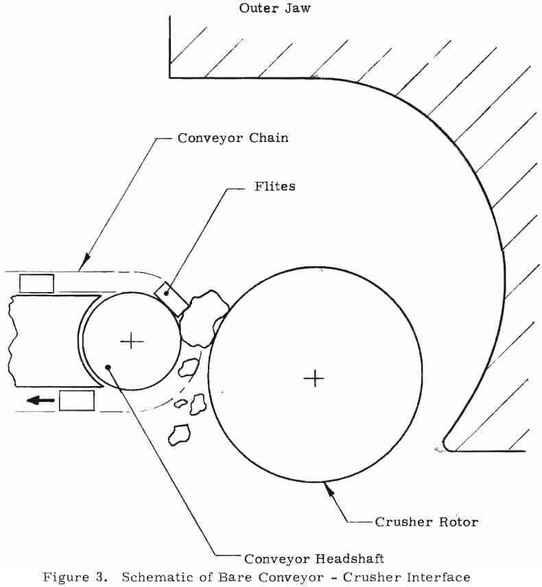
Hoppers discharging via a chain conveyor are common, and in fact elevating arrangements are not unusual. However, a chain conveyor discharging roughly horizontally to the orbiting center jaw of a rotary jaw crusher does present some new problems. For minimum height, one cannot drop material into such a conveyor from above. It is then necessary either that the conveyor discharge be close enough to push material directly into the crusher inlet or that the conveyor discharge on some sort of short bridge element that reaches between conveyor and crusher. In the former (direct feed) case there is danger that material falling from the conveyor will be trapped or pinched in the cusp formed between the conveyor headshaft and the cylindrical crusher jaw, as shown schematically in Figure 3. Forces acting on such pieces, either as a result of the pinching geometry or from active motion of the orbiting jaw, could place excessive loads on the conveyor headshaft and/or structure. Of course some open space between the headshaft and the crusher jaw is desirable in order to permit fallout of undersize material in a grizzly action.
Although the bare conveyor – crusher connection provided satisfactory throughput (see Table I), it is feared that forces transmitted from the crusher through rock fragments to the conveyor will ultimately decrease conveyor life. After trying several simple bridging elements
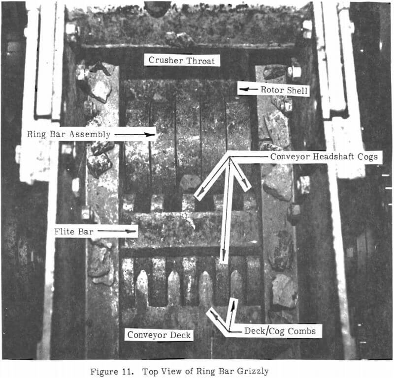
the “ring bar grizzly” shown schematically in Figure 4 was shown to provide the desired isolation while maintaining excellent throughput. The ring bar grizzly consists of a stationary bar carrying a series of very loose steel rings as shown in Figure 4 (see Figure 11 for a top view of the rings). Material passes from the conveyor, over the rings, and into the crusher inlet. Undersize material may fall out in either of the two gaps between elements. The multiplicity of loose rings and the proximity of the orbiting inner jaw provides considerable agitation that enhances undersize fallout and at the same time minimizes the likelihood of a “hard” connection between crusher and conveyor. The increased conveyor-to-crusher spacing does decrease the ability of the conveyor to force feed the crusher, but adequate throughputs were demonstrated with apparently no adverse loading on the conveyor headshaft.
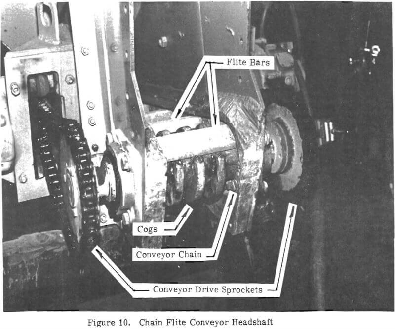
Figure 4 indicates that the headshaft was provided with cogs which were sized to “hide” conveyor flites as they moved over the headshaft. This was done to eliminate any tendency of the conveyor flites to forcefully drive material downward between the headshaft and crusher or between headshaft and rings. To minimize the danger of trapping material beneath the flites, the cogs were actually a series of elements spaced across the headshaft, as may be seen in the photograph, Figure 10. This headshaft design seemed to function without mishap.
Vibratory Feed Conveyor
To demonstrate vibratory conveyor feeding, a simple feeder was fabricated and attached as shown in Figure 5. This device vibrated normal to the deck surface and thus had to be tilted downward to provide feed. A standard vibratory feeder, having a horizontal vibratory component as well, could feed horizontally into the crusher.
The Scale Model
Having seen the basic crusher concept and features of its feed systems, let us examine the actual experimental hardware. A one-quarter size model was constructed, having a 7½ by 12 inch inlet and a 1½ inch discharge (adjustable). The center jaw was 7 inches in diameter and mounted on a 1/8 inch eccentric (¼ inch throw). The outer jaw was contoured to be non-choking as described previously. The shaft was driven at a variety of speeds (provided by a series of different pulleys) by a 20 horsepower 1800 rpm motor. Overall construction was very rugged to provide realistic hardrock testing.
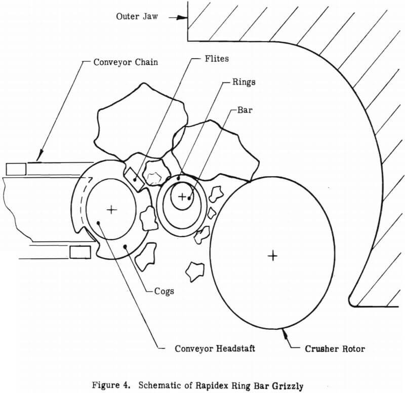
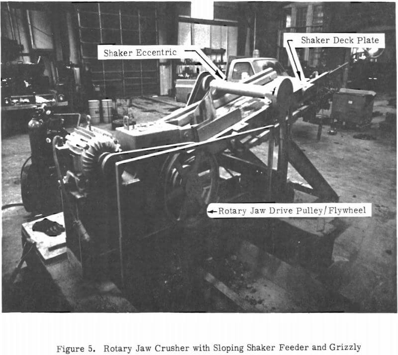
Figure 5 was a drive side view of the crusher, with the vibratory feeder attached. The “V” belt drive (and guard rail) are easily seen, but the solid structure of the basic crusher effectively hides all crusher internal details.
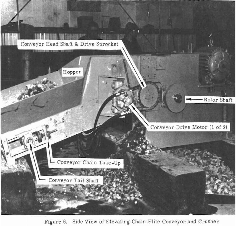
Figure 6 is a view from the opposite side, this time with the model hopper-feeder attached. Although crusher internal details are again hidden (this time by the conveyor frame) certain conveyor features are visible and worth noting. Note the pile of “scale” muck in the hopper; the conveyor drive motor(s) (pneumatic), chain connected to the head- shaft; and the standard chain take-up adjustment.
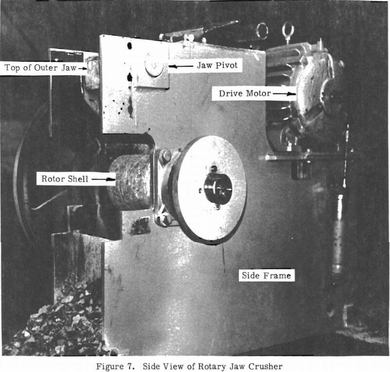
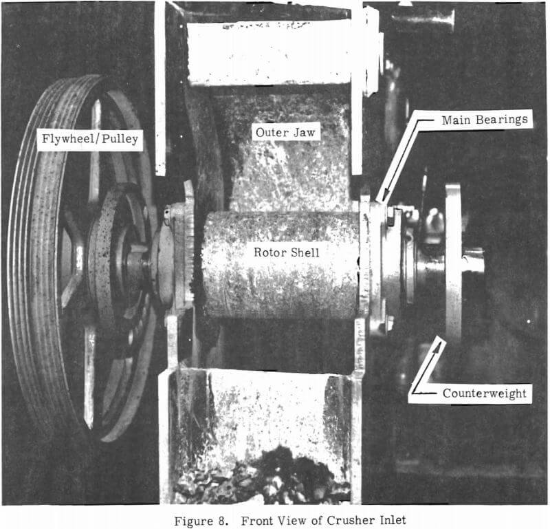
Figure 7 is a three-quarter view of the machine with the feed system removed. Although the full outer jaw profile remains hidden by the rugged side frames, the upper jaw pivot pin (which permits swinging the outer jaw to adjust discharge opening) may be seen along with the upper edge of the outer jaw. The cylindrical inner jaw or rotor shell is easily seen. The drive pulley (and flywheel) is visible on the opposite side of the machine while a counterbalance wheel is attached to the eccentric shaft in the foreground. Figure 8 shows all of these items and the outer jaw surface looking into the intake, again with the feed system removed. The simple, rugged geometry is clearly evident in this view.
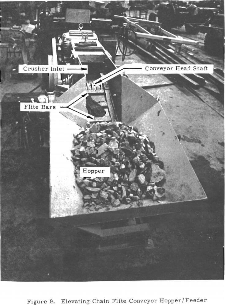
Figure 9 is a hopper-end view of the complete model system with the elevating chain conveyor system in place. A load of scale feed is visible in the hopper.
Figure 10 is a closeup of the conveyor headshaft, taken with the crusher removed. The spaced apart elements of the cogs are clearly visible as is the double chain drive system. Note also that the conveyor chain is covered by a protective shield. Figure 11 is a top view of the assembled chain conveyor and crusher with the ring bar grizzly in place. Five separate rings are clearly visible. The chain conveyor deck is also visible, showing extensions or “combs” which reach between the cogs on the headshaft. The crusher inner jaw or rotor shell is visible above the rings.
Scale Model Performance
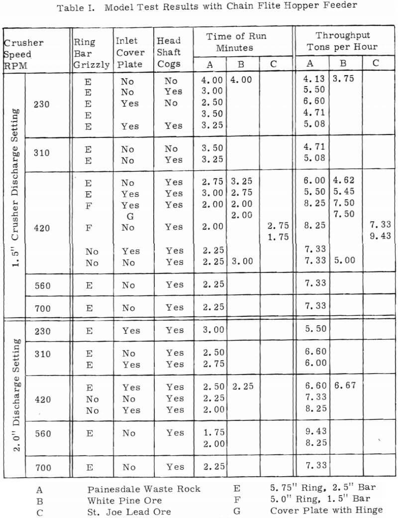
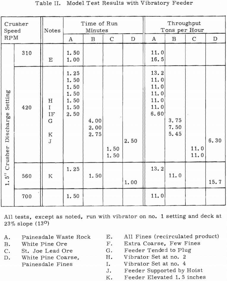
Scale model performance is summarized in Table I for the chain conveyor tests and Table II for the vibratory feeder. Three rock types were tested. Most tests were on “Painesdale rock” which was a mixture of Amygdaloid basalt having a compressive strength of about 24, 000 psi and epydote basalt averaging 18, 000 psi but ranging from 12,000 to 32,000 psi.
Run of mine ore from the White Pine Copper Mine, Containing sandstone having compressive strengths up to 35, 000 psi and shale at 18, 000 psi, was also tested in quantity. Two tests were done on a small sample of St. Joe Missouri lead ore which consisted of “5 zone” dolomite having a compressive strength of about 17, 000 psi, and “7 zone” dolomite at 26, 000 psi.
“Scale” rock consisted of 7 inch and smaller material. Since no relavent data were available to establish the proper size distribution of the “scaled” crusher feed, no elaborate screening procedures were used to produce that feed. Raw feed, with obvious oversize hand culled, was taken from the waste rock piles at the old Champion Mine at Painesdale, or from the main belt conveyor at the White Pine Copper Mine in White Pine, Michigan. In order to simulate typical run of mine muck, approximately equal quantities of crusher discharge and raw feed were mixed and fed to the crusher. This recipe produces a feed nominally containing 50 percent undersize material, which is the ratio found at the White Pine Mine, the proposed Phase III test site. In actuality, that half of the recipe comprised of uncrushed material tended to be very coarse (in quarter scale) so the effective proportion of undersize was probably somewhat less than 50 percent. It is felt, based on previous surveys and discussions with operators, that the undersize fraction varies between 30-50 percent at most mines. But there are gross exceptions, and the value depends not only on mining methods but on crusher size, conveyor capacity and other parameters.
The tables are largely self-explanatory. It is to be noted that of the two ring bar grizzlies tried, the “B” model was significantly better. It is believed that this combination allowed greater random motion of the rings to enhance both grizzly action and feed to the crusher. An “optimum” speed is evident at about 420 rpm.
For some tests an inlet cover plate was used, extending forward of the crusher over the incoming feed, apparently with little effect on the throughput. This plate was used to contain a “boiling up” of feed that occurred as a result of excessive conveyor speed, and it is not evident that the device is useful.
The vibratory conveyor clearly provided the higher throughputs due, perhaps, to several factors. The feeder was pitched downward, which undoubtedly helped, but it was felt that thorough “fluidization” of the feed, caused by the constant action of the feeder and the rotor, was the primary cause of increased throughput. There was also little “dead zone” in the crusher inlet, because the feeder pan (actually the grizzly section) was brought in close to the crusher rotor. Out of curiosity an attempt was made to use the ring bar grizzly with the vibratory feeder. The dead zone represented by the ring bar proved to be insurmountable due to the limited force-feeding capability of the vibratory type of feeder.
Further tests would be required to fully understand these data and to definitively compare chain and vibratory feed systems. There is no reason to believe that either geometry tested is in any sense “optimum”, but inasmuch as satisfactory throughputs have been demonstrated it is not of critical importance to further pursue this behavior with the model.
All data in Tables I and II are for total throughput, including that “free” material which passes through the grizzly. The “free” material represented roughly half of the throughput in all cases.
Conclusion of Model Tests
It is concluded from these tests that the rotary jaw crusher does provide adequate throughput in combination with either elevating chain or vibratory feed systems. To quantify this statement it is first necessary to scale up the model test data.
One’s first thought on scaling might be that throughput should scale with the square of linear dimensions for geometrically similar devices. Thus full scale throughput would be 16 times that of our quarter scale model. This would be true if throughput were proportional to flow area, but there is clear empirical evidence that this is not the case. Obviously there is considerable drag or resistance to flow associated with the rubbing of rock upon the crushing chamber surfaces. For a given flow cross section the relative significance of drag to throughflow is expected to vary as the ratio of circumference to area: that is, drag decreases relative to throughflow as size increases in something like the ratio of one over length. Thus larger crushers should display more than the length-squared increase in throughput.
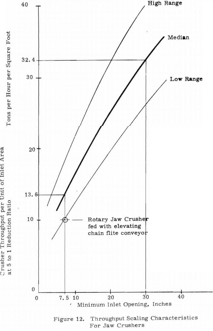
Figure 12 is a plot of actual crusher performance data as quoted by many manufacturers. While it is possible that such data are either conservative or inflated, a sufficient quantity of data was employed to insure that the slope of the curves, which is of primary concern here, is representative.
Data are plotted against minimum inlet opening since that is the critical parameter in machine selection. For a valid comparison, all data are for a total size reduction of 5:1, which corresponds to our design point (30/6 in full scale or 7. 5/1. 5 for the model). High and low manufacturer data are represented by the corresponding curves, with a mean curve interposed for our use.
Throughput per unit of inlet area is plotted – hence simple dimension-squared scaling, or constant throughput per unit area, would plot as a horizontal line. Clearly, the empirical curve differs significantly from that relationship. In fact, as shown, in scaling from a 7. 5 inch machine (our model) to a 30 inch machine (the full scale design), a gain of 32, 4/ 13. 6 or 2. 38 in throughput per unit area can be expected. The full factor for such a 4:1 scale-up is then 16 x 2. 38 or 38.
Using this scaling factor, Table III was prepared. It presents the expected performance of a full scale (30 x 48) rotary jaw crusher, based on model tests selected from the best combination of test model design variables for each rock tested, all with the elevating chain conveyor feed system.

Like the scale model, the predicted full scale performance represents total throughput. These predicted performances are clearly adequate in view of the Applications Study conclusion which recommended: “Throughput should be 100-300 total tons per hour in most cases. ” Also, test data to date indicate that a vibratory feeder will provide significantly more throughput than will a chain conveyor feeder. In view of the fact that neither feed system (nor the crushing chamber design, for that matter) is known to be optimized, it is clear that the rotary jaw crusher is entirely adequate for the intended application.
The performance of the scale model is also plotted directly on Figure 12. As with the commercial jaw crusher data, only the crusher throughput is counted (the grizzlyed fraction is omitted). It is evident that the scale model performance is quite respectable for the first try of perhaps the first new hardrock crusher geometry in many, many years.
Aside from the all important verification of throughput, the model tests disclosed additional features of importance in prototype design and application.
The expected smooth-running behavior of the fully balanced rotary design was clearly evident. This is a significant benefit in comparison to inherantly unbalanced oscillating jaw crushers, particularly with regard to frame and foundation requirements in a portable application.
The remarkable non-choking performance, including long term running (15 minutes) without damage with a blocked discharge, leads to two conclusions. First, the outer jaw redesign suggested in Section 2. 2 is clearly indicated as a means to achieve even better throughput. Second, the absence of overloads from ordinary choking behavior will allow a very much simplified release mechanism for occasional tramp iron injestion.
Prototype Design
Figure 13 depicts a common system configuration for low headroom sites used in conjunction with LHD-type haulage vehicles. The hopper-feeder shown is the elevating chain-flite conveyor type, with hopper dimensions capable of accepting an LHD having at least a 5 cubic yard bucket capacity. The crusher is set on a separate fabricated steel base containing the tail section of the discharge system, which in this case is a rubber belt conveyor. For ease of installation and maintainence (cleanup) this discharge belt is shown as a roof-hung rope-supported type.
A number of variations of this system configuration are possible, as previously described in Section Two. It is appropriate, then, to present each major component separately (crusher, feeder, and discharge system) in its full size, and then to describe the operation and performance of each in an integrated system.
Basic Rotary Jaw Crusher
Figure 14 (Dwg. E17112034) is a layout of the basic Rotary Jaw Crusher showing all major components including the ring bar grizzly. If a vibratory feeder is used, the ring bar grizzly is simply eliminated. Full physical specifications are given in Table IV, and certain features or key elements are described in further detail in the following subsection.
Structural
The frame is a box weldment (ribbed ans skinned) of mild steel, with an integral outer jaw of similar construction. At the rear of the machine is an additional weldment serving to house and protect the drive, and to provide rugged extremities for tramming. Frame dimensions are 12′ – 4″ long,
8′ – 0″ wide, and 6′ – 3″ high. Stripped frame weight is 12. 5 tons.
The frame can be built in four pieces (for small-shaft mines) comprised of two side frames bolted through a double-mortised jaw, and a ”back end” weldment field-welded during erection.
Rotor Assembly
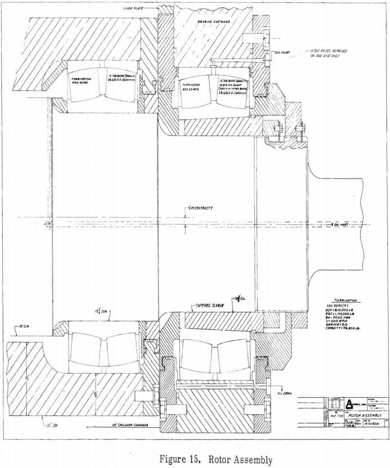
Figure 15 (Dwg. 17 112 031) shows one end of the rotor assembly. Double row spherical roller bearings are used, with oil lubrication. The entire assembly is self contained and can, by removing two retainer plates, be removed through the side of the machine as a unit without disturbing bearings or seals. Rotor eccentricity is one half inch (one inch throw. The eccentric shaft, which is 18 inches in diameter, will be machined from a heat treated low alloy steel forging, and the 30 inch diameter by 48 inch long shell will be cast manganese steel. The complete assembly, less flywheels, weighs about 9 tons.
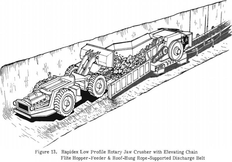
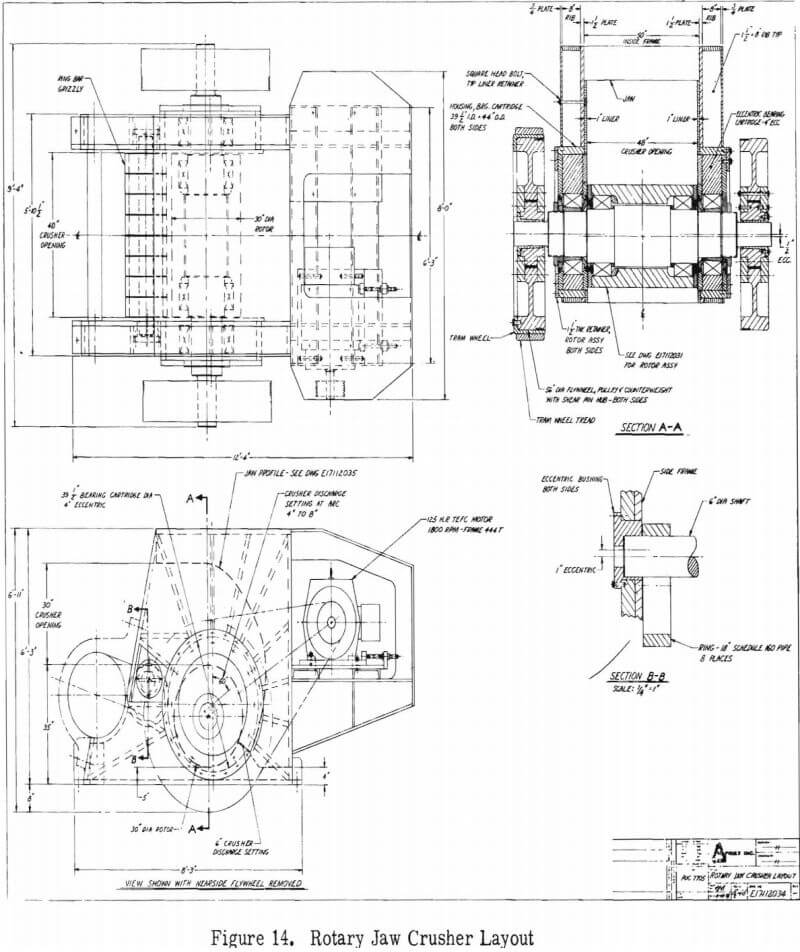
Table IV Rotary Jaw Crusher Specifications
Basic Size
30 x 48 inch inlet opening, 30 inch diameter rotor, 400 rpm
Type
Rapidex Rotary Jaw; horizontal rotor with one-half inch eccentricity (one-inch throw) and a free-turning rotor shell; horizontal inlet, modified log spiral crushing chamber with fixed outer jaw. Rapidex ring bar grizzly included for use with chain-flite hopper-feeder
Capacity
Estimated 200 tons per hour on coarse grizzlyed feed, 250 tons per hour (minimum) on graded grizzlyed feed, both at 6 inch discharge setting. Setting adjustable from 4-8 inches via eccentric rotor assembly motion
Structure
Mild steel box structure, ribbed and skinned plate. 1. 5 inch plate side frames, 1. 5 inch plate ribs, .75 inch outer skin. Trunion seat for chain-flite hopper feeder. Integral outer jaw also of box construction.
Dimensions
Height – 6′ – 3″ frame, plus 10 inch road clearance for tramming 7′ – 1″ total)
Length – 12′ – 4″
Width – 8′ – 0″ frame, 9′ – 4″ at rotor shaft
Weight
Total – 63, 000 pounds tramming weight
One piece frame, stripped – 25, 000 pounds
Rotor assembly (complete) – 18, 000 pounds
Flywheels – 5000 pounds each (2)
Assembly Rotor
Removable through the side frame as a unit with all bearings and seals intact
Eccentric – 18 inch diameter forged alloy steel, 15.75 inch diameter at shell bearings, 13. 375 inch diameter at main bearings
Bearings – double row Torrington spherical roller bearings; 15. 75 inch diameter; 1.145 million pound basic static capacity (each); load rating 96, 200 pounds (each) at 400 rpm, 5000 B10 hours, service factor 2.0
Lubrication – positive once-through oil for the rotor shell, positive recirculated and filtered oil for the main bearings
Seals – Axial half-labyrinth with radial labyrinth slingers on the dirt side. Radial labyrinth knife-edge flinger on the oil side in the rotor shell
Drive System
Single stage multiple V-belt; 125 HP, 1800 rpm TEFC motor; slide base take-up; final speed 400 – 500 rpm; motor removable through the top, rear, or either side; drive interchangeable from side to side
Tramming Wheels
Bolt-on-the-flywheel rim-treads, or removable pneumatic tires;
Rotor shaft and main bearing serve as axle. Customer-supplied tow-bar or tongue
Tramp Iron Relief
Double-shear type shearpins in the flywheels; flywheels spin free, captivated on taper-lock-keyed hubs; pins removable for steerability when tramming on flywheel rim-treads
Jaw Liners
Rotor Shell – cast manganese steel, 30 inch diameter, 5 inch thick, 48 inch long; rebuildable by welding
Outer Jaw – cast manganese steel toe piece; six cast concaves. All are epoxy backed and held by recessed square-head bolts, spring loaded
Crusher Adjustment, Discharge Setting
The rotor main bearings (in the side frame) are housed in large cartridges having outside diameters that are eccentric to the rotor axis of rotation by four inches. By rotating these cartridges in the side frames, the centerline of the rotor is moved through an arc which varies the discharge setting over the range of 4-8 inches. The cartridge retainer plates positively hold the rotor assembly and maintain crusher setting.
Drive System
A single stage direct V-belt drive is used, powered by a 125 HP, 1800 rpm motor. The motor can be removed from the crusher through the top, rear, or from either side, and the motor and belt drive can also be mounted on either side to accommodate preferred operator location, rib clearance, etc. The rotor pulley diameter is 56 inches, and its speed is approximately 400 rpm. Two pulley/flywheels are used for balanced dynamics, since the flywheels also act as counterweights for the rotor eccentricity.
Tramp Iron Relief
The flywheels are held with shear pins on hubs which are taper-lock-keyed to the shaft. These hubs retain the flywheels, yet allow the flywheels to spin free if tramp iron causes the double-shear pins (between the hub and the flywheel) to break.
Ring Bar Grizzly
The ring bar arrangement is similar to that of the model, spanning from side frame to side frame at the crusher inlet. However, in the full size crusher the bar is held captive in eccentric brushings which allow for ring bar adjustment to compensate for changes in crusher setting. The bar is removable through the side frame, while the rings are removed through the crusher inlet.
Jaw Liners
The “inner” jaw, which is the rotor shell, is a rebuildable manganese steel cylinder. The outer jaw, shown in Figure 16 (Dwg. E17 112 035), is lined with six cast manganese steel concaves and one cast toe piece. All are held in place with spring-loaded, square-head, recessed bolts, which is conventional practice for milti-piece jaw liners. The concaves, which are all identical, are backed and supported by epoxy filler of the type used behind cone and gyratory crusher concaves. The last, or uppermost concave is further seated by a final key-wedge at
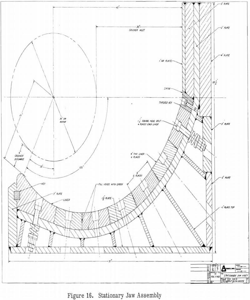
the top of the chamber. Bolted cheek plates inside the side frames complete the liner system.
Tramming
Two possible tramming systems are available, depending on mine road conditions and mine operator preference. The most portable arrangement involves bolting steel rims, lagged with a rubber tread, onto the flywheels and using the flywheels as tram wheels. The crusher rotor shaft becomes the axle, and the main bearings become the wheel bearings. Tramming height with this arrangement would be about 7″-2″, and road clearance would be 11 inches minimum. (Not shown is the custom tow bar or tongue needed to mate with the customer’s prime mover. )
If road conditions are too severe to use this “hard axle” approach, adequate suspension can be obtained by removing the flywheels and installing pneumatic tires in their place. A pair of truck or LHP tires, size about 18 x 25, 28 ply, would not only carry the crusher weight, which is 25 tons without the flywheels, but also protect the main bearings from hard bumps and provide about ten inches of road clearance.
Bearings and Seals
Double row spherical roller bearings are presently planned, with identical bearings in the rotor shell and in the side frames. These bearings (shown previously in Figure 15 ) have a much higher load capacity than is normally found in a 42 x 48 inch jaw crusher having a considerably smaller and more limber eccentric shaft. They also have more load capacity than most 48 x 60 inch jaw crushers. Bearing ratings are as follows for each bearing:
Speed – 400 rpm
Life – 5000 B10 hours
Service Factor – 2. 0
Basic Static Capacity – 1. 145 million pounds
Load Rating – 96, 200 pounds
Seals are of the axial half-labyrinth type, which seal and flush away dirt by continuous, slow leakage. Main bearing seals are further protected against outside dirt by radial labyrinth slingers, as are the rotor shell seals. In addition, the rotor shell seal is protected against internal oil sloshing by a radial labyrinth with a knife-edge flinger.
Lubrication
At high speeds with such large bearings, oil lubrication is required. The main bearings are lubricated by a positive oil flow of about one gpm each. This is standard practice, with the oil being re-circulated and filtered. Rotor shell bearings are tentatively lubricated by a positive once-through flow of clean oil, which leaks out the seals. Oil is introduced into the rotor shell through the eccentric shaft via a rotary union.
An alternate oil lubrication system, that is still under investigation for possible additional advantages, is oil mist. Oil mist might be cheaper because the same once-through type flow could be used for the main and the shell bearings. Its biggest potential advantage, however, lies in the possibility that the pressurized bearing areas and the resulting one-way flow of air/oil mist out through the seals could greatly improve seal performance.
Safety Features
The primary safety feature required by the rotary jaw crusher is the shear-type tramp iron relief built into the flywheels. In addition, and not shown for purposes of clarity in the machine drawings, suitable belt, pulley, and flywheel guards would be installed. Other safety features are inherent with the rotary jaw as designed, including; optional placement of the motor and drive (away from the operator); fully balanced dynamics; very low noise and dust levels; non-choking behaviour; good slab-breaking characteristics. Typical safety features usually specified or supplied by the customer include: motor overload protection; sequential interlocks between the crusher feeder, discharge conveyor, and main belt haulage; safety interlock between the bearing lubrication system (temperature, and pressure or flow) and the crusher start/run controls.
Electrical Controls
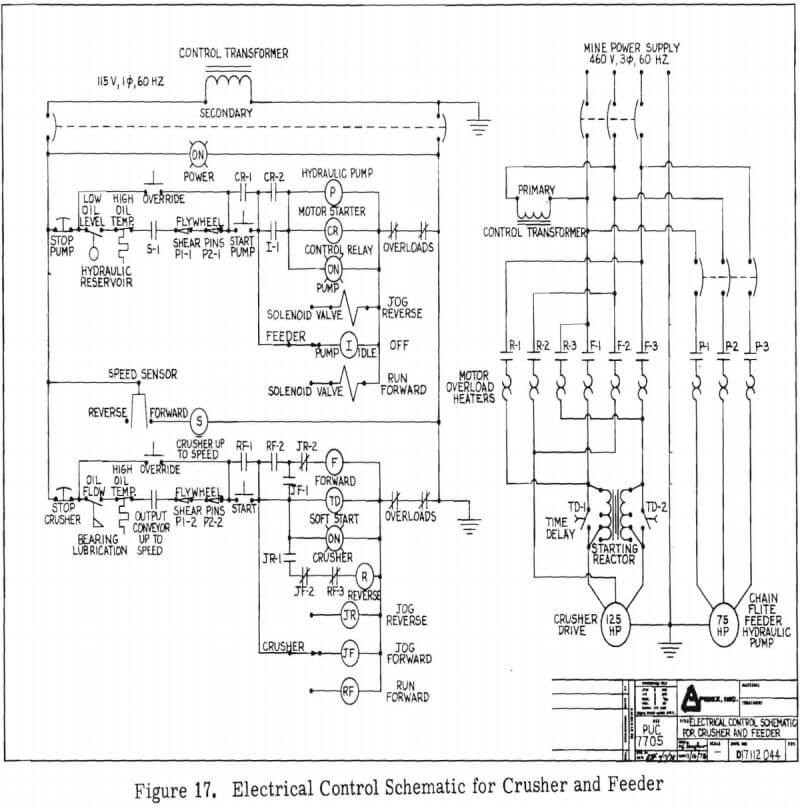
Figure 17 is an electrical control schematic for the crusher, including (in this case) the chain flite type hopper feeder. Controls and safety interlocks for the lube system are also shown, but a separate electrical schematic is not included.
Crusher Feeder Systems
Two feed systems are compatible with the Rapidex rotary jaw crusher. They are: chain flite conveyors, when used with the Rapidex ring bar grizzly; and vibratory feeders, with or without grizzly sections. Each type exhibits advantages for different mining conditions and site geometries.
Elevating Chain Flite Conveyor
Figure 18 (Dwg. R17 112 033 ) shows the design of a 30 ton hopper feeder employing an elevating chain flite conveyor. This is the recommended feed system for low profile operation, or for haulage vehicles having essentially floor-level dumping characteristics (i. e., trucks). The hopper-feeder is similar in construction to the successful heavy duty Stamler feeder breaker and it incorporates many proven Stamler components. Complete specifications are shown in Table V, with major features described in the following paragraphs.
The headshaft assembly of the hopper/feeder can be removed intact, like the crusher rotor, through the side frame. The side frame, in turn, is trunnion shaped and rests on a mating surface at the front edge of the crusher frame, held there by a pillow-block-shaped cap. This allows the feeder/crusher to accommodate grade variations between crusher sites without disturbing the desired relationship between the headshaft and the ring bar grizzly. It also allows the conveyor to be lifted on site (pivoted at the trunnion) in case the underside should need free access for unusual service. The input end of the hopper-feeder rests on the floor or on a customer specified footing perhaps like the one shown. Incoming haulage vehicles drive on a muck-fill ramp, two feet or less in depth, which levels the approach floor and allows the vehicles to drive well inside the hopper for clean dumping. Vehicle wheels will straddle the central chain conveyor,which is contained in a strong structural steel frame capable of sustaining the loaded vehicle weight.
A removable cover section in the hopper floor allows top-side access to the complete tailshaft and hydraulic take-up assembly, and the return (under) side of the chain conveyor is completely sealed by removable chain covers which contain carryback and cause it to be re-circulated. This arrangement, which is used in conjunction with toothless tail “sprockets”, has been proven by Stamler to be an effective method for reducing or eliminating under-machine cleanout requirements.
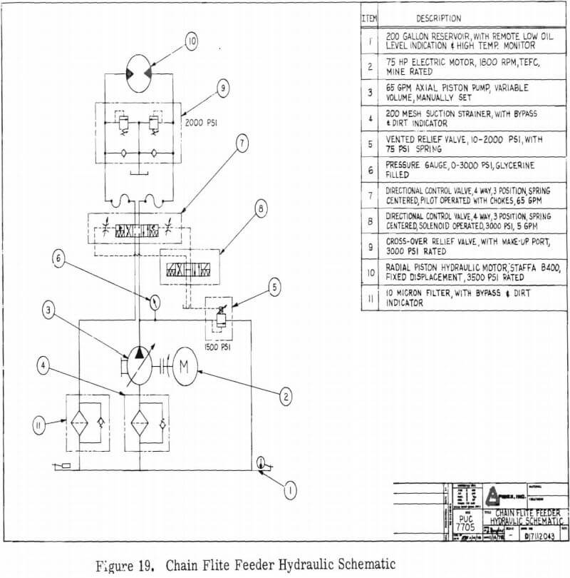
The hopper is 26′-6″ long, 13′-6″ wide, and 4′-4″ high, plus customer-specified tram wheels. Hopper side extensions, also customer specified, bring the useable hopper surge capacity to about 30 tons. The conveyor drive is hydraulic (75 HP power supply) for speed and stall control, with one stage of chain reduction (4:1 ratio) driving the Stamler chain and flites at about 45 feet per minute (10 rpm). Figure 19 shows the hydraulic schematic for the chain flite conveyor. Speed control is accomplished by using a variable displacement pump, manually set by the operator to match operating requirements and rock properties. Primary variables include throughput, size distribution in the feed, and strength and shape of the rock. Safety features include, in addition to the customary guards, hydraulic pressure relief at stall conditions and intermittent reversal capability to clear jams.
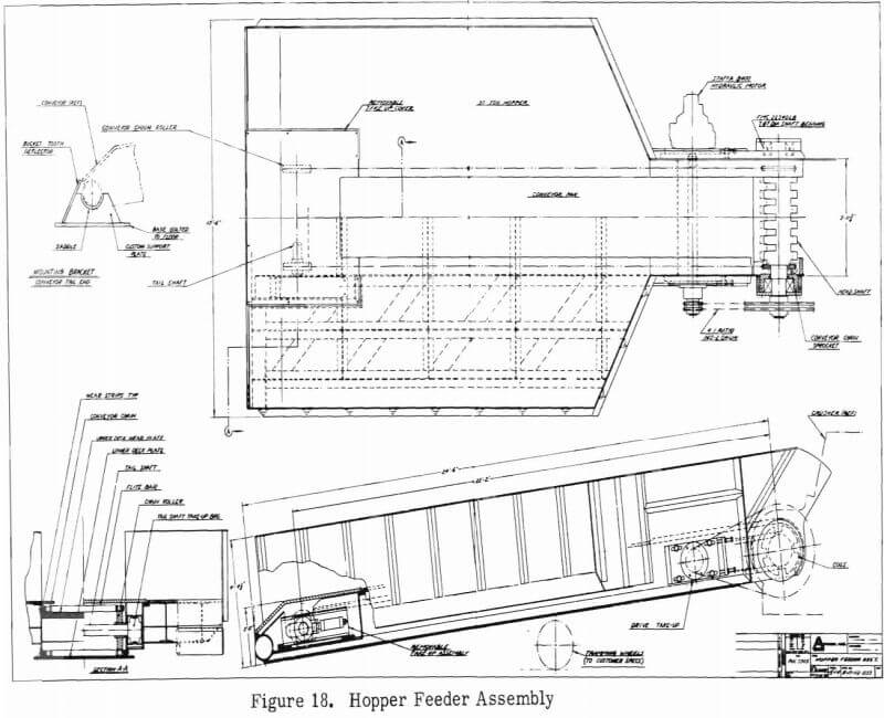
Table V
Elevating Chain Flite Hopper-Feeder Specifications
Type
Chain flite conveyor, trunnion mounted, at the crusher; rests on the floor at the intake end or on customer specified saddle-bumpers.
Capacity
30 ton capacity hopper, 400 ton per hour throughput
Dimensions
13′ – 6″ overall width
11′ – 10″ inside width
27′ overall length
4′ – 4″ high, plus road clearance and hopper side extensions
2′ – 0″ high hopper floor at intake end
Weight
50, 000 pounds, plus tram wheels and power supply
Conveyor
W. R. Stamler Corp., feeder-breaker chain and flite bars
Width – 40 inches centerline to centerline
Chain – alternating 3 and 4 inch pitch, 170, 000 lb. ultimate per strand
Flites – 2. 5 x 4. 0 inch solid alloy steel, 14 or 28 inch spacing
Headshaft – 13. 5 inch diameter live shaft with 7. 875 inch sperical roller bearings, assembly removable as a unit, automatic grease lube
Tailshaft – 4. 437 inch diameter with 4. 437 inch sperical roller bearings removable as a unit. Access through top of deck, automatic grease lube
Take-up – automatic, by grease cylinder
Sprockets – 17.948 pitch diameter plate type; toothless tailshaft rollers
Speed – up to 45 fpm, (10 rpm)
Drive
Hydraulic Power Supply – 75 HP (electric), TEFC 1800 rpm motor, 65 gpm 2000 psi, variable volume (manually set) pump, 200 gallon reservoir
Hydraulic Motor – Staffa B400 ten cylinder radial piston motor, rated 225 HP, 3500 psi maximum, operating pressure 1500 psi relief setting
Final Drive – 4 to 1, 160-2 chain reduction, mechanical slide take-up
Structure
Wide flange beams, 16 inch x 45 lb., with pipe, channel and plate ribs and counters
Hopper – dead-type, one inch thick mild steel floor, half inch thick ribbed plate sides
Conveyor deck -1.5 inch mild steel with .75 inch Ultramet wear plate
The full size design is essentially a scale-up of the successful model, including the live headshaft with cogs, and the ring bar grizzly. The ring bar grizzly is comprised of inexpensive components that can be adjusted or replaced in the field by the operator in order to accomodate local conditions and rock properties. Rock shape, percent-of-fines, and desired product size are the main factors to be accommodated when adjusting the ring bar grizzly.
Vibratory Feeder
Almost any heavy-duty vibratory feeder can be used with the rotary jaw crusher provided, of course, normal design selection criteria are followed. Solid deck feeders, either sloped or level, and feeders with grizzly sections can be used. No ring bar grizzly is required.
Since the deck of the vibratory feeder must be level with (or above) the top of the crusher rotor, it is apparent that additional site headroom is required over and above that needed for the elevating chain flite feeder. If such headroom is available or cheaply obtainable and suitable vehicle ramps can be arranged, then the vibratory feeder offers significant advantages over the chain flite feeder. These advantages include lower initial and operating costs, particularly in abrasive applications, and, according to the model tests, improved throughput. Overall site geometries, including the impact of various discharge systems, are discussed in a following section.
Discharge Systems
Two acceptable discharge systems have been identified and designed. They are chain conveyors of the longwall type, and conventional rubber belt conveyors.
Chain Conveyor Discharge
Figure 14 presented in Section Three showed that the basic crusher was only 6 foot 3 inches tall. Substantial inches must be added to this height, however, to accommodate the free fall of crushed material, and the subsequent conveyance of that material away from the crusher. Figure 20 (Dwg. 17 112 041) (top view) shows the design of a crusher base having a built-in Westfalia Panzer Conveyor. This base and conveyor, which represents the lowest discharge system possible, adds about 21 inches to the installed height of the crusher and results in a total machine height of 8′ -0″. Chain type discharge conveyors are expensive to buy and expensive to operate, but they do permit very low profile operation by virtue of their compact geometry and their ability to operate “on” the floor with no underneath cleanout space.
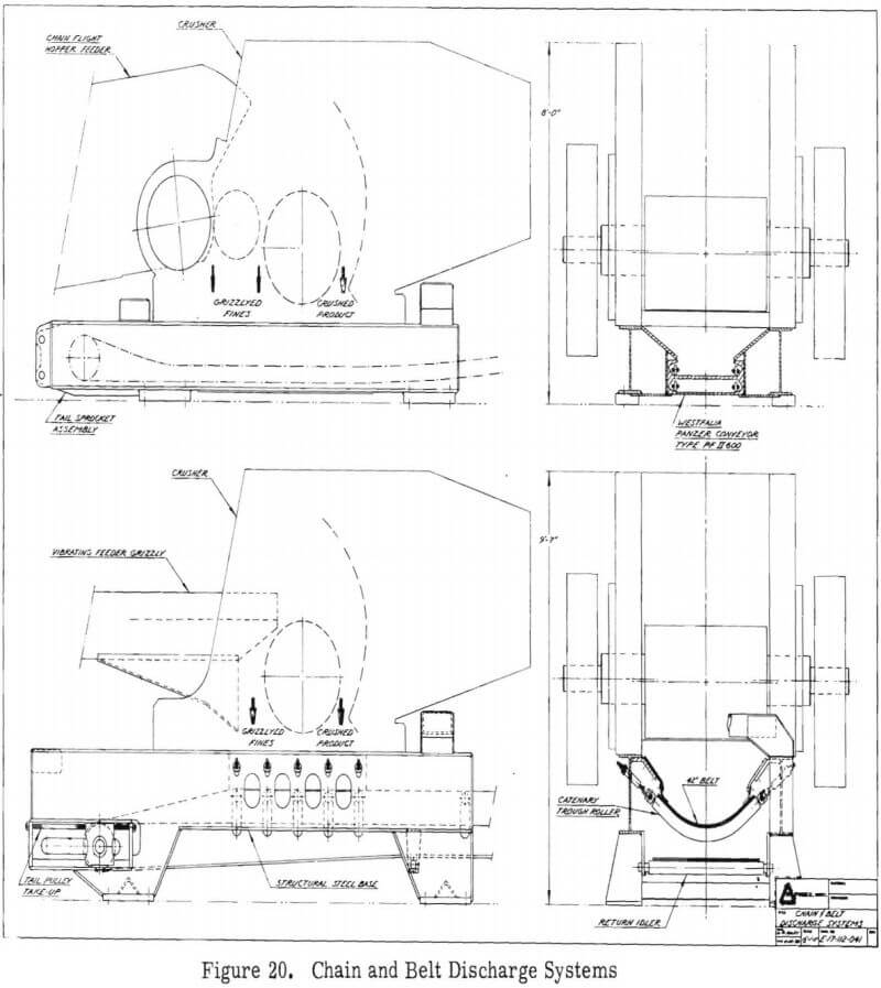
In addition to very high initial cost, which can exceed $2000 per foot for short conveyors, operating costs for a chain discharge conveyor of any significant length (40-80 ft) are likely to exceed the crushing costs on a per-ton basis. Consequently, this arrangement is likely to be economical only in non-abrasive applications where site headroom is unavailable or very expensive, and the conveyor can be very short. This would include primarily those situations where the crusher is to be moved very frequently, which would tend to result in a high site cost per ton due to the few tons over which excavation costs could be amortized. Speaking long term, non room and pillar mines would fit this condition.
Belt Conveyor Discharge
The lower views of Figure 20 show the belt conveyor discharge system, which is also built into a fabricated steel crusher base. Due to the relative fragility of the rubber belt conveyor, generous clearance is provided between the belt loading point and the crusher discharge. When underneath cleanout space is also added, the crusher base becomes 40 inches in height (or 19 inches higher than the chain conveyor base) and results in a total machine height of 9′-7″. In time and with full scale prototype experience, it may be possible to reduce this height by as much as 7 inches, but in the absense of such experience, conservative clearances are considered justifiable at this time.
Site Geometries
Various combinations of feeders and discharge systems can be arranged, depending on the site conditions, rock properties, and vehicle selection. The lowest profile arrangement utilized the 8 foot high chain discharge system and the elevating chain flite hopper feeder, as shown in Figure 21 (Dwg. D17 112 036). With 9 feet of headroom, this system will accept a 5½ cubic yard LHD with an ejector bucket (shown), smaller LHD’s with standard buckets, or small telecoping or ejector type trucks.
With 10½ feet of headroom the 9′-7″ high rubber belt discharge system can be used. This also allows more flexibility and efficiency in vehicle selection including, as shown in Figure 22 (Dwg. D17 112 037 ) the use of standard-bucket LHD’s up to 5½ cubic yard capacity. Figure 23 (Dwg. D17 112 038) shows that this same arrangement will accept an 18½ cubic yard telescoping truck.
The use of a vibratory feeder and a belt conveyor discharge results in a hopper “tailgate” height comparable to the sideboard height of an ejector-type truck. As shown in Figure 24 (Dwg. D17 112 039), this arrangement is a likely candidate for extremely abrasive applications and/or mines using LHD’s only. Sloping sites are also attractive for this geometry, since the slope can be utilized to reduce the dump point height and, therefore, the headroom required.
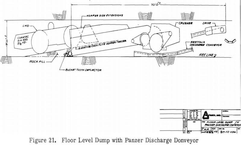
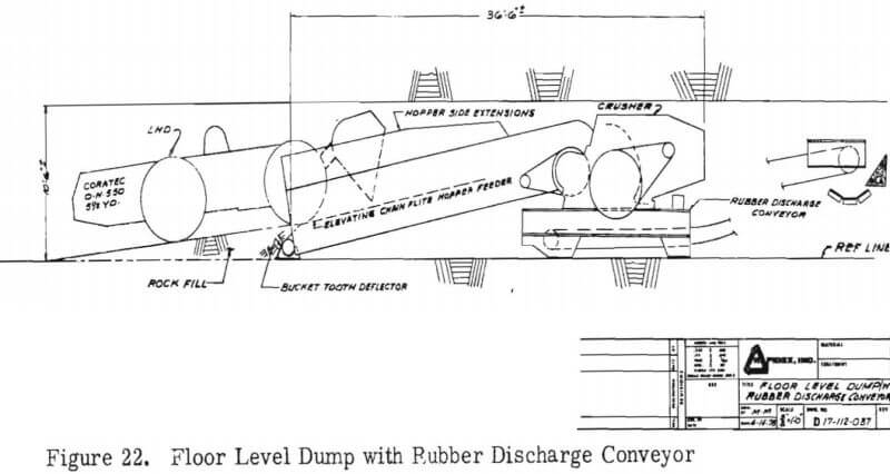
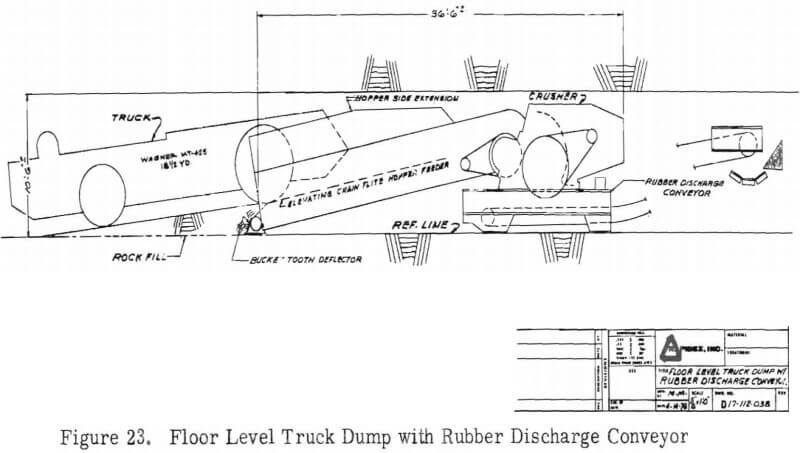
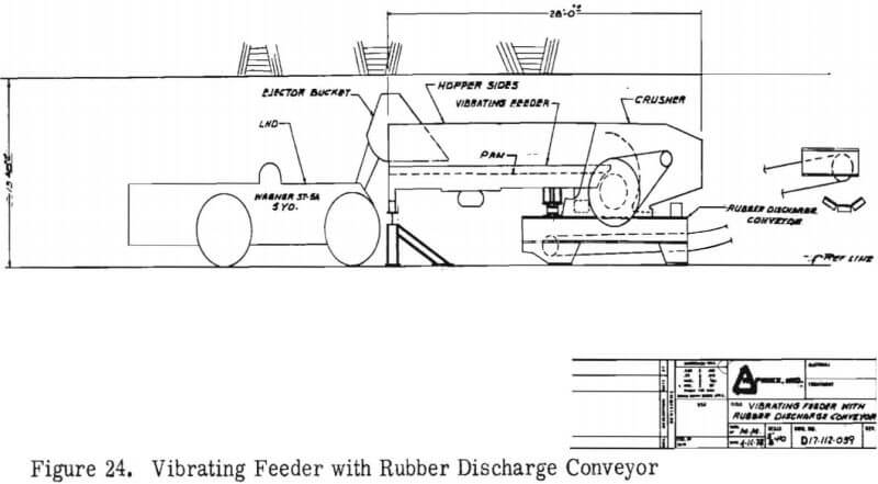
With 13 feet of headroom and a level site, this arrangement can be loaded by a 5 cubic yard LHD having an ejector bucket. Slightly more headroom would be needed to accommodate standard (5 yard) buckets. Fifteen feet of headroom and a muck ramp would be needed to accept the 18½ cubic yard truck shown previously.
Crusher Operation
The system is comprised of three major components, namely the hopper-feeder, crusher, and base-discharge system. Each piece is moved and set up separately.
Crusher Move-Up Sequence
Using the arrangement of Figure 23 as an example (chain flite hopper-feeder and belt conveyor discharge) the move-up sequence is approximately as follows:
- Preparations for the move will be made during normal operation, so that non-productive time is minimized.
- If main haulage is by belt conveyor, that line would be extended (or prepared for extension) during routine operation.
- A spare crusher base, and possibly a spare discharge conveyor drive, would be installed on the new site prior to the move-up. Hopper-feeder floor mounts are also installed, as are all utilities and any required site preparation or excavation.
- On shutdown, the hopper feeder is disconnected and towed to a holding site.
- Crusher tram wheels are installed, the crusher is unbolted from its base, and then towed to the new site. Portable ramps are used to lift the crusher slightly clear of its base as it is towed off the base.
- The portable ramps are used in reverse sequence when rolling the crusher onto the new site. Tram wheels are removed.
- The discharge conveyor, if not already installed, is then hung, threaded, and trained. This may include move-up from the earlier site if a spare belt and rope suspension components are not available.
- The hopper-feeder is rolled into position, bolted to the crusher, and (probably) bolted to the floor mounts.
- Utilities are connected, and after the muck fill ramp is in place the system is ready for operation.
- Spare components at the old site are recovered, serviced if necessary, and made ready for the next move.
Routine Operation
Until experience has been gained which would allow for the design of highly reliable automatic controls, it is expected that the crusher will be operated full time by one person. Mucking crews will tram to the crusher, dump, and return to the production site. The crusher operator will be primarily concerned with routine on-line maintenance, under-belt cleanup, data gathering and, of course, clearing jams and collecting tramp iron. Major spillage in and around the intake end of the hopper would likely be handled by the LHD operators.
Special Equipment
The most significant piece of required special equipment is the prime mover needed to tow the hopper-feeder and the crusher. In most mines this would be a retired and specially converted loader or LHD, but the job could also be handled by a production piece of equipment using a specially made tow bar, tongue, or adapter. For major servicing, a small mobile crane or a utility sized LHD or loader would suffice to lift and handle virtually any component, including flywheels or tram wheels.
The one major exception is the rotor assembly, which weighs 9 tons. If it is necessary to change the rotor assembly on site, rather than in an underground or surface maintainence shop, a special crane rail could be installed onto the top of the crusher. Hoist trolleys on this rail would support the rotor as it is extracted through the side of the crusher frame. At 9 tons, the assembly could then be handled by a 5½ or 8 yard LHD or loader, and with the rotor assembly removed, new jaw liners can be installed on site.
Performance Specifications
In addition to the many physical specifications already presented, the rotary jaw crusher is expected to perform to the following specifications:
Feed Size
- 30 x 48 opening; able to handle any chunk that will fit, including slabs of any length.
Product
- Nominal minus 6 inches
- Adjustable 4-8 inches
- Very uniform product
- Corrugated or ribbed jaw shapes available
- Any rock type acceptable
Throughput
- 180-240 tons per hour; crusher only, on graded feed, depending on type of rock and feeder
- 380 – 400 tons per hour total when 50% of the feed is grizzlyed undersize.
Intake
- Dead type hopper, nominal 30 ton capacity (any size possible)
- Elevating chain flite hopper-feeder for lowest profile and floor level dump geometry.
- Vibratory feeder for very abrasive applications and/or higher headroom sites.
Discharge
- Chain type longwall conveyor for lowest profile
- Belt conveyor for lowest cost, most portable system
Horsepower
- Crusher – 125 HP 1800 rpm electric
- Chain flite hopper feeder – 75 HP electric/hydraulic power supply
- Vibratory feeder – 30 HP electric
- Belt conveyor discharge – approximately 20 HP electric, depending on grade change
- Chain conveyor discharge – 75 HP electric (70 feet long)
Move Requirements
- One or two shifts downtime
- Approximately 6 man crew for move, depending on mine conditions.
Approximate Prices
- Crusher – $155,000 complete with drive
- Chain flite hopper-feeder- $145,000 complete
- Crusher base – $10,000
- Chain discharge conveyor – $2000 per foot
- Belt discharge conveyor – $14,000 with drive
Estimated Operating Costs
- Crusher – $.04 – $.08 per ton, depending on rock properties and abrasivity
- Chain flite hopper-feeder $.08 – $.20 per ton, depending on rock properties and abrasivity
- Chain discharge conveyor – $.05 – $.50 per ton
- Belt discharge conveyor – $.02 – $.05 per ton
- Site costs (move-up) – highly specialized and variable, $.03 – $.08 per ton
Commercial Components
Rotary Jaw Crusher and Chain Flite Hopper-Feeder
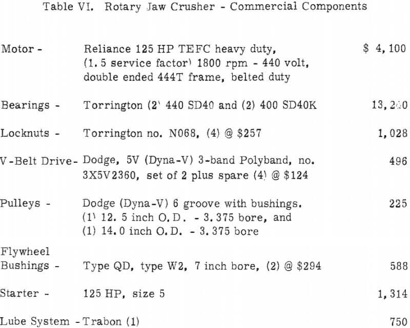
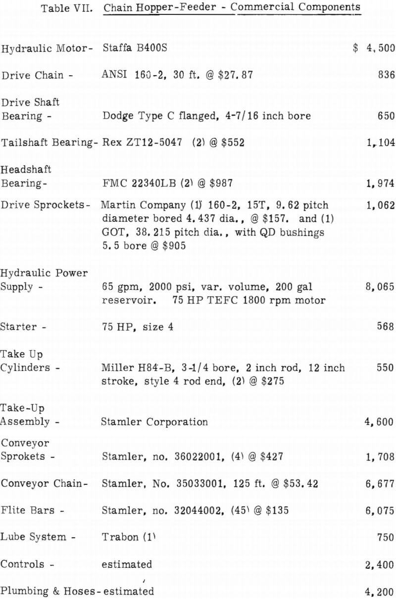
Tables VI and VII present a listing of the major commercial components contained in the crusher and in the elevating chain flite hopper-feeder, respectively. In some cases equivalent components are available from alternate manufacturers at comparable prices.
Vibratory Hopper Feeder
The only significant commercial item in this feed system is the vibratory feeder itself, and there are many acceptable choices depending on the application. A representative choice would be:
Hewitt-Robins extra heavy duty Eliptex vibratory feeder with straight or sloped grizzly. Vibrator model VL-11 in a 46 inch wide by 20 foot long feeder. Approximate cost is $42,000 including a 30 HP drive.
Chain Discharge Conveyor
Based on an estimated 60 feet of length required to load the grizzlyed undersize, clear the crusher discharge, and elevate the material for transfer to a main belt, the following conveyor is selected:
Wesfalia Panzer Conveyor Type PF IV 600; complete with chain tensioner, 8 pan sections, 75 HP drive section, tail section, spill boards, delivery bridge, and adjusting tools. Approximate price $160, 000.
It should be noted that the selection of a chain discharge system and, therefore, its cost, will vary considerably between different applications. This selection is considered to be the upper limit both in design and cost, and factors such as site layout and rock properties (abrasivity can have a significant effect on the selection process.
Belt Discharge Conveyor
This system,excluding the fabricated steel crusher base, costs about $15,000 and is comprised of numerous small components such as impact idlers, troughing idlers, return idlers, rope, chain, brackets, turnbuckles, pulleys, pulley take-up, 30 HP motor, gearbox, and belt. There are many alternate sources for each component, and many individual preferences for type and style, but the cost stated is representative for a 30 HP, 36 inch wide, 100 foot long, rope supported, chain hung system.
Updated Applicability Assessment
The Applications Study, which preceded the current design effort reported herein, analyzed in detail the various mining applications in which portable underground crushers might be put to economic use. From that study came the Rapidex rotary jaw concept and the system specifications on which the present model and full size prototype design are based. As the design took shape and definition during this phase, those specifications were re-examined for possible update to ensure that they were realistic and appropriate in light of their effect on:
- The design & cost of the equipment
- Operating costs of the overall system
- The market needs and demands
- Variations in installation and operational procedures from mine to mine
Based on that update the following points can be reported:
System Specifications
None of the basic system specifications, which were summarized in Section One, need be changed or substantially modified. The major impact of the update was a reemphasis of the fact that the specification, though valid, should not be interpreted too narrowly or too rigidly. Simplicity throughout, and versatility, particularly where feed and discharge systems must interface with existing constraints, became the underlying theme.
Installed machine height requirements appeared to be the most flexible specification from mine to mine, because each operation exhibited not only greatly different site geometries and vehicle types, but also (and more importantly) tremendously variable costs associated with the creation of additional site headroom. However, nearly all operators reconfirmed the need for ease of portability and very low tramming height, as originally specified.
Performance Specifications
No basic changes were found needed, except that a few operators expressed a desire for a range of total throughput capability somewhat wider than the 100-300 tons per hour set originally. As designed (with grizzly scalping) the rotary jaw is expected to be capable of about 400 tons per hour and can, of course, be built in larger or smaller sizes with appropriate changes in external dimensions.
Equipment Cost
Originally estimated at $2 50, 000, the complete system, capable of up to 400 tons per hour and consisting of elevating chain flite hopper-feeder, crusher, base, and belt discharge conveyor, is now estimated at $300-325, 000. A vibratory feed system could, depending on site geometry, reduce this amount by $30-50, 000.
Operating Costs
These were stated in Section Three. The updated assessment did point out that relative values, and therefore design priorities, can vary widely from mine to mine. One operator may be burdened with high per-ton crusher move-up costs due to excavation requirements, roof conditions, or move frequency, while another may be more concerned with the reliability and operating costs of feeders and the like, due to abrasive conditions. The underlying versatility theme is again evident here. The Rapidex rotary jaw crusher, which is the heart of the low profile system, appears to offer a genuinely attractive operating cost picture which is in line with proven hardrock crushers, while at the same time allowing the selection of feed and discharge systems having attendant operating costs appropriate for the conditions at any particular mine.
Installation Procedures
Some mines will find it impossible to pass the crusher frame down their older (smaller) shafts in one piece. The rotary jaw crusher frame can be built in four pieces to accommodate those mines.
The Market
Conclusions of the Applications Study are still valid, namely a near-medium term underground market (10 years) of about 40-60 systems. Success in this segment (primarily room and pillar) will double or triple the market by virtue of expansion into other mining methods. The domestic surface market, though not analyzed, is felt to be significantly larger than the underground market.
Updated market analysis further served to emphasize the fact the mining industry demands reliable, proven equipment with performance and operating costs known to a relatively high level of certainty. A revolutionary new concept like the Rapidex rotary jaw crusher, however promising, cannot and will not fullfill this requirement until and unless Phases II & III are successfully completed. Existing manufacturers have shown an unwillingness to expend development funds on new concepts. They feel, and rightfully so, that development of an essentially new piece of equipment requires not only a substantial cash investment and a sizable risk, but takes so much time that the payback period, even with relatively quick market penetration, is excessive. Developments in the industry have tended, therefore, to be characterized by incremental “breakthroughs” providing, at best, only improvements to, or new versions of, existing hardware. For a revolutionary product like the portable underground crusher, this reluctance to expend development (not research) dollars is further compounded by the perceived size of the market; but given a product of proven performance (low risk) and of obvious profitability (short payback), equipment manufacturers are able to commit large investments in development, testing, and marketing.
The Bureau of Mines program at hand, beginning with the prior studies (1) (2) (3) and concluding (hopefully) with a successful Phase III, is expected to provide the missing ingredient needed to bridge a gap in the industry. That gap exists between industry demands for proven equipment on the one hand, and the manufacturer’s reluctance to risk development funds on new products without proven profitability on the other hand.
Phases II and III Program Plans
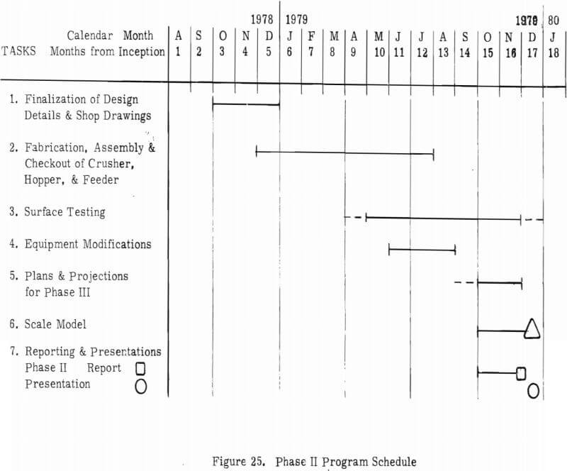
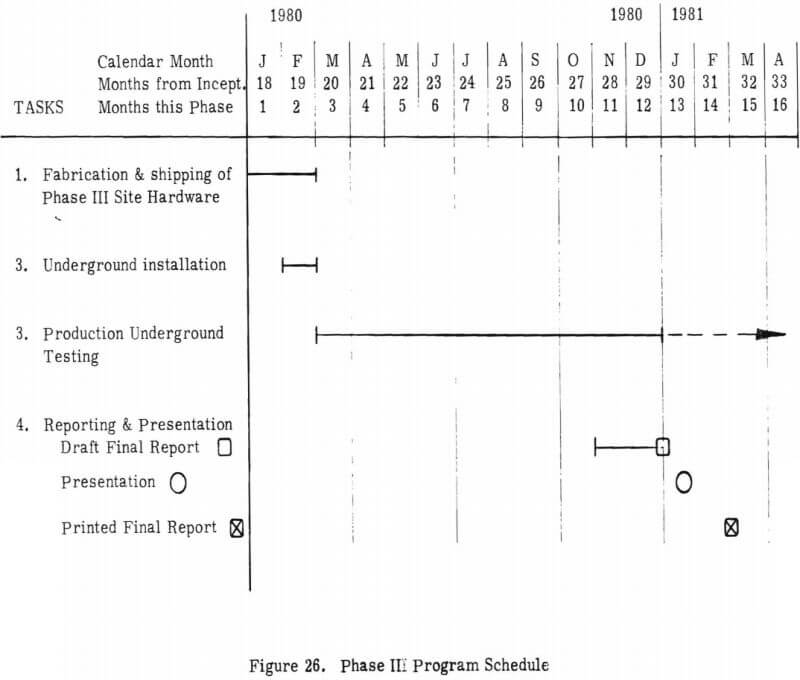
Plans call for the rotary jaw prototype to be built by Rapidex and Coratec at Painesdale, Michigan, and surface tested there in the summer of 1979. Phase II will be about 15 months long beginning in October of 1978, and ending in December, 1979. Figure 25 shows the distribution of tasks. The Phase III underground test, shown in Figure 26, will last a minimum of 12 months, occurring during calendar 1980 and the early part of 1981, and it will take place at the White Pine Copper Mine in White Pine, Michigan.
Phase II Construction and Surface Test
The elevating chain flite hopper-feeder design will not be built in Phase II. Due to the abrasive conditions at White Pine, it is expected that a feed system based on a vibratory feeder will provide significantly lower operating costs. The entire Phase III complement of equipment, including the crusher and a vibratory hopper feeder, will be built and surface tested in Phase II.
During Phase II, White Pine expects to provide the use of certain loading equipment, the vibratory feeder to be used in Phase III, and considerable engineering advice and assistance to insure that the entire system is fully surface-proven and ready for a legitimate underground production test. The White Pine commitment, presented in letter form in Appendix A, represents a willingness to expend significant resources in the belief that the rotary jaw crusher will, if properly engineered and tested in Phase II, be of immediate benefit. Phase II will, therefore, be a long term test. By crushing many thousands of tons of several rock types, it will seek to determine such things as wear rates of critical parts (operating costs), service requirements (maintenance costs), up-time (availability), and an estimate or projection of rebuild life.
Phase III, Underground Test
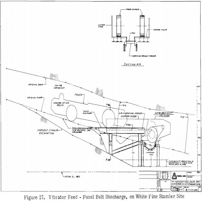
During Phase III, the underground production test, the rotary jaw crusher will be deployed in much the same manner as White Pine’s present Stamler feeder breakers. That is, an excavation and steel substructure will be employed to allow the crusher to sit atop a main belt conveyor, thus eliminating any discharge system entirely.
This can be accomplished in the same size excavation presently employed by feeder breakers as shown in Figure 27 (Dwg. D17 112 040), which is the anticipated site layout superimposed on an actual former Stamler site.
White Pine will operate the system in a production mode, performing all operating and maintenance functions, and Rapidex/Coratec will provide all spare parts and maintenance items unique to the rotary jaw system. Normal cost accounting procedures at White Pine will provide most of the needed operating data, but additional surveillance and monitoring will be performed, particularly during crusher move- ups, by White Pine Mine Research Staff, Coratec, and Rapidex. One or two move-ups, plus the initial installation, would normally occur in a 12-14 month production period.
Phase III Goals
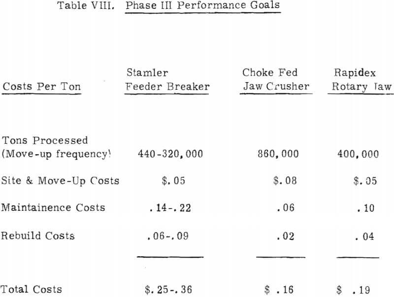
Feeder breakers and jaw crushers at White Pine currently exhibit operating costs dependent upon the relative proportion of shale and sandstone, as shown in Table VIII. Also shown are the target costs for the rotary jaw crusher.
Several points deserve explanation regarding Table VIII. First, the apparently high cost of the feeder breaker is partially offset by reduced haulage costs made possible by its more frequent move-up cycle and shorter haul distance. The table indicates that the rotary jaw is expected to achieve the portability and site costs (and haulage costs) of the feeder-breaker, while having operating maintenance and rebuild costs more in line with a hard rock jaw crusher. Maintenance and rebuild costs for the rotary jaw system total $.14 per ton, which includes the wear cost associated with the system’s vibratory hopper feeder. The choke fed jaw has no feeder, which accounts, in part, for its lower maintenance and rebuild cost of $.08 per ton. In actual use, the mine’s haulage vehicles serve as the “feeder”, slowly metering their load into the choke fed jaw.
Costs Not Included In the Totals:
- Operator costs.
- Equipment capitalization (replacement cost! is excluded, since major rebuild effectively replaces the equipment many times.
- The effect of reduced or increased haul distance on haulage cost is excluded.
