One objective of Project Gnome is to study the feasibility of a phase of the Plowshare program recovering thermal energy from an underground nuclear explosion. The test will be conducted in an underground salt deposit. It is anticipated that some of the energy thus released will be stored as thermal energy in molten salt. This report describes the pre-Gnome experiments conducted at the Federal Bureau of Mines Metallurgy Research Laboratory, Boulder City, Nev.
The objectives of this study were to determine the problems involved in the recovery of thermal energy from molten salts to assist in planning the experimental program for the Gnome project.
The heat-transfer characteristics of molten salts were determined and found to be effective in heating the contact gases to a satisfactory temperature for power generation. Water was more effective than air in the removal of heat from molten salt. The major problem was the salt entrainment of the effluent gases. The fine salt particles carried by the gas stream were deposited in the exhaust system and eventually plugged the pipes. The gases reacted slightly with the molten salt, which resulted in the effluent gases becoming slightly acidic. The materials used for construction must be designed to withstand the corrosive atmospheres caused by the possible chemical reactions involved.
The general objective of the Plowshare program of the Atomic Energy Commission (AEC), is to develop peaceful uses of nuclear explosives, such as in earth moving, mining and oil development, preparation of chemicals and isotopes, and power production. Project Gnome, one of the proposed Plowshare experiments, is designed in part to determine the feasibility of recovering power and isotopes, from a subsurface salt bed melted by the energy of a nuclear explosion.


The test for the nuclear explosive would be conducted in a subsurface salt bed near the 1,200-ft. level as indicated in figure 1. The energy liberated from the nuclear reaction should form a cavity with a pool of molten salt in the bottom. After detonation, it is planned to force air through the subsurface chamber and back to the surface by means of drill holes in order to collect the isotopes that will be formed. Figure 1 shows the general arrangement of the experiment. After passing the air through the chamber for the isotope study, either air or water will be circulated through the cavity to generate hot gases or steam by extracting the thermal energy from the molten salt. The amount of heat extracted and the properties of the effluent materials will be studied to determine the possibility of power generation from a source of this nature.
The Gnome experiment, which will be conducted in an isolated area of New Mexico (see figure 2), is not the same as geothermal power production. Steam and hot water from hot springs and fumaroles in volcanic areas are sources of natural power, whereas in the Gnome project the thermal energy will result from an underground nuclear explosion.
To conduct some pre-Gnome experiments was desirable to determine, if possible, the problems that would be involved in extracting heat from molten salts, the relative rate of extraction by various fluids, and the methods of adding the fluids to the cavity.
In the summer of 1959, the Lawrence Radiation Laboratory, Livermore, Calif., conducted a series of preliminary experiments. These experiments indicated that salt entrainment by the effluent gases was a major problem in plugging the pipes, and that some chemical reactions took place which also should be defined.
To establish the conditions for the Gnome experiment, it was determined that experimentation should be made on a larger scale and with better control of conditions than could be conducted at Livermore with the available services. Since the Bureau of Mines had equipment available and experience in working with molten salts, a contract was issued by the AEC to continue research in this field. Experimental studies at the Bureau of Mines Metallurgy Research Laboratory, Boulder City, Nev., were begun in October 1959. The work was performed on a cooperative basis with the Lawrence Radiation Laboratory.
Specific Experimental Objectives
In outlining the pre-Gnome experimental program the objectives were determined to be: (1) To determine the characteristics of heat transfer from the molten-salt surface to the thermodynamic fluid in contact with the molten salt. (2) To study the mechanism and rate of salt entrainment in the effluent gases. (3) To determine operational procedures that would minimize or eliminate the plugging of the exhaust pipes by salt entrained in the effluent gases. (4) To determine the chemical interactions between the molten salt and the heat-transport gases. (5) To determine the corrosive nature of the gases to materials of construction. The following procedures were established:
a. Pass air over and bubble air under the surface of molten salt at various flow rates.
b. Pass pregenerated steam over the salt as a comparison with air.
c. Generate steam at the salt surface by adding water to the system to determine the relative heat-extraction characteristics of water.
The first method of heat exchange would be applicable to a gas turbine cycle, whereas the last two modes, using water and steam as circulating fluids, are more important, because at Project Gnome the feasibility of operating with steam is being considered. Besides the effects of the different methods of adding the thermodynamic fluids to the system on the rate of heat extraction and salt entrainment, the chemical phenomena were determined by collecting and analyzing the effluent gases. Corrosion specimens were placed in the exhaust system to determine the corrosive effect of the hot fluids on various construction metals.
Experimental Equipment
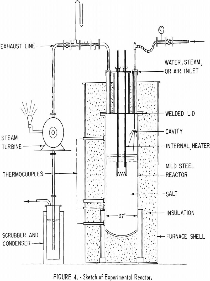
The experiments were conducted in two separate phases using the same equipment in general. The salt container used for these experiments consisted of a mild steel reactor which was 27 in, inside diameter and 72 in, deep. The vessel was insulated to maintain, as closely as possible, isothermal conditions throughout a single test. The heat was supplied to the system by passing an alternating current through the molten salt. Mild steel electrodes were immersed and positioned so that most of the IR drop was through the salt. The system was equipped with a thermocouple, also immersed in the molten salt, which controlled the alternating-current source and was used for temperature control. The lid was welded to the top and had ports provided for sampling, visual observation, thermocouples, for installation of air and water inlet equipment, a pressure-relief arrangement, and an effluent gas exhaust. Flowmeters, pressure devices, thermocouples, and a dewpoint gage were placed in the inlet system to regulate and measure the amount and temperature of the material that was passed through the system. Several thermocouples were positioned in the chamber and the exhaust lines to measure the temperature increase of the effluent gases. The temperatures were recorded on a Brown multipoint recorder, By knowing the mass of material, its thermal properties, and the temperature increase, the quantity of heat removed was calculated. Equipment was placed in the exhaust line to collect samples for analysis, and the effluent gases were finally passed through a water scrubber.
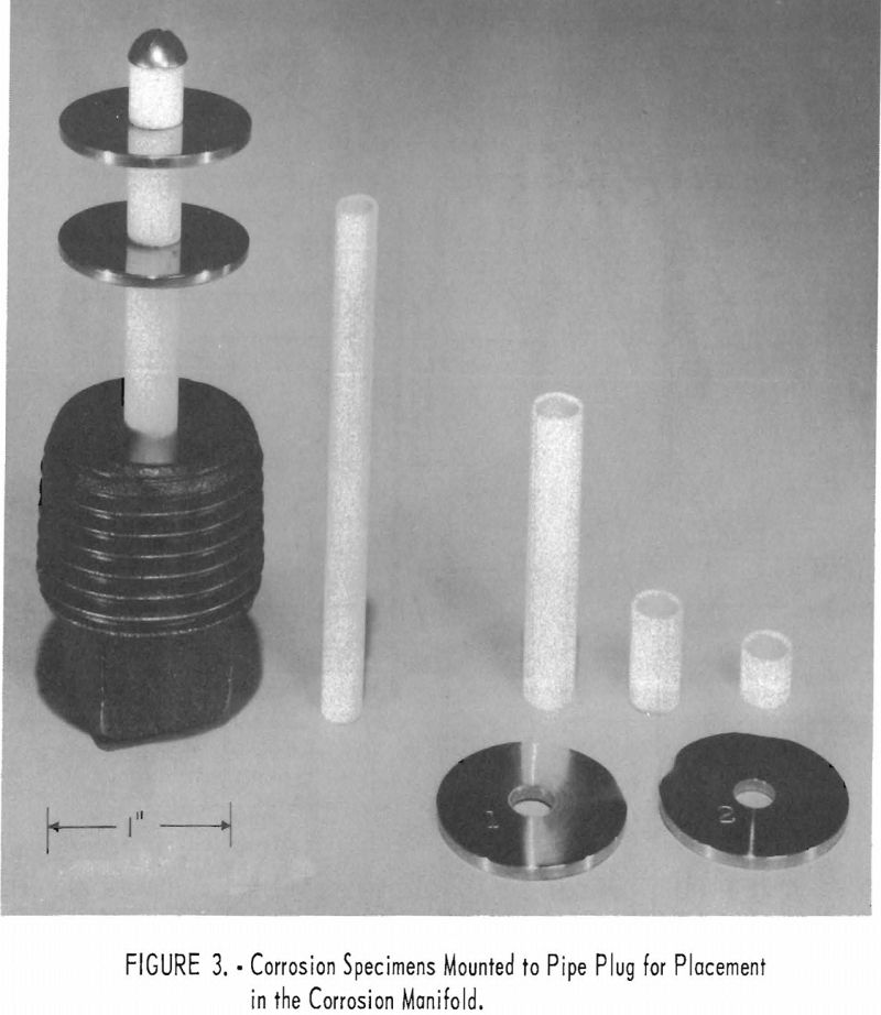
The initial phase of the experimental program was designed to determine the heat-transfer characteristics and corrosion resistance of various metals which might be used as materials of construction. The exhaust line was constructed from 1-in.-diameter stainless steel pipe with a manifold placed in the system designed to contain the corrosion specimens. The method used to mount the specimens on a 1-in. pipe plug for placement in the manifold is shown in figure 3.
At the conclusion of the first phase of the experimental work a steam turbine was added to the system to determine what effect the salt-laden steam would have on the turbine nozzle and blading. The turbine was of the impulse type with two velocity stages and was directly connected to a ½-kw., d. c. generator.
Figure 4 is a sketch of the equipment with the turbine added. Figure 5 shows the upper part of the reactor and the installed turbine.
The second phase of the experimentation was designed to study the pipe-plugging problem with larger pipe sizes, and at the velocities expected to be used on the Gnome project. The equipment was modified by replacing the 1-in. exhaust system with a 3-in.-diameter pipe. Since a 3-in. pipe with a gas velocity of approximately 100 f.p.s. would remove heat at a greater rate than the system could generate heat, it was necessary to use a closed loop and circulate the gases through the closed system. A jet type blower was used to circulate the hot gases. Preheated dry compressed air was used to operate
the blower, and a bleed-off line was provided to maintain the proper gas pressure in the system. This arrangement is illustrated in figure 6.
Experimental Procedure
The salt bath temperature control and the internal heaters were regulated to maintain a salt bath temperature of about 825° C. (1,517° F.). Depending upon bath depth, under standby operation, it required from 4-½ to 6-½ kw. of electrical power input to maintain the temperature. The voltage-amperage relationship was also dependent on electrode immersion. For example, at an immersion of 38 in. the voltage required for 6-½ kw. was about 6-½ v. and 1,000 a. The power requirements necessary to maintain an operating temperature

above the melting point of salt during a run depended upon flow rates of the gases, but ranged from 7 to 13 kw., which was from 20 to 40 pct. of the capacity of the heating system.
For the initial experiments sodium chloride was used as the molten salt. To determine the effect of the ratio cavity volume to salt surface on the amount of heat that could be transferred to the effluent gases, two separate salt depths were studied. The first few runs were conducted at a salt bath level of about 20 in. and will be referred to as the deep-cavity runs. The cavity above the molten salt surface was 52-½ in. deep and 27 in. in diameter. In order to fill the reactor to a depth of 20 in., 560 lb. of sodium chloride of 99.9 pct. purity was used.
Measured quantities of dry air with a known inlet temperature were passed over the salt surface. Four flow rates were maintained, averaging 3.2, 9.8, 25.0 and 34.5 lb. of air per hour, respectively. Each flow rate was maintained long enough to achieve steady conditions. For most of the runs the temperature of the salt was maintained at a constant level by varying the needed electrical energy through the mild steel heaters.
The temperatures of the effluent air were measured near the center of the cavity, near the exit port, and inside the exhaust line after the first bend. Other temperature measurements were also continuously recorded from

the outside reactor surface above and below the salt level, and from the outside surfaces of the lid and exhaust pipe.
Following the tests of passing air over the salt surface, steam was generated in the reactor. The air inlet pipe was replaced with equipment for injecting water onto the surface of the molten salt. Water was fed from a low-head tank which was open to the atmosphere. The steam pressure inside the reactor was automatically limited to the low gravity head of the feed water supply. The discharge nozzle had a single 3/32-in.-diameter orifice, which limited the flow rate to a safe value.
Before steam generation was started, all air was removed from the reactor and exhaust lines by thoroughly flushing the system with helium. This precaution was necessary to prevent the possibility of forming an explosive mixture of air and hydrogen. The formation of hydrogen was possible by the reduction of gaseous water by the hot steel reactor walls.
Steam was generated at six flow rates ranging from 11.52 to 29.3 lb./hr.
An additional 600 lb. of sodium chloride was added to the reactor, which reduced the cavity depth to 34 in. Only one run was made at this depth; it consisted of passing 10.35 lb. of air per hour over the salt surface.
The cavity depth was further reduced to 27 in. by adding other materials to the salt to obtain a salt composition approximate to that which would be found at the Project Gnome site. This gave a total molten-salt depth of 45 in. with approximately 1,420 lb. of salt. The total weight of materials charged and the salt mixture composition are given in table 1.

Samples of the salt mixture were taken after the impurities were charged and melted into the bath. After the experiments with steam generation were concluded, the melt was sampled again to determine any change in the composition.
The following experiments were then performed in the shallow-cavity reactor:
- Air was passed over the molten salt at flow rates of 3.55 to 21.2 lb./hr.
- Air was bubbled through molten salt at flow rates ranging from 3.4 to 18.1 lb./hr. The inlet air was discharged into the bath at depths of 6 to 18 in. below the salt surface.
- Pregenerated steam was passed over the molten salt at flow rates of 5.39 to 15,5 lb./hr. To observe the effect of a salt crust surface on the salt entrainment rate, an additional run was made in which steam was passed over the surface of hot solidified salt.
- Steam was generated over molten salt. In the previous deep-cavity experiments, violent spattering of the salt was encountered owing to a relatively large stream of water squirting directly on the salt surface. A new nozzle was made with three 1/32-in. holes drilled radially. This new configuration with three fine sprays allowed steam to be generated without violent eruptions taking place at the salt surface.
- A small steam turbine was operated on steam which was generated over the molten salt. The object was to determine the effect of the salt-laden steam on the turbine nozzle and blades. Because the safe pressure limitation of the cell was about 3 p.s.i.g and in order to obtain a sufficient pressure drop through the turbine, it was necessary to operate the exhaust side of the turbine at reduced pressure by using a condenser and vacuum pump in the system.
At the conclusion of the first series of tests the reactor was cooled to allow the salt to freeze for examination of the apparatus and to determine the extent of corrosion of the reactor. The reactor was filled with inert gas and sealed while it was in standby condition waiting for modifications to the exhaust system.
The 3-in.-loop was mounted to the lid of the reactor. Preheated compressed air was fed in through the jet of the blower. The procedure was to circulate the hot gases through the chamber and loop until the entrained salt plugged the pipe. Gas velocities ranged from 3 to 200 f.p.s., which includes the 100-f.p.s. velocity planned for Project Gnome. The main stream flow rate was determined from the flow velocity, as indicated by a pitot tube arrangement. The quantities of salt entrained and the zone of salt deposition as a function of gas velocity and zone temperature were noted.
Air temperatures and salt entrainment rates were changed simultaneously by regulating the temperature of the molten salt. The amount of salt entrained was determined by passing the bleed-off air (same amount of air as that used by the jet blower) through a distilled-water scrubber and subsequently analyzing the water.
One stainless steel gate valve and one semisteel plug valve were installed in the loop to determine how they would be effected by the salt deposits. The lubricant in the plug valve was replaced by powdered graphite because of the high temperature of operation.
The 3-in.-pipe closed-loop studies showed that the problem of salt plugging of the pipes was not eliminated by increasing the gas velocity and pipe diameter. Therefore, a series of tests was planned, to determine the effects of reversing the gas flow, the smoothness of the pipe surfaces, and the ability of backwashing the exhaust pipes with water to eliminate salt plugging. The salt was again frozen, and the equipment was put in standby condition until the modifications were made so that liners or sleeves could be added to the loop.
The cell outlet was provided with a number of sleeves, using polished sections of Hastelloy-B, Inconel-X, stainless steel type 304, and fused quartz. For high-velocity tests a special liner was fabricated having a constricted section of 1.90 in. ID as compared with a regular diameter of 2.8 in. ID. The same experimental procedure of using a jet blower to force air through the loop that was previously described was used, with the exception that the pipes were not allowed to plug completely. On some tests the direction of the gas flow was reversed by inverting the jet blower assembly. The original cell outlet pipe then became the inlet and vice versa.
Attempts to flush out existing deposits with water spray were made while the deposits were still red hot. The liners were quickly removed from the cell outlet, and the water or water and steam were sprayed into the removed liner with a lance having radial jets at the end.

Experimental Results and Discussion
Heat Transfer
In the evaluation of the heat transfer, an accurate determination of the amount and temperature increase of the thermodynamic fluids were of primary importance. The location of the various points of temperature measurement is shown in figure 7. Table 2 shows the various temperatures of the different runs at the several locations.
The average temperature of the gas contained in the cavity, as well as at its outlet, was assumed to be approximately equal to the actual temperature measured near the center of the cavity. During the latter part of the work the equipment was modified, and a shielded thermocouple was placed in the cavity near the outlet. The outlet gas temperature was within 2 pct. of the temperature of the gas near the cavity center. There was a temperature drop of about 100° F. through the steel shell owing to the temperature gradients between the contents of the reactor and the outside of the system. There were heat losses along the exhaust pipe; therefore, the drop in temperature from the cavity to the point of measuring temperature in the outlet pipe depended upon the gas flow rate.
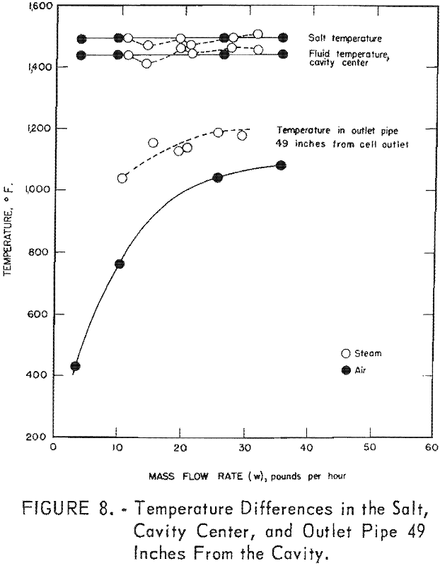
Figure 8 presents the relative amount of heat lost from the system in the exhaust line as a function of the mass flow rate for steam and air. This plot shows that with steam there is less difference between the salt and cavity temperatures as well as less temperature drop along the outlet pipe. The latter phenomenon is primarily due to the higher heat capacity of steam.
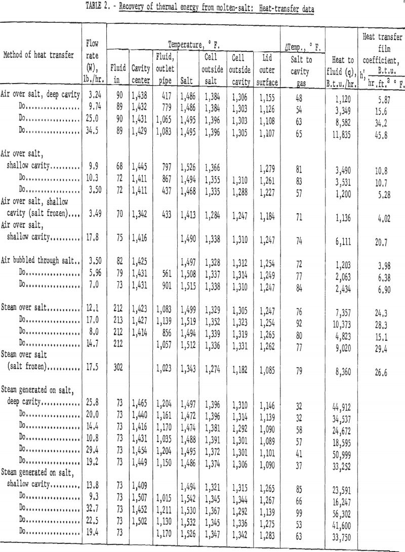
To determine the quantity q, of heat removed from the system in B.t.u. (British thermal units) per hour, the mass flow rate for air in pounds per hour was multiplied by the mean specific heat and the temperature difference between the inlet air and the gas near the cavity center, as shown by the following equation:
q = w Cp ΔT.
For runs in which steam was used as the output fluid, the amount of heat was calculated by multiplying the flow rate by the difference in enthalpy of the steam at the cavity temperature and the steam or water entering the cell. The enthalpy values used were obtained from steam tables for the respective temperatures. The values of q are listed in table 2 and plotted as a function of mass flow rate in figure 9.
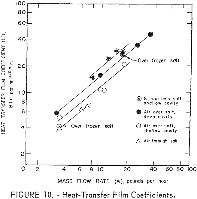
When either air or pregenerated steam was heated over the salt, a defined heat-transfer film coefficient (coeff.), h’ (B.t.u. /hr., ft.² ° F.), was calculated for each run by the following relationship:
h’ = q/As Δ Ts-c
where As is the area of the salt surface, and Ts-C is the temperature difference between the salt and the cavity.
For this calculation it was assumed that the net effects of the lid and cavity walls were negligible on heating or cooling the gas as compared to the salt surface. These data are also given in table 2 and are also plotted against mass flow rate in figure 10.
From the data presented in table 2 it is evident that satisfactory maximum gas temperatures were obtained; as a matter of fact there is less than 100° F. difference between the salt temperature and the gas temperature at the center of the cavity. As shown in figure 8 the maximum gas temperatures remained fairly constant in the cavity center even at increased flow rates. Evidently the source of heat was large compared to the demands that were placed on it.
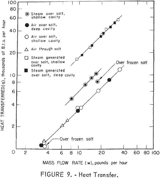
The number of cavity mass changes per hour in the Bureau of Mines reactor were in the range of approximately 740 to 20,000 times as many as anticipated on the Gnome project. As the transfer of heat to the cavity fluids from the salt surface was so effective in the various tests, the temperature of the gases in the cavity at the Gnome experiments should approach the molten-salt temperatures. The data given in figure 9 show that the cavity depth had very little effect on the amount of heat removed. These data show that steam was more effective than air and that steam generated within the system was the most effectual in heat removal. Although there were only two tests in which the salt surface was allowed to freeze, one with steam and one with air, it seems that if the salt freezes and forms a crust, the rate of heat removal is decreased, especially with steam.
Heat-transfer film coefficients relate the total rate of heat transferred by various means, to the area and temperature difference involved. No coefficients were calculated for steam generation because of the phase change from liquid to gaseous water, and because the actual area of heat transfer was unknown.
In the case of turbulent flow, the heat transfer film coefficient usually follows a general law of the form,
h’ = Cwn
where C is a constant, w the mass flow rate, and n is an exponent. By plotting h’ against w on a log-log plot, a straight line should be obtained. The exponent n is equal to the slope, and the constant C is determined from the intercept on the h’ axis when w equals unity. The following equations fit the straight line curves of figure 10.
Air over salt, deep cavity h’ = 2.11 w0.87
Air over salt, shallow cavity h’ = 1.6 w0.87
Air through salt, shallow cavity h’ = 1.3 w0.87
Steam over salt, shallow cavity h’ = 2.6 w0.87
The heat-transfer film coefficient is found from the above equations to be
h’ ~ w0.87,
or, since the cross-sectional area for flow is constant,
h’ – G0.87,
where G is equal to the pounds per hour per square foot.
It has been determined that the combined processes for heat transfer are strongly influenced by forced convection. For cylindrical shapes, the relationship is as follows:
h’ – G0.8
Heat was also transferred to the gases by radiation from the salt surface and sublimation of salt vapor. Diatomic gases are poor absorbers of radiation in this temperature range, and the heat transferred to air by radiation would be small. Since a water molecule has three atoms and hence more energy functions to absorb radiation, heat transfer should be more important with water. A study by Ramey shows that heat transfer by radiation to steam may account for 15 pct, of the total convection radiation transfer at 1,000° F. and at low Reynolds numbers. The amount would be difficult to estimate, but there should be some contribution to the total heat transfer by radiation to the solid salt particles suspended in the cavity.
A calculation of the amount of heat transferred by sublimation of the salt from the surface and subsequent entrainment in effluent steam indicates that sublimation would account for only about 2 to 4 pct. of the total.
For recovering heat from an underground cavity, steam appears to have the following advantages over air.
- Because of the larger heat capacity, there is a smaller temperature drop along the exhaust pipe, and lower flow rates may be employed for equivalent power input.
- The heat transfer coefficient is higher for steam than air.
- Water can be added to the cavity under its own gravity head, whereas air would have to be forced through the system by being pumped at high velocity through the pipes, which would result in considerable expenditure of energy.
Steam Turbine Operation
A small steam turbine was successfully operated on steam generated over molten salt. The turbine was operated for almost 10 hr. before it was dismantled and inspected for corrosion or plugging with entrained salt.
Typical turbine operating conditions are listed in table 3.

No impairment of operation or vibration of the turbine was observed. After the operation an inspection showed that no salt had deposited on the high-velocity passages, such as the nozzle and turbine blades, but coatings of soft, powdery salt had collected in layers of ½ to 2 mm. in thickness on the surfaces in low-velocity passages. The steel alloy from which the turbine blades were made was not known; however, the original bright semi-polished surfaces were blackened during the operation, possibly by corrosion products such as sulfides or oxides from reactions between the metal surfaces and the hot gases.
Chemical Reactions and Chemical Composition of Effluent Gases
Chemical reactions were apparent between the air or steam with the reactor walls and/or the salt. The acidity and the constitution of the effluent material depended to a certain degree upon flow rate, the constitution of the salt mixture, and whether air or steam was passed over the salt.
The carryover of acid equivalent was determined by measuring the decrease of pH of the scrub solution and was expressed as grams of hydrogen ion per kilogram of fluid passed through the salt cavity. The production of sulfur was determined by chemical analysis of aliquot parts of a slurry of the steam condensate. Iron determinations were also made on the steam condensate and air scrubber.
The results of the acid carryover and the sulfur contamination are given in table 4, as compared to the bath composition and process of heat removal.

In general the acid carryover increased with flow rate, and the acidity was greater when water or steam was the fluid rather than air. The sulfates in the Gnome salt apparently increase the acid carryover especially if air is used as the fluid. For air passed over sodium chloride the acid carryover ranged from 0.37 to 9.04 x 10 -4 g H+ per kg. of fluid, whereas with air over salt of Gnome composition the range was from 23.5 to 278 x 10 -4.
In tests in which air was the working fluid, the amount of iron that was carried over could be roughly correlated to the amount of hydrogen ion produced. It was assumed that ferric chloride was formed at low activity by the reaction between oxygen, iron, and the sodium chloride and was subsequently distilled at a low partial pressure from the system. The ferric chloride would then hydrolize in the scrubber to produce hydrogen ions.
The increased acid carryover by water from the sodium chloride bath may be due to the reaction between water and sodium chloride to produce hydrogen chloride gas at low activity.
Thermodynamic calculations indicate that ferric chloride can be produced at very low activity from the reaction between oxygen, iron, and sodium chloride, and that hydrogen chloride can be produced at a little higher activity by the reaction of water with sodium chloride. By the addition of sulfates to the sodium chloride, reactions can occur to also produce hydrogen chloride with a fair partial pressure.
Considerable variation was noticed in the chemical composition of the effluent fluids, and the data for the various runs are not easily correlated with flow rates or depletion of the components from the molten salts.
The relative amount of the various components in superheated steam was determined for three runs and is listed as weight-percentage in table 5. The salt in the steam was composed of sodium, calcium, magnesium, and iron chlorides and sulfates, with sodium chloride as the paramount constituent.

A hypothesis can be advanced that for a Gnome type of operation the amount of elemental sulfur produced would be much less than in these experiments, because the reduction of the sulfates to sulfur no doubt depended upon the reducing potential of the iron in the reactor. The acid carryover of hydrogen chloride content of the effluent gases would probably be of the same order of magnitude at Gnome as was encountered in this study because of the following reaction to produce hydrogen chloride:
NaCl + H2O → HCl + NaOH.
If it is assumed that the free energy of formation of NaOH is about -65 kcal (kilocalories) at the temperature of the operation (the free energy of formation of the other components (2) is known), the free energy of the above reaction at 1,100° K. (827° C.) was calculated to be 29.8 kcal. Since the activity of both H2O and NaCl is nearly unity, this corresponds to Kp = pHCl αNaOH = 10 -6. As sodium hydroxide is soluble in sodium chloride above its melting point, the activity of sodium hydroxide would probably be in the range of 0.1 to 0.01. This calculation would therefore give a value for the partial pressure of HCl in the range of from 10 -4 to 10 -6 atmospheres. An average value calculated from table 5 is about 10 -5 atmospheres.
From these calculations it is expected that the acidity of the condensate which will be encountered at Gnome will be about the same as would be calculated from the data of table 5.
Corrosion Rates of Materials of Construction
Corrosion specimens of various metals were placed in the outlet gas stream to determine the relative resistance of the metals to corrosion in order to help in ascertaining the best metals for materials of construction.
The specimens were weighed and the diameter and thickness were measured before exposure. They were weighed again after the corrosion products had been removed. Stainless steel, Monel, steel, and copper specimens were exposed to the exhaust air for 32.3 hr. and to outlet steam for 31.5 hr. Specimens of titanium and titanium alloy containing 0.17 pct. palladium (Pd) were exposed to the air exhaust for 23.3 hr. and to outlet steam for 31.5 hr. A single specimen of 50 pct. titanium-50-pct. tantalum alloy was exposed to the outlet air for 23.3 hr. and then to the outlet steam for 31.5 hr. The temperature in the corrosion test manifold ranged from ambient temperature to 450° C.
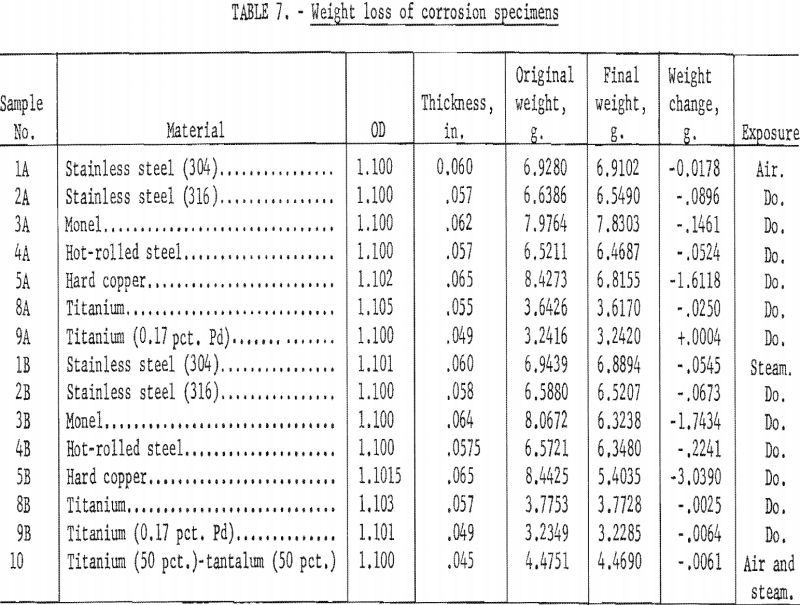
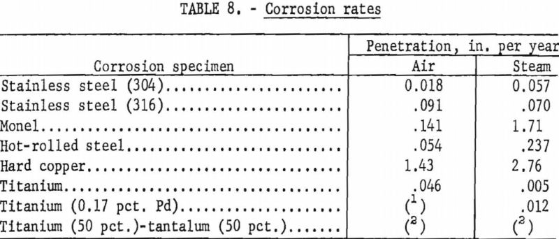
Microscopic (X40) examinations were made of the specimens before the corrosion products were removed, and observations made are given in table 6. The visual observations indicate that the titanium and titanium alloys were the most resistant to corrosion and erosion. The data of table 7, which gives the weight loss of the specimens due to corrosion, also show that titanium alloys were superior, with the steels being next best. Both Monel and copper suffered severe corrosion. For sample 9A, the slight increase in weight may have been due to not being able to completely remove the corrosion products. From table 7 and the photograph of the corrosion specimens figure 11, it is apparent that steam was more corrosive than air. Based on the data in table 7, the corrosion rates have been calculated as inches penetration per year (IPY) and are tabulated in table 8.
In general, the data of table 8 sustain the above observations and conclusions.
Salt Entrainment
As the fluids left the reactor, the salt entrained by the air or steam collected in specific zones of the exhaust line, such as elbows or other areas where the direction of the gas flow was changed. After a period of time, the deposited salt restricted the gas flow through the exhaust lines to the extent that it was necessary to terminate the operation and mechanically clean the pipes before continuing with another run. The amount of salt entrained was determined by collecting the effluent air in a water scrubber and the steam in a condenser and then analyzing the solution for salt. The effluent gases passed through about 18 ft. of pipe before the salt was collected; therefore, the accumulation or depletion of salt in the test pipes may account for some of the variance of the data.


Tabulated in table 9 are the data that show the amount of salt entrained by the effluent gases for the several methods of adding air, steam, or water to the reactor. It is noted that the amount of entrained salt is not directly correlated to flow rate. Also, no direct correlation could be made to the temperature of the salt nor to the cavity temperature or depth. It was observed that air, if passed through the salt bath, entrained more salt than air passed over the surface. Water and steam both entrained more salt than was generally carried by air.
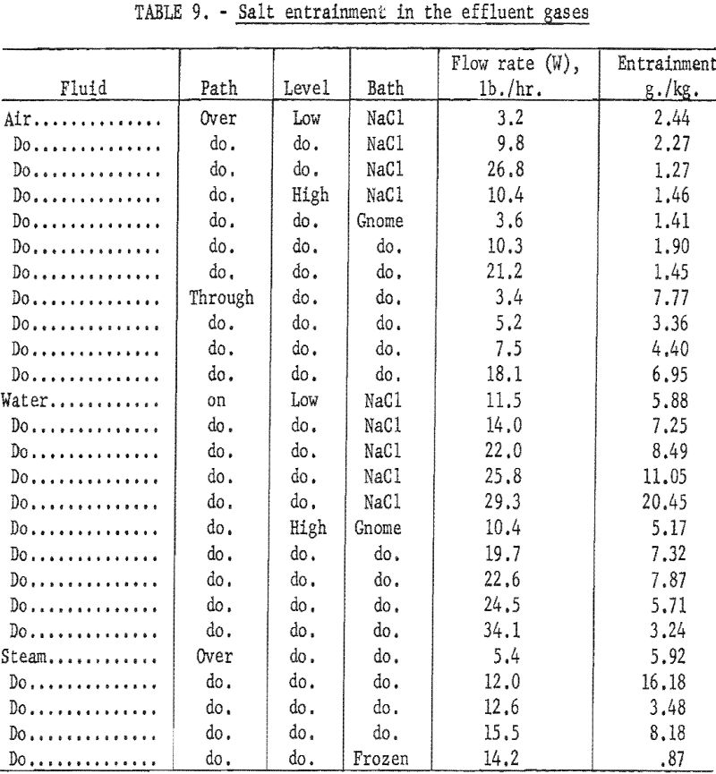
The higher values of entrainment for water and for air passed through the salt were probably due to the greater turbulence of the salt surface. Salt entrainment was much less for steam over the frozen-salt surface. In general, the amount of salt carried with the effluent gases was greater than would be expected from direct calculations of the vapor pressure of the salt.
The temperature of the salt surface ranged from the melting point of sodium chloride, 1,474° F. (1,074° K.), to 1,542° F. (1,112° K.). The vapor pressure of sodium chloride follows the following equation (2, table D):
log Pmm = -11,530/T -3.48 log T + 20.77
where T is the temperature in ° K.
From this equation the vapor pressures of sodium chloride are 0.31 and 0.63 mm. for 1,474° and 1,542° F., respectively. From these vapor pressures the theoretical amounts of sodium chloride entrained in effluent air are 0.83 and 1.67 g./kg. and for steam 1,33 and 2.66 g./kg., for the respective temperature. The values observed and tabulated in table 9 were about 8 to 10 times the calculated amount in certain instances.
The temperature difference between the salt surface and the center of the cavity in a run was from 40 to 100° F. It was also determined that the particle sizes of the entrained salt ranged from 1 to 20 µ (microns). This particle size is just larger than colloidal size; therefore, the settling rate should be extremely slow. These salt particles can be accounted for by the vaporization of the salt from the liquid surface and the condensation to the solid state in the cooler zones of the cavity.
Many factors such as the particle size, turbulence, temperature and temperature differences, number of salt crystallization nuclei, and crystal growth rate, determine the amount of salt that will be suspended at any particular time. The material coming from the reactor consisted of the suspension of salt in the gaseous medium, and therefore the concentration of the salt in the suspension varied but could be and was generally higher than expected from any particular factor such as the vapor pressure of sodium chloride.
Because of the complexity of the mechanism of salt entrainment by the effluent gases, correlation of the amount of entrainment to any particular variable is difficult and would, in all probability, be misleading.
It is proposed that the mechanism of transfer of salt particles from the reactor was that the gases which flowed through the reactor swept the suspension of salt particles from the cavity and into the exhaust system.
Pipe Plugging
In the first series of experiments in which the exhaust lines were made from 1-in. stainless steel pipe, the system sometimes became inoperative in as little as 2 hr. From the investigation it was determined that the major problem of heat removal was plugging of the exhaust system. From the first experiments it was also recognized that the chief variables were the amount of entrained salt, the diameter of the pipe, the flow velocity, and the temperature of the suspension.
To obtain a high-velocity flow through a large-diameter pipe (3-in.) with the limited heating capacity of the reactor, it was necessary to circulate the effluent gases through a closed loop.
The 3-in.-pipe loop was plugged with salt deposit after an operation of 6-¼ to 35-½ hr, depending directly upon the rate of salt entrainment. Comparing the data of the 3-in.-pipe loop to that of the 1-in diameter pipe indicates that the time required is approximately proportional to the pipe diameter. Some evidence showed that higher gas velocities slightly delayed the plugging. None of the various operational procedures attempted prevented the plugging of the system. The variations included using pipe surfaces of different materials such as Hastelloy B, Inconel X, stainless steel type 304, and fused quartz, as well as very high and very low flow velocities. Reversal of the gas flow through the loop did prolong the time of plugging, even beyond the effect of doubling the cross-sectional area, but eventual plugging was inevitable.
The temperature of the suspension had a definite effect on the nature of the salt deposit in the pipe. At the higher temperature (above 1,300° F.) at the inlet end of the exhaust pipe, the plug appeared to be somewhat sintered, which resulted in a fairly compact sticky deposit. The dense deposit was difficult to remove. Along the straight portions of the pipe the salt was transported as a suspension. In the zones where a decrease in gas velocity or change in flow direction occurred, the salt collected as a light, dry, fluffy deposit. The long-radius bends (8 to 12 times the pipe radius) were vulnerable to plugging at temperatures above 850° F., at velocities between 70 and 125 f.p.s.; however, these deposits were also dry and easily removed by high-velocity air jets accompanied by heavy vibration. When the suspension temperature dropped below the above temperature, the salt behaved as a dry powder and was easily carried along with the gas stream. As a simple analogy, the system behaves like drifting snow, The salt deposits at the higher temperatures are similar to wet snow. At the lower temperatures the salt is easily carried along by the moving gas stream, similarly to the drifting of dry snow.
The 3-in.-stainless steel gate valve was workable throughout the testing In spite of exposure for 106 hr. at temperatures above 1,100° F. Some salt did become wedged in the valve seat after repeated closing, and the valve could not be completely closed at the termination of the operation. The plug valve, at 900 to 1,100° F., remained in operating condition until the lubricant, which was not replaced, was destroyed by the heat.
While the formation of the salt deposits was not prevented, deposits in vertical pipes could be removed by flushing with water or a water-steam mixture. Radial jets of wet steam from a lance probe were particularly effective in removing the light deposits.
The greatest difficulties will probably be associated with the entrainment in the working fluid of salt particles which have a tendency to plug the piping system. The seriousness of this problem is increased by the fact that the obstruction would occur at relatively inaccessible depths, where gas temperatures are highest. Very little can be done to prevent the deposition of salt in pipes operating above 1,300° F. One possibility, which was not tested, would be to prevent salt vapor from coming into contact with the working fluid. This might be done by laying an impervious blanket or coating of inert material over the molten-salt pool. Without some positive method of prevention, provisions to clean the exhaust pipe periodically, seem imperative.
Conclusions
The following conclusions can be made from this study:
- The transfer of heat from a molten salt to air, steam, or water was very effective and satisfactory gas temperatures were obtained, but large heat losses may be encountered in transporting the hot gases over long distances.
- The heat-transfer film coefficient for salt to the fluids in these experiments followed the general law h’ ~ w0.87. Therefore, extrapolation of the data to other similar operational conditions is facilitated.
- Water was more effective than air in removing heat from the system, but water entrained more salt in the effluent gases and the acidity of the condensate was higher.
- The exhaust gases collected and scrubbed in distilled water lowered the pH of the water considerably, and it will be necessary to contend with acid conditions.
- A small steam turbine was operated successfully by steam generated over molten salt without any apparent damage to the moving parts by the entrained salt.
- There was sufficient salt entrainment by the effluent gases to cause considerable trouble in plugging of the exhaust line, and none of the operational techniques tried were effective in eliminating this problem.
- Salt deposits in the exhaust line could be removed by periodic application of water jets.
