Table of Contents
This report describes a preliminary investigation of methods for recovering hydrofluoric acid (HF) from waste byproduct fluosilicic acid (H2SiF6). Fluosilicic acid is generated by plants processing phosphate rock in the manufacture of fertilizer; most phosphate rock contains 3 to 5 percent fluorine in the form of the mineral fluorapatite (Ca3(PO4)3F). When this fluorine-bearing material is treated by either acid or thermal processes, much of the fluorine is volatilized as silicon tetrafluoride (SiF4), presenting a serious air pollution problem.
However, volatilized SiF4 represents a very substantial fluorine resource. Most phosphate rock processors collect the volatilized SiF4 in scrubber towers in which the SiF4 hydrolyzes according to the reaction:
3 SiF4 + 2H2O → SiO2 + 2H2SiF6.
After separation of precipitated excess SiO2, the concentration of H2SiF6 in these solutions is 18 to 24 percent.
There is a growing, but limited, market for H2SiF6 in the fluoridation of municipal water supplies; however, the greater part of this material is dumped into storage ponds and neutralized with lime to minimize pollution of local water resources. The very strong bond between fluorine and SiO2 has been the principal barrier to using HgSiF6 as a major source of fluorine. Recently however, a patent has been granted for a process that describes the use of H2SiF6 for the production of synthetic cryolite (Na3AlF6). In this process the SiO2 is separated from the H2SiF6 solution by hydrolysis with sodium carbonate (Na2CO3) and the resultant sodium fluoride (NaF) solution is reacted with sodium aluminate (NaAlO2) to precipitate Na3AlF6. An Austrian firm has described a method for utilizing H2SiF6 for producing aluminum fluoride (AlF3) for use in the aluminum industry. Previous Bureau of Mines investigations have included studies on defluorinating siliceous fluorspar by hydrolysis at high temperatures, and on preparing AlF3 and Na3AlF6 from NH4F derived by amnioniation of H2SiF6. Additional studies have been made on separating HF from gaseous mixtures of HF-SiF4-H2O.
The present study describes two approaches to the recovery of silica-free aqueous HF by high-temperature hydrolysis of H2SiF6. One approach was the direct volatilization and hydrolys is of H2SiF6 in an externally heated tube according to the reaction
H2SiF6 + 3 H2O → H2SiO3 + 6 HF.
The second approach was steam hydrolysis of a mixture of CaF2 and SiO2 formed by neutralizing H2SiF6 with lime. This procedure may be expressed by the following two general equations:
H2SiF6 + 3Ca(OH)2 → 3 CaF2 + SiO2 + 4H2O……………………………………..(1)
CaF3 + SiO2 + H2O → CaSiO3 + 2HF…………………………………………………..(2)
Equation 2 represents a procedure reported by Fugate and Banning for recovery of HF from siliceous fluorspar up to 1,420° C.
The H2SiF6 used in this investigation was an unrefined product from the scrubbers of a phosphate fertilizer company. Several batches were used. Except where noted, the acid contained 274 g/l fluorine and 80 g/l silicon. Although this product is referred to as fluosilicic acid and assigned a formula, in practice it did not show an exact composition. Frequently an excess of silica was present because silicic acid is soluble in H2SiF6.
The scope of the investigation was limited to determining reaction characteristics, operating limits, and the effect of varying conditions on concentration, yield, and purity of the recovered HF. Except for the work reported on the use of fluid-bed reactors, all reactions were carried out in static-bed systems. Collection of information from this equipment was oriented toward its application to continuous, moving-bed equipment which would be necessary for practical application of the data collected. The composition of recovered HF was evaluated for its application to existing techniques of purification, concentration, and use.
Experimental Procedures and Results
Direct Hydrolysis of H2SiF6
Preliminary studies established that hydrolysis took place when H2SiF6 was volatilized in a flash vaporizer and the vapors were passed through a quartz tube externally heated to 1,000° C, yielding a mixture of HF and H2SiF6. A deposit of SiO2 was formed on the sides of the tube. The reaction proceeds above approximately 750° C according to the following reaction:
H2SiF6 + 2H2O → SiO2 + 6 HF.
Water-cooled copper condensers were used to recover the HF product. Efficiency was increased by packing the tube with pieces of quartz to give a greater surface for SiO2 deposition and heat exchange. It was found empirically that at about 750° C and above, the HF formed in the reaction did not attack SiO2. In those parts of the quartz tube lying outside the heated zone, however, the reverse reaction of HF with SiO2 took place, contaminating the HF with H2SiF6.
Type 446 stainless steel (iron-chromium) was found to be resistant to attack by HF vapors under the reaction conditions. A reactor was fabricated of this material, consisting of an externally heated tube with a separate inner core. This core was composed of a central rod on which were mounted round sheet metal baffles of iron-chromium alloy; SiO2 was deposited on these baffles as hydrolysis progressed.
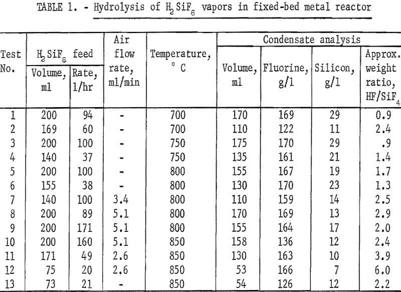
A series of tests was carried out in this equipment, testing the effect of variations of temperature, feed rate, and the effect of passing air through the reactor during hydrolysis to promote turbulence. Representative results are recorded in table 1. These results show that the addition of air, especially at low H2SiF6 feed rates, increased the degree of hydrolysis attained in most tests. Attempts to hydrolyze H2SiF6 by injecting it into air-gas and oxygen-gas flames were not successful.
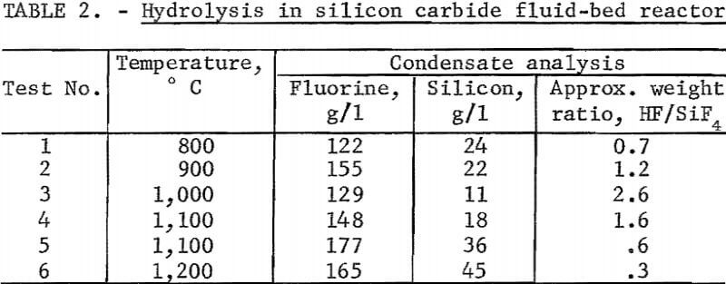
Testing established that below 1,100° C silicon carbide was not attacked by the reaction products. A fluid-bed reactor about 6 inches ID and 12 inches high was fabricated from that material and externally heated by a gas flame. Crushed SiO2 was used as the bed medium. In this unit, a series of hydrolysis experiments was carried out between 800° and 1,200° C. The unit cracked and leaked badly so that fluorine recovery figures were meaningless. Contrary to expectations, the SiO2 deposited in the bed did not accrete to the existing SiO2 particles but formed powder and separate agglomerates. Attrition of these particles and of the quartz bed material yielded a very fine SiO2 powder which was carried into the exit gas stream. Reaction of this powder with HF after leaving the heated reactor not only lowered the effective level of hydrolysis attained, but also added to the already erratic results. Above 1,000° C the reaction appeared to be inhibited, yielding, at 1,200° C, a very low ratio of HF to SiF4. Results of these tests are reported in table 2.
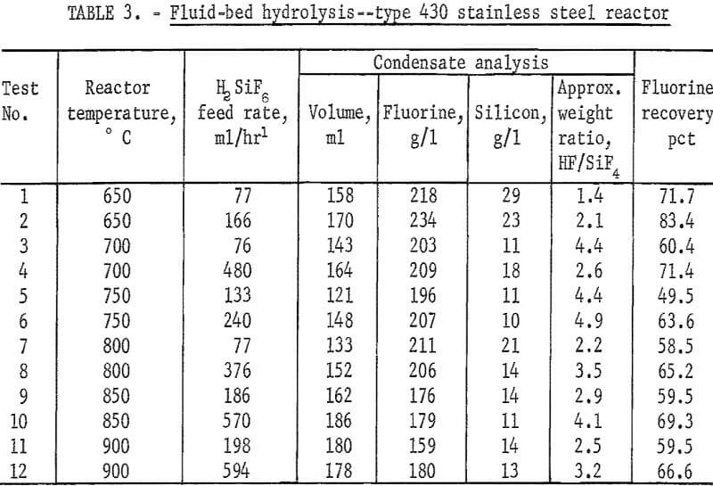
An additional series of tests was carried out at lower temperatures in a fluid-bed reactor fabricated from type 430 stainless steel, and externally heated by electricity. Quartz sand was used as the bed medium.
With a few exceptions the best level of hydrolysis was attained between 700° and 900° C. Lower ratios of HF to SiF4 were noted when lower H2SiF6 feed rates were used. Data are shown in table 3.
Although direct hydrolysis took place in all of these types of equipment, even the best results fell far short of yielding crude HF amenable to existing methods of purification and concentration. Results, even when conditions were quite precisely controlled, were poorly reproducible. No combination of reaction conditions or equipment design was found capable of overcoming the problems. At this point the direct hydrolysis approach did not seem to offer a feasible route to preparing HF. The investigation was recessed in favor of an indirect method described in the next section.
Hydrolysis of Lime-Neutralized H2SiF6
Preliminary tests, not described, established that hydrolysis took place when steam was passed through a bed of lime-neutralized H2SiF6 at about 1,000° C. The chemical reactions of lime neutralization may be expressed by the following:
Neutralization of H2SiF6 with calcium hydroxide (Ca(OH)2) in two steps:
(a) H2SiF6 + Ca(OH)2 → CaSiF6 + 2H2O
(b) CaSiF6 + 2Ca(OH)2 → 3CaF2 + SiO2 + 2H2O
In practice, Ca(OH)2 was slowly added to the acid as a slurry. Strong agitation was necessary to ensure adequate mixing of the reactants; otherwise unreacted particles remained in the slurry. Heat evolved in the reaction raised the slurry temperature to the boiling point. A series of experiments established that 3 moles of lime per mole of acid was required to bring the solution to the neutral point. At pH values above 6, no fluorine could be detected in the filtrate, showing that precipitation was complete.
An attempt was also made to carry out the neutralization with CaCO3. When this was done no heat was evolved in the reaction, but extensive foaming occurred and the product was slimy and difficult to filter.
The hydrolysis step required addition of more SiO2 to satisfy the following equation:
CaF2 + SiO2 + H2O → CaSiO3 + 2HF.
The neutralization reaction described previously yielded 1 mole of SiO2 to 3 moles of CaF2; the above reaction required the addition of 2 more moles of SiO2 to provide the 1-to-1 mole ratio of CaF2 to SiO2. The distinct possibility exists, however, that this equation does not adequately describe the reaction. Analyses of the reaction products failed to identify any other compounds. In the following discussion, therefore, all calculations of reactants are based on the assumption of the equation being valid. In the early part of these studies, silica flour was used; subsequently, quartz ground to minus 100 mesh was found to yield satisfactory results.
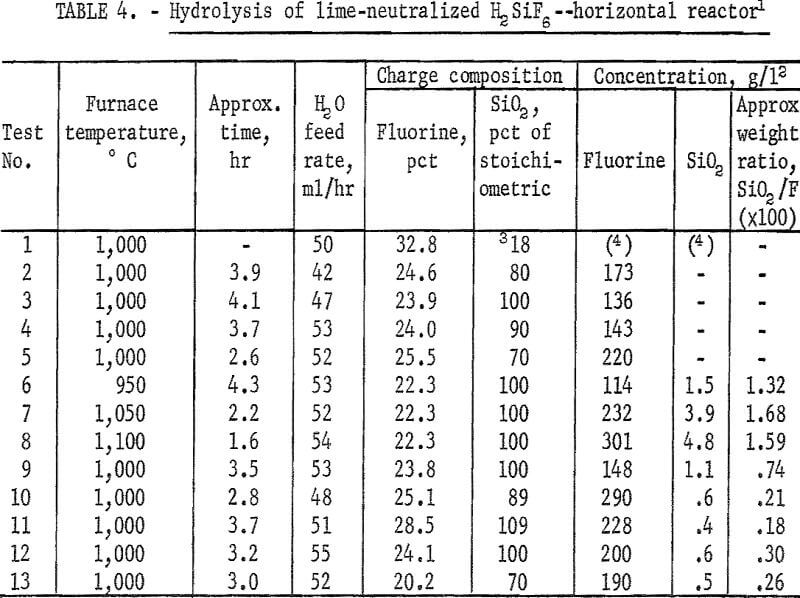
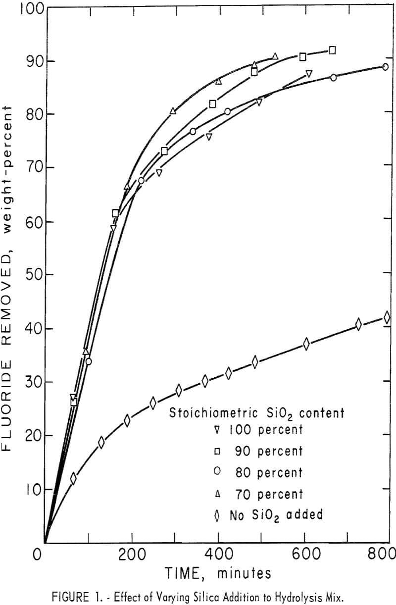
A series of experiments was carried out to establish the amount of SiO2 necessary for the hydrolysis reaction. Results, shown in figure 1, compare the effect of adding no SiO2 and of adding 70, 80, 90, and 100 percent of the calculated SiO2, requirements for hydrolysis. Except for the single test containing only SiO2 derived from H2SiF6, the results show very little difference in either removal rate or overall recovery of fluorine. Data are shown also in table 4, tests 1-5. In subsequent tests, SiO2 in the reaction mix was maintained at, or near, 100 percent of the stoichiometric value to ensure that enough SiO2 was always present to satisfy the reaction requirements.
The calculated amount of ground quartz was stirred into a neutralized batch of slurry just before filtering in a basket centrifuge. The resulting wet filter cake was of the proper consistency to be passed through an extrusion pelletizer. In early small-scale work, pellets of about ¼-inch diameter were used. Later, pellet size was increased to about ½-inch diameter; the larger pellets were easier to prepare. They were dried before being loaded into the hydrolyzer.
In early tests, hydrolysis was carried out in an externally heated type 446 stainless steel tube about 1½ inches ID. This was horizontally mounted and electrically heated. Water was metered to a flash vaporizer that was mounted at one end of the tube. A water-cooled copper tube at the other end was used to recover HF solution.
In operating this system, a charge consisting of 165 grams of pellets was placed in the reactor tube and positioned so that the entire charge lay within the zone of maximum heat. This avoided the possible back reaction of HF with SiO2 in the pellets, which could take place at lower temperatures. Pellets were held in place by a piece of stainless steel screen. After connecting the vaporizer and condenser systems, the reactor was heated to the desired temperature; this was measured on the outside of the reaction tube. Steam was then passed in by starting a measured flow of water to the flash vaporizer which was heated to 300° to 400° C. Use of this system avoided the difficult problem of trying to meter steam at a low flow rate.
The volume of HF solution was measured at intervals and the solution was analyzed for its HF and SiO2 content. Fluorine was determined by filtration with thorium nitrate (Th(NO3)2) solution and SiO2 was determined colorimetrically by the silico-molybdate technique.
Unlike previous experience with direct hydrolysis of H2SiF6, the SiO2 content of the solution was low. It was found to be less, frequently much less, than 1.8 percent of the fluorine content of the solution, a level considered acceptable for experimental purposes. Although specific standards do not exist for crude HF, this opinion was based on the specifications for acid-grade fluorspar, which permit 1.5 percent SiO2. This amount represented approximately 3 percent of the contained fluorine. Commercially, after acidulation of fluorspar, SiO2 is removed from crude HF by adding NaF to precipitate SiO2 in the form of insoluble Na2SiF6.
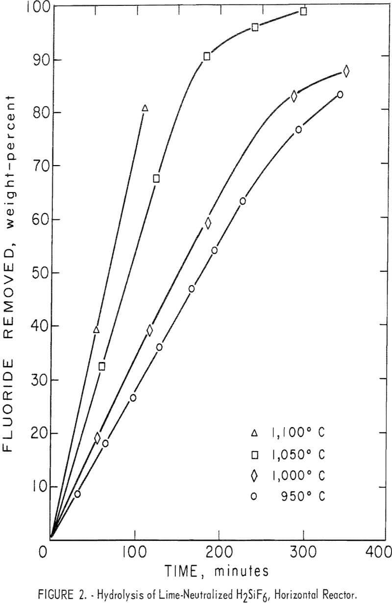
The effects of varying the reactor temperature were studied in a series of four experiments. Results are shown in figure 2 and table 4, tests 6-9. Hydrolysis efficiency increased with increasing reactor temperature as shown by increased HF concentration of the recovered solution. The 1,100° C reaction was terminated after 110 minutes to avoid destroying the reactor tube which was operating close to its failure point. To avoid shortened equipment life, most tests were carried out at or below 1,000° C. Results of additional tests carried out at 1,000° C are also shown in table 4.
Inspection of the curves in figure 2 shows that in the early stages of the reactions, hydrolysis took place at a fairly uniform rate as shown by the “straight-line” portion of the curves. As fluoride in the charge was depleted, fluoride removal became erratic. Most curves showed a characteristic “break” at the point at which approximately 70 percent of the fluoride had been removed from the charge. At that time the condensed product contained the amounts of HF and SiO2 shown in the tables. This limitation permitted a
better comparison of results of tests under varying conditions than was attained when the erratic effects of fluoride depletion were included.
The horizontal unit described had certain disadvantages because the quantity of material being reacted was quite small and the reaction zone was very short. Shrinkage of pellets during reaction caused a gap to form above the pellets permitting some steam to pass across the bed rather than through it.
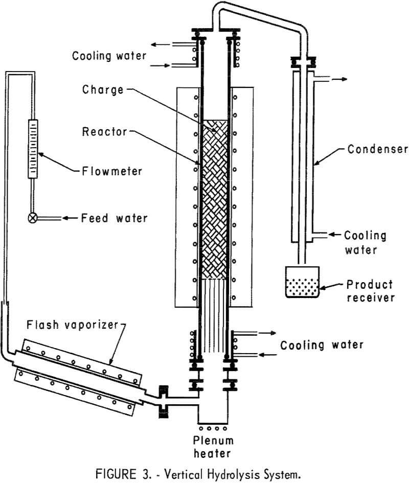
A new vertical reactor was designed and constructed of 5-inch OD fused quartz tubing 4 feet long. The principal purpose of changing to the larger unit was to gain the advantages of increased bed depth, more uniform steam passage through the bed, and greater scale of operation. It was heated externally by a 3-foot-long electric tube furnace. Measurement of heat distribution within the tube showed that a reaction bed up to 24 inches in depth and properly positioned could be used without extending into zones of lower temperature. Tube heads, top and bottom, were fabricated from type 430 stainless steel and were sealed to the quartz tube with water-cooled neoprene O-rings. Other O-rings used to seal the system were made from silver-plated Inconel-X,5 selected for its resistance to corrosion by HF. The flash vaporizer was a 26-inch-long copper pipe 2 inches in diameter, heated by a tube furnace. The pipe was inclined at 10° to the horizontal. At the lower end of the reactor, and connected to the flash vaporizer by a short crossover, was a heated plenum chamber. The purpose of this chamber was to remove any steam pulsations present in the small diameter exit of the vaporizer. Inside the reactor tube and resting on the lower tube head was a bundle of 15 – and 25-mm Vycor tubes 15 inches long. These were arranged so as to fill the entire cross section of the reactor tube to provide additional heating surface for the incoming steam and to support the reactor charge in the hot zone of the furnace. A stainless steel screen was placed on top of the tubes to support pellets. Extruded pellets of about ½-inch diameter were used for the furnace charge. A cross-over tube fabricated from nickel was attached to the top tube head to direct the gaseous reaction products to the condenser. This condenser was fabricated from 1-inch-diameter copper tubing surrounded by a 3-inch-diameter water jacket; the condenser assembly was 3 feet long. Condensed products were collected in an open polyethylene container. A diagram of the hydrolyzer assembly is shown in figure 3.
Any uncondensed products were exhausted through a duct placed just above the open collector to avoid contamination of the laboratory atmosphere.
To operate the system, a charge of 2½ to 3 kilograms of pellets was placed in the reactor tube, forming a bed about 16 to 20 inches deep in the zone of maximum heat. The reactor and flash vaporizer were brought up to temperature; the vaporizer was heated to 450° C and the reactor heated, for most of the tests, to 1,000° C, measured at the outside surface of the reactor tube. When operating temperatures were attained, the flow of water was started to the vaporizer at the desired rate. This caused a temporary drop in the vaporizer temperature, but recovery was usually complete within 15 minutes. The condensed HF product was collected in a polyethylene container. Samples were taken periodically and analyzed for fluorine and SiO2 content. The test was usually terminated when 80 to 90 percent of the available fluorine had been removed from the reactor charge and the solution became increasingly dilute.
The use of a quartz tube had one disadvantage. Although no reaction of evolved HF with SiO2 took place in the zone of maximum heat, the cooler part of the tube below the water-cooled head was slowly attacked. As a result,
condensed solutions were higher in SiO2 than those recovered in the horizontal metal unit by a factor of about 10. The cause of this increase was obvious on inspection of the quartz tube. For this reason, and on the basis that tests in the metal unit had established low-silica solutions as being characteristic of the reaction, SiO2 concentrations of the solutions from the large-scale tests carried out in the quartz tube were not reported.
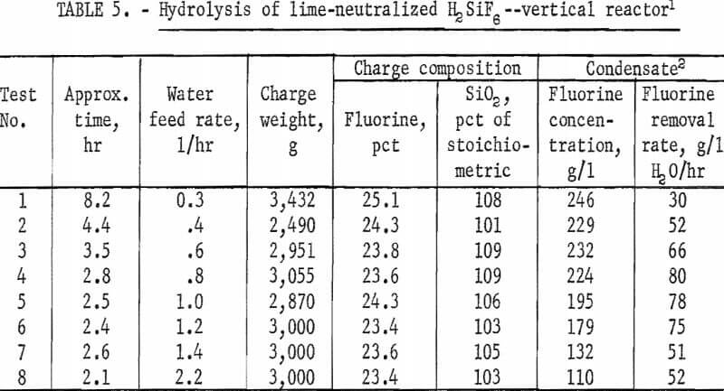
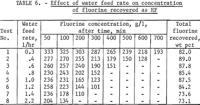
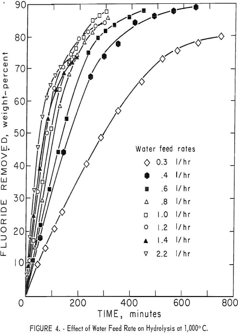
The remaining variable to be tested in this equipment was the effect of varying the water feed rate through the charge on fluorine concentration in the condensate and on the rate of fluorine removal from the charge. In this study flow rates were varied from 0.3 to 2.2 l/hr at a reactor temperature of 1,000° C. The results of this series of tests are shown in figure 4 and in tables 5 and 6. The curves in figure 4 show that in each test the reaction rate remained relatively constant, decreasing only slightly until 60 to 70 percent of the fluorine had been removed from the charge, after which the reaction rate decreased more rapidly. The data in table 5 show that a water feed rate of 0.8 l/hr resulted in the most efficient fluorine removal rate per unit of water, that fluorine concentration in condensates at each water feed rate is a function of time, and that the lowest water feed rate yielded the highest fluorine concentration.
Conclusions
Direct hydrolysis of H2SiF6 over a temperature range of 700° to 1,200° C in fixed-bed and in moving-bed systems yielded generally poor results in eliminating SiO2 from the condensed HF solution.
Reaction characteristics of steam-hydrolysis of lime-neutralized HgSiF6 were found to be the following:
- Addition of 70 to 100 percent of the calculated SiO2 requirement had little effect on hydrolysis rate or HF concentration of the condensate.
- The HF concentration increased with increasing reaction temperature over the investigated range of 950° to 1,100° C.
- The HF concentration increased with decreasing water feed rate.
- The SiO2 content of the condensed HF product did not exceed 1.8 per-cent of the fluoride content, and was usually much lower.
