Table of Contents
Ion exchange techniques have been used to recover uranium from waters pumped from uranium mines in the Ambrosia Lake district of New Mexico since about 1963. More recently., the natural flow of mine water and the recovery of uranium have been augmented by routinely spraying abandoned areas of the mine with barren solution from the ion exchange circuits. The mine waters are slightly alkaline and uranium is present in solution as the UO2(CO3)-4 complex, at an average concentration of 9 to 12 ppm U3O8. About 5 million gallons of water per day is pumped from the mines and treated by ion exchange to recover 10,000 to 15,000 pounds of U3O8 per month.
Standard ion exchange practice involves absorption of uranium on coarse bead (minus 16 plus 20 mesh), strong base, anion exchange resins contained in columns. Commonly, two columns are used in series on the absorption cycle. The columns, which operate with upflowing solution, range from 8 to 16 feet in diameter and 8 to 12 feet in height. Loaded resin is hydraulically transferred to an elution column, where the uranium is stripped by a downflowing solution of NaHCO3 or NaCl and NaHCO3. In some plants, loading and elution are accomplished sequentially in the same column.
Existing ion exchange installations are effective in recovering uranium, but the size and number of columns and the inventory of resin required are large. An investigation of ion exchange by the Bureau of Mines led to the development of new types of equipment and techniques for achieving efficient countercurrent absorption and elution of uranium. Absorption of uranium from mine waters was evaluated in field tests conducted between June 1968 and June 1969 in cooperation with Kerr-McGee Oil Industries, Inc., and United Nuclear Corp., in the Ambrosia Lake district, New Mexico. In these tests, more than 5 million gallons of water were processed through a 14-inch-diameter, multiple-compartment ion exchange column.
Bureau of Mines participation included design and construction of equipment, supervision of the installation, training of company personnel, and periodic visits to the test sites to review and collect operating data. Onsite supervision provided by Edward Mauer, chief metallurgist for Kerr-McGee Oil Industries, Inc., and James M. Johnson, chief metallurgist for United Nuclear Corp., is gratefully acknowledged.
Because of a lack of facilities in the field, the continuous elution of uranium from loaded resin was studied at the Salt Lake City Metallurgy Research Center using ion exchange resin loaded with uranium in the existing United Nuclear mine water treatment plant. Finally, a 6-foot-diameter, two-compartment ion exchange column was constructed and hydraulically tested with water to obtain information on the design of large-diameter, compartmented-type absorption columns.
This report describes the equipment and techniques used and the results of field and pilot plant ion exchange tests and presents information on the design and hydraulic testing of a 6-foot-diameter, multiple-compartment ion exchange column.
Description of Multiple-Compartment Ion Exchange Column
The multiple-compartment ion exchange column was originally developed and used by the Bureau of Mines for recovering uranium from copper waste dump
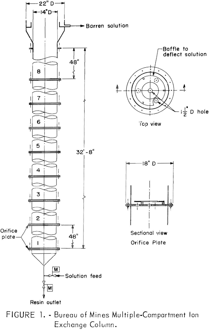
leaching solution. A schematic drawing of the column is shown in figure 1. The column used in the field tests is 14 inches in diameter (1 square foot) and consists of eight type 304 stainless steel sections, each 4 feet long and flanged to permit easy assembly. An 18-inch-long conical section is fitted to the bottom of the column, and a 24-inch- diameter section fitted with an internal peripheral overflow weir and launder is attached to the top of the column. The only moving parts are two ½-inch stainless steel ball valves at the base of the column, for controlling the input of solution and the withdrawal of resin. These valves are opened and closed by pneumatic actuators controlled by electric timers. Sampling cocks at the midpoint of each compartment permit withdrawal of solution and resin samples.
The novel feature of the column is its subdivision into vertical compartments, each separated by an orifice plate mounted between the flanges. The orifice plates are constructed of 0.5-inch-thick plastic and are perforated with four 1.5-inch-diameter holes, one in the center and three equally spaced on a circle of 6-inch radius. A deflector ring, 3 inches wide and ¼ inch thick, is mounted 0.75 inch above the radial holes. The hole area of each plate is 4.6 percent.
Mode of Operation
If a charge of closely sized resin in a column is subjected to a regulated upward flow of solution, the resin particles expand to a state of teeter
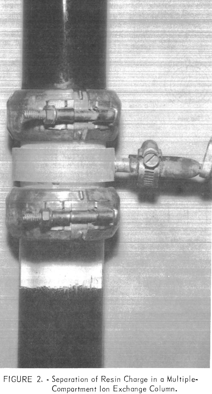
and slowly circulate and mix from top to bottom. Under these conditions, the column operates as a gently stirred reactor, and chemical equilibrium conditions stringently limit maximum utilization of the resin capacity. By assembling the column from short sections separated by orifice plates, vertical mixing of the resin is restricted to each compartment. As a result, the overall effect is of multiple-stage contact, which allows higher uranium recoveries and resin loadings at higher solution flow rates than are possible in a non-compartmented column of equivalent height. With the use of such orifice plates, each compartment is filled with a fluidized bed of resin whose volume is in equilibrium with that of the upward flowing solution. If the volume of resin in any compartment is initially in excess of the equilibrium volume, the excess resin moves up into the next compartment. If the volume of resin is less than the equilibrium volume, the compartment is not completely filled. Under either condition, resin cannot move downward until the solution flow rate is reduced until the solution velocity through the orifices is less than the terminal settling velocity of the resin.
Figure 2 shows the separation of resin in a glass laboratory column. The volume of resin in each compartment depends upon the solution flow rate, resin particle size, and the solution and resin densities. Figure 3 shows the effect of flow rate on the percent bed expansion using a minus 16-plus 20-mesh anion exchange resin loaded to about 48 grams of U3O8 per liter (3 pounds per
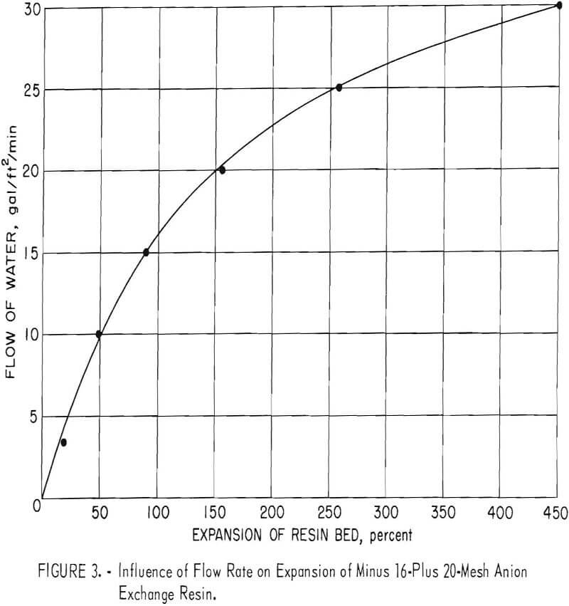
cubic foot). Because the uranium loading of the resin in the column increases from top to bottom, the percent bed expansion is slightly different in each section of the column.
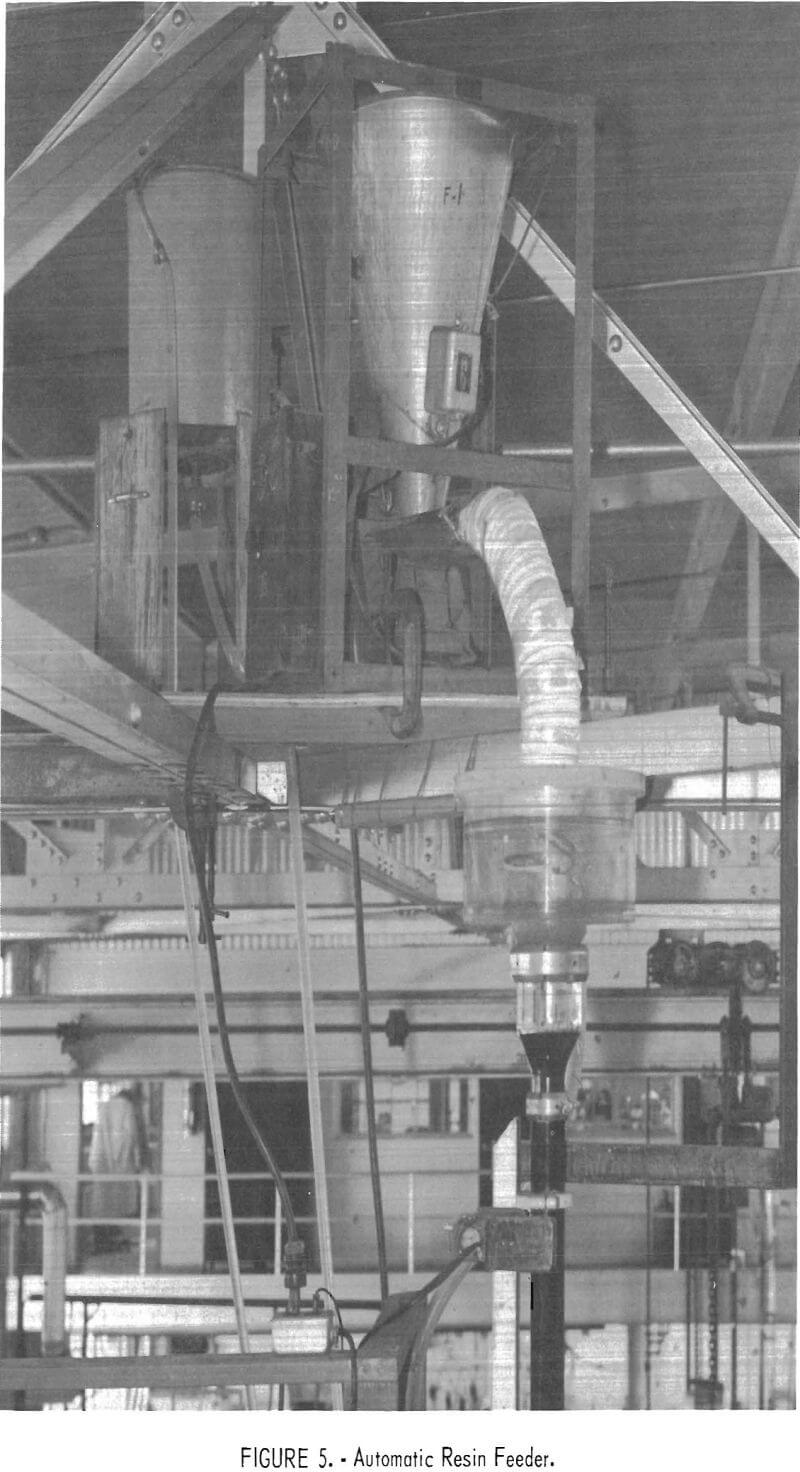
The column operates with a continuous flow of solution except for scheduled brief interruptions when the solution inlet valve is closed for a few seconds and a quantity of resin is withdrawn by opening the resin outlet valve. Simultaneously, equivalent volumes of resin move rapidly down the column from each compartment into the next compartment below. The resin outlet valve is then closed, the solution flow is resumed, and a like volume of stripped resin is charged into the top compartment. Charging of resin may be done manually or with an automatic feeder. The amount of resin moved per cycle depends upon the resin loading, the uranium throughput rate, and the percent uranium absorption. For example, if the resin at an assumed 100-percent absorption efficiency can be loaded to 5 pounds of U3O8 per cubic foot from a solution containing 5 pounds of U3O8 per 1,000 gallons, 1 cubic foot of resin must be withdrawn from the column and a like amount of eluted resin added to the column for every 1,000 gallons of solution processed. Automated solution and resin valves and an automatic resin feeder used with a laboratory column are shown in figures 4 and 5. The resin feeder is activated by an electric-eye level
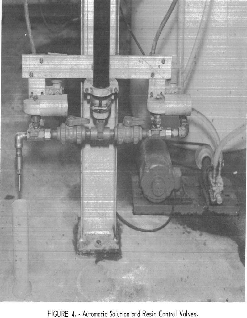
control to maintain a fixed resin level in the top section of the column. Other methods for feeding resin may also be employed.
Tests With Kerr-Mcgee Oil Industries
Tests at the Kerr-McGee uranium mill near Grants, N. Mex., were initiated in June 1968, and except for occasional interruptions were conducted on a three-shift basis until late September. During this period about 3 million gallons of mine water containing an average of 9 ppm U3O8 was processed with average recoveries in excess of 98 percent. The 14-inch-diameter, multiple-compartment column previously described was used, but because of height restrictions in the mine water treatment building, only five of the eight available compartments were installed. During the entire test period, loaded resin was automatically withdrawn from the column once a shift, and an equal
amount of eluted resin was added manually into the top of the column. Loaded resin was collected and eluted in batches of 1 to 2 cubic feet, in a tank with a screen bottom, by downward percolation of a 1.5 M NaCl solution containing 4 grams of NaHCO3 per liter. A new batch of Dow Chemical Co., Dowex 21K (minus 16 plus 20 mesh) resin was used in the tests.
Test Results
Preliminary tests established that excessive amounts of resin overflowed the column at flow rates in excess of 27 gallons per minute; hence the column was operated throughout the test period at 20 and 25 gallons per minute. At 20 gallons per minute, the average effluent contained less than 0.1 ppm U3O8, and the resin was loaded to 3.6 pounds of U3O8 per cubic foot (58 grams per liter). Uranium recovery was greater than 99 percent. Bed expansion was approximately 150 percent, and the resin inventory in the column was 8 cubic feet. Under these conditions, about 0.2 cubic foot of resin was withdrawn and a like amount was added every 8 hours. At 25 gallons per minute, it was necessary to increase the rate of resin withdrawal to 0.3 cubic foot per 8 hours to maintain high recovery efficiency. Under these conditions, the resin was loaded to an average of 2.9 pounds of U3O8 per cubic foot (46 grams per liter), and the effluent averaged 0.2 ppm U3O8 (98 percent recovery). The resin inventory in the column was approximately 6 cubic feet and bed expansion was 250 percent.
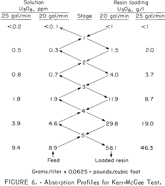
Samples of resin and solution were taken periodically from each compartment during the tests and analyzed for uranium. The results are presented in figure 6, which shows average operating pro-files when operating at flow rates of 20 and 25 gallons per minute.
Although flow rates and resin loading both affected overall recovery, the most important factor was the residual uranium concentration of the recycled resin. The resin was eluted in batches under less than ideal conditions, and an increase in the effluent assay invariably could be correlated with an increase in the uranium content of the stripped resin. Generally, stripped resin with a residual loading of no more than 0.06 pound of U3O8 per cubic foot (1 gram per liter) was adequately effective in absorbing uranium from this highly amenable mine water. This degree of stripping required abouc 60 gallons of fresh 1.5 M NaCl-0.05 M NaHCO3 eluting solution per cubic foot of resin and resulted in pregnant eluates containing 5 to 7 grams of U3O8 per liter. Higher grade solutions could have been obtained by recycling portions of the eluate.
The pregnant eluates produced during the test were comingled with pregnant eluates from the existing ion exchange plant and pumped to the uranium mill for uranium recovery. A few bench-scale tests, however, showed that the eluates can be treated directly to produce a specification-grade concentrate. For example, after acidifying with sulfuric acid and heating to expel CO2, the solution was neutralized to pH 7 with NH3 to precipitate uranium. This precipitate, after washing and drying at 110° C, assayed 87 percent U3O8 and met all current specifications for uranium concentrates.
Resin Losses
The carryover of resin with the column effluent was determined by passing the effluent over a 35-mesh screen and measuring the volume of accumulated resin once a week. The measured accumulation amounted to 12 cubic, centimeters per 1,000 gallons when the solution flow was 20 gallons per minute, and 42 cubic centimeters per 1,000 gallons at 25 gallons per minute. Based upon a feed solution grade of 10 ppm of U3O8 and a resin value of $53 per cubic foot, losses of these quantities of resin would be equivalent to 25 to 85 cents per pound of U3O8. Although the tests revealed that processing created only trace amounts of broken and worn resin finer than 35 mesh, the amount of resin over-flowing the column requires the use of a screen or a resin-settling tank to recover resin from the effluent.
Tests at United Nuclear Corp.
Tests at the United Nuclear Corp. plant near Grants, N. Mex., were conducted intermittently from April 1 to June 30, 1969. Resin used in these tests was minus 16-plus 20-mesh IRA-425 resin, made by Rohm and Haas Co. The mine waters available during the test period contained an average of 12 ppm U3O8. As originally installed, the column was set up with five compartments, but a sixth compartment was added for the last month of testing. Other operating procedures were approximately the same as at Kerr-McGee, with the residual U3O8 content of the stripped resin averaging less than 1 gram of U3O8 per liter.
The column was operated at 10 and 15 gallons per minute with five compartments and at 20 gallons per minute with six compartments. Absorption at 10 and 15 gallons per minute resulted in average effluent assays of about 0.25 ppm and a resin loading of 2.6 pounds U3O8 per cubic foot (42 grams per liter). Uranium recovery was 97.5 percent. The resin withdrawal and addition rates were 0.18 cubic foot per shift at the 10-gallon-per-minute flow and 0.28 cubic foot per shift at 15 gallons per minute. When the sixth compartment was added and the flow rate was raised to 20 gallons per minute, the effluent dropped to 0.1 ppm of U3O8 when loading the resin to 2.3 pounds of U3O8 per cubic foot
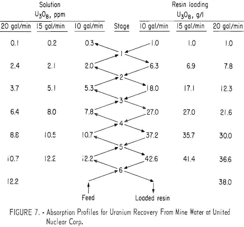
(38 grams per liter). Under these conditions, the resin withdrawal rate averaged 0.42 cubic foot per shift.
Profiles of the column under various operating conditions are shown in figure 7. Comparison with the profiles for the Kerr-McGee tests show slower rates of uranium absorption and lower resin loadings. These differences may result in part from the use of resins of different manufacture; but most likely, the differences in absorption are primarily the result of differences in the concentration of competing ions, such as Cl-, SO4=, and HCO3-, in the two mine waters.
Countercurrent Elution Studies
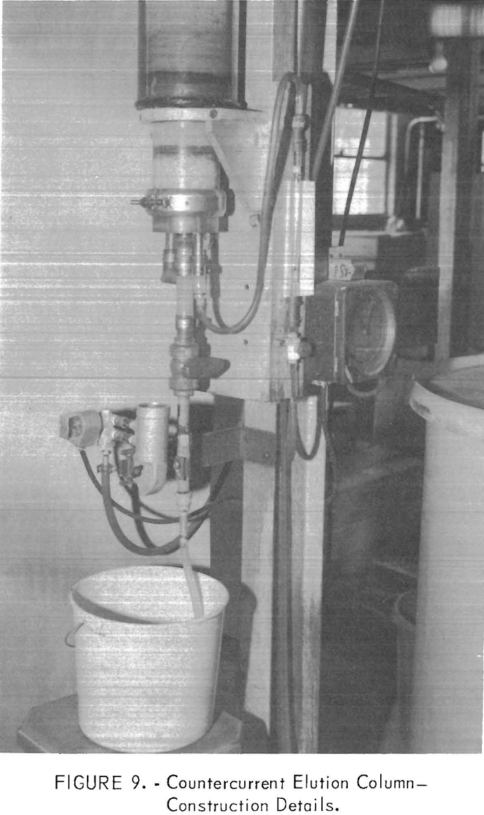
Countercurrent elution of uranium was studied at the Salt Lake City Metallurgy Research Center using loaded resin supplied by United Nuclear Corp. The elution tests were made in the 4-inch-diameter by 10-foot-high, continuous countercurrent elution column pictured in figure 8. Construction details are shown in figure 9.
The countercurrent elution column operates with an essentially packed resin bed. The eluting solution is introduced through a distributor bed of sized quartz fragments at the base of the column, and then moves upward through the resin bed and overflows a launder at the top. Resin loaded with uranium is introduced into the top of the column and moves downward in short slugs as the pneumatically operated resin outlet valve at the base of the
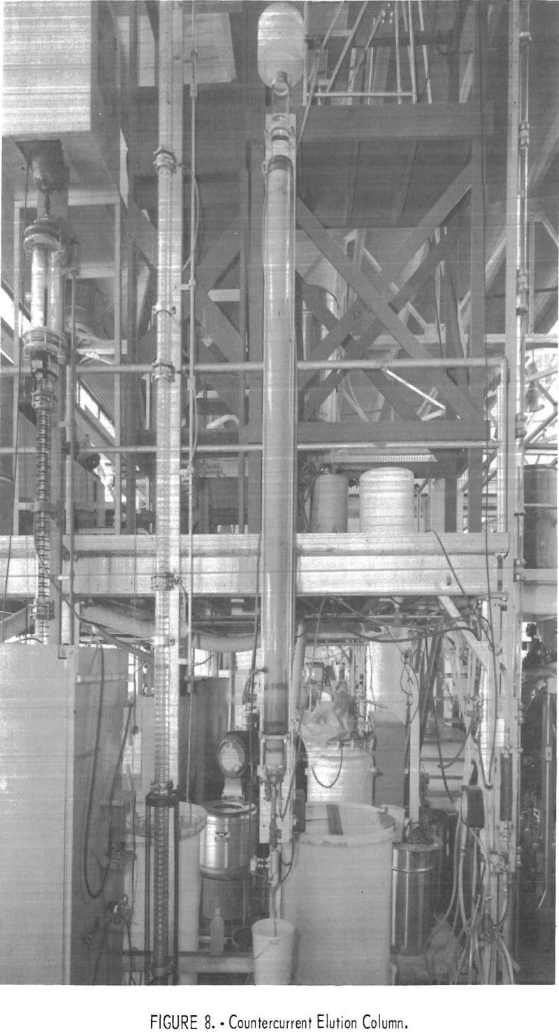
column is opened by an electric timer for 5 to 10 seconds at intervals of 2 to 3 minutes. Solution exiting with the stripped resin from the bottom of the column is separated by draining on a screen and returned to the eluate feed tank. An electric-eye controller actuates a vibrating feeder to maintain the top of the resin bed at any desired level.
Two requirements must be met to successfully operate the column:
- The density of the eluting solution introduced at the base of the column and the pregnant eluate overflowing the top must be less than that of the resin so that the resin will not float.
- The velocity of the upflowing solution must be slow enough to create a bed expansion of no more than 5 to 10 percent. With greater expansion, vertical mixing of the resin can occur with detriment to elution efficiency. For coarse bead anion exchange resins (minus 16 plus 20 mesh), the limiting solution flow is about 1 gallon per square foot per minute.
The resin elution studies were conducted on a three-shift basis, over a period of 5 days, using 25 cubic feet of resin borrowed from United Nuclear’s mine water treatment plant. The uranium loading was 2.4 pounds of U3O8 per cubic foot (39 grams of U3O8 per liter). The eluting solution used was 1.1 M NaCl plus 0.05 M NaHCO3, with a density of 1,040 grams per liter. Variables studied were resin bed depth, resin retention time, and the solution-to-resin ratio. Test results are summarized in table 1.
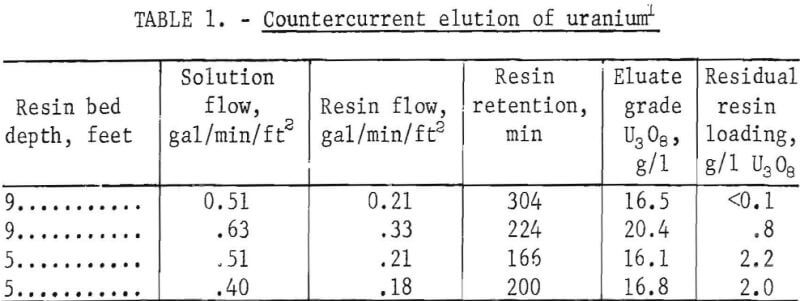
Efficient recovery of uranium from mine waters requires that the residual U3O8 loading of the elated and recycled resin be less than 1 gram of U3O8 per liter. The test data show that this requirement was met under the conditions shown for the first two tests. In the last two tests, the resin bed was shortened to permit an investigation of shorter resin retention times without exceeding desirable solution and resin flow rates. Under these conditions, residual resin loadings increased to 2-2.2 grams of U3O8 per liter. A brief period of operation at 50° C resulted in no substantial improvement in elution efficiencys but owing to a shortage of resin, the test was not long enough to be definitive.
A major objective of these tests was to elute the resin with a minimum volume of solution so as to produce a maximum eluate grade. The results show satisfactory elution using as little as 1.9 volumes of solution per volume of resin and a resin retention time of approximately 4 hours. Sufficient loaded resin was not available to allow a study of the effect of higher solution-to-resin ratios on the rate of elution. However, solution-to-resin ratios of about 3 should enable satisfactory resin elution with resin retention times of 3 hours or less. Use of a slightly stronger brine solution also should increase the rate of uranium elution. The limiting concentration would be about 1.5 M NaCl.
Comparison of Operating Results with Existing Plants
The pilot plant tests on uranium absorption and elution demonstrated significant advantages over existing plant practices. Equipment and resin requirements are greatly reduced, uranium recoveries are improved, and by reason of simple automation, manpower requirements are decreased.
In the existing mine water treatment plants, operating on absorption with two columns in series, solution flows range from 4 to 7 gallons per square foot per minute, and the resin inventory in each column is about 4 cubic feet per square foot of column area. Thus, the resin inventory is 1 to 2 cubic feet per gallon per minute of solution flow. By contrast, the pilot plant tests demonstrated that near complete uranium recovery can be achieved with a compartmented column at flows of 20 to 25 gallons per square foot per minute and with resin bed expansions of 150 to 250 percent. Under these conditions, the resin inventory in a six-compartment column would be 7 to 10 cubic feet per square foot, or only 0.3 to 0.5 cubic foot per gallon per minute of solution flow.
Even greater reductions in resin and ion exchange equipment requirements would accrue from the use of a continuous elution column in conjunction with a compartmented absorption column. This can be illustrated by the following hypothetical examples which assume treatment of 1,000 gallons per minute of mine water from which 10 ppm (0.083 pound) of U3O8 is recovered at a resin loading of 3 pounds per cubic foot (48 grams per liter). The loading rate is 5 pounds of U3O8 or 1.7 cubic feet of resin per hour. An existing-type ion exchange plant operating at an assumed flow of 7 gallons per square foot per minute would require two columns operating in series. Each column would be about 14 feet in diameter with an area of 143 square feet and would contain 572 cubic feet of resin. Each column, therefore, has a capacity of 1,716 pounds of U3O8 and would be onstream for 342 hours. Each column would be in the trailing position for half this period and in the leading position for the remaining time. When the resin in the leading column is fully loaded, it is hydraulically moved to an elution column. Resin in the trailing column is then transferred to the leading column, and the now empty trailing column is filled with 572 cubic feet of eluted resin. The flow of mine water then is resumed.
Elution of the charge of loaded resin requires about 10 hours, and the resin is then idle for 161 hours, until another column is ready for elution. Thus, at any given time, one-third of the resin inventory of 1,716 cubic feet is not being used. Greater utilization of the resin would be made possible by using several sets of smaller columns on absorption, so that the elution cycles could be staggered, but this would require more equipment. Alternatively, only one column could be operated on absorption during the 10 hours that a charge of resin is being eluted, but this would reduce recovery and production.
In contrast, at an assumed flow rate of 20 gallons per square foot per minute, a compartmented column 8 feet in diameter (50 square feet) and containing six compartments, each 4 feet deep, would suffice for treating a flow of 1,000 gallons per minute. The resin bed expansion would be 150 percent, and the resin inventory 480 cubic feet. Elution of the resin would be conducted in a continuous elution column at a resin flow of 1.7 cubic feet per hour and a resin retention time of 4 hours. This would require an elution column 1 foot in diameter and 12 feet high with a resin inventory of only 7 cubic feet. The total resin inventory in both the absorption and elution circuits would therefore be only 487 cubic feet or 30 percent of that required using conventional for exchange techniques. The cost of equipment would also be significantly reduced Finally, because both the loading and elution operations would be completely automated, labor requirements would be lower.
Hydraulic Testing of a Six-Foot-Diameter Compartmented Column
The success experienced with the 14-inch-diameter, compartmented column prompted inquiries regarding problems of scale-up and particularly the design of orifice plates for large-diameter columns. Accordingly, the column shown in figure 10 was constructed to allow hydraulic tests with water. The column was fabricated from 12-gage mild steel and consists of two 6-foot-diameter by
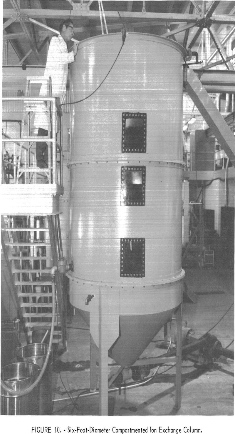
4-foot-deep sections plus a 45° conical bottom compartment having a 1-foot-high straight wall. Each section was fitted with 2-inch rolled flanges to permit easy assembly and installation of orifice plates. Introduction of water and withdrawal of resin was controlled by two 4-inch valves at the apex of the cone. Initially, water exiting the top compartment overflowed through a 6- by 10-inch opening and chute to a recycle tank. A 4-inch-wide internal launder was later installed to produce a more uniform overflow. Water feed to the column was pumped from a recycle tank into the base of the cone. An orifice-type flowmeter, mounted in the pump discharge line, was used to measure flow rates. Clear plastic windows and internal lights allowed observation of the resin when the column was in operation.
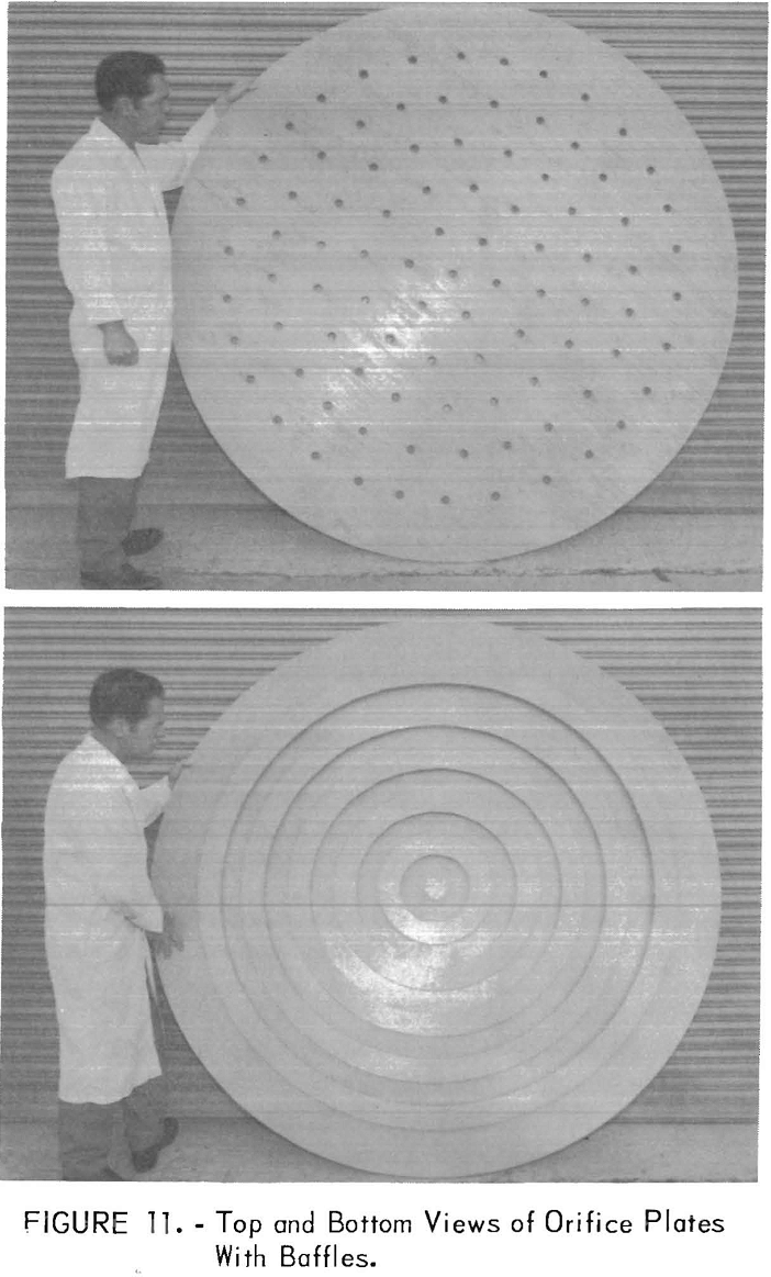
The orifice plates were constructed of ¾-inch plywood and were bolted between the flanges. A thick layer of silicone rubber sealant gave a watertight seal. Orifice plates with varying hole spacings and with hole areas of 1.6 to 6 percent were tested. These included plates with ½-inch- to 1-1/16-inch-diameter holes on 4-inch centers and plates with 1-inch-diameter holes, 6 inches apart on circles every 6 inches from the center of the plate. The use of deflector rings mounted in a circle above the holes to deflect the upflowing water was also studied. Top and bottom views of this type of plate are shown in figure 11.
The column was charged with 70 cubic feet of resin and was tested at water flows up to 550 gallons per minute (20 gallons per square foot per minute), which was the maximum pumping capacity. Essentially, no differences were noted in the fluidization of the resin bed between one type of plate and another. In all cases, the resin bed was readily fluidized from the compacted state and responded to variations in flow rate in a manner identical to that observed with smaller columns. In addition, when the water flow was interrupted and the resin withdrawal valve was opened, resin moved readily downward through the orifice plates, but the movement was sluggish for the plate with ½-inch holes on 4-inch centers. The open area of this plate was only 1.4 percent. An open area of 5 to 6 percent was entirely satisfactory and can be achieved by drilling 1 inch holes on 4 inch centers. The use of deflector baffles mounted above the holes was not beneficial.
The principal deficiency in the design was the use of a conical bottom compartment. The large capacity of this compartment led to excessive volumes of water being withdrawn before the appearance of resin, when the solution valve was closed and the resin valve was opened. This resulted in an excessive downward movement of resin between compartments and a delay in reaching hydraulic equilibrium when the water flow was resumed. The difficulty was corrected by installing a 2-inch valve in the side of the column to permit withdrawal of resin just above the top surface of the bottom orifice plate.
Resin withdrawal through this valve was instantaneous, and the measured rate was 2.5 cubic feet per minute. Higher withdrawal rates would be made possible by using a larger valve, or preferably, by withdrawing resin from multiple outlets connected to a manifold of adequate size.
By eliminating the conical bottom section, the overall design is simplified, but a means must be provided to introduce solution uniformly below the bottom orifice plate. Construction of a dished bottom compartment about 2 feet deep, fitted with a manifold to allow the peripheral introduction of solution at four or more points, might provide a solution.
Summary and Conclusions
Tests were conducted to investigate recovery of uranium from mine waters, available in the Ambrosia Lake district of New Mexico, using countercurrent and substantially continuous ion exchange techniques developed by the Bureau of Mines. In these tests, approximately 5 million gallons of mine water containing an average of 10 ppm U3O8 was processed through a 14-inch-diameter, compartmented ion exchange absorption column. Uranium recoveries averaged in excess of 98 percent, at resin loadings of 2.3 to 3.6 pounds of U3O8 per cubic foot and at solution flows up to 25 gallons per minute. Tests also were conducted to study elution of the loaded resin in a continuous elution column. Loaded resin was eluted to residual loadings of less than 1 gram of U3O8 per liter with only 2 volumes of solution per volume of resin and a resin retention time of less than 4 hours. Compared with existing ion exchange practices for recovering uranium from mine waters in the Ambrosia Lake district of New Mexico, use of these improved ion exchange techniques would reduce resin inventory requirements by at least 70 percent and substantially reduce equipment and labor costs. Hydraulic tests with a 6-foot-diameter, compartmented column indicated that the construction and operation of large-diameter columns would present no difficulties.
