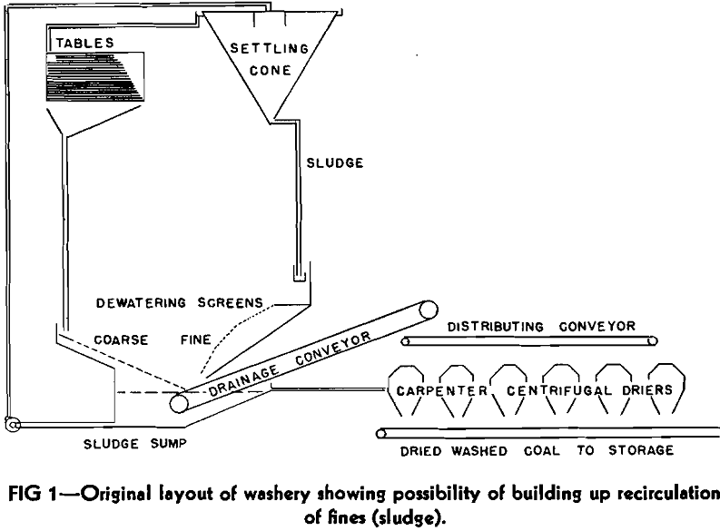
One of the chief difficulties with which the operator of a coal washing plant has been forced to contend is the handling of the very fine coal. First he has the problem of separating the fine coal from washery water. This is usually accomplished by the use of settling cones or Dorr thickeners: in either event the separated fine coal contains a high amount (40 to 80 pct) of water and, somewhat loosely, dependent upon the size of the coal particles present, may be known as sludge or slurry. His second problem is the satisfactory further dewatering of such separated sludge and/or slurry.
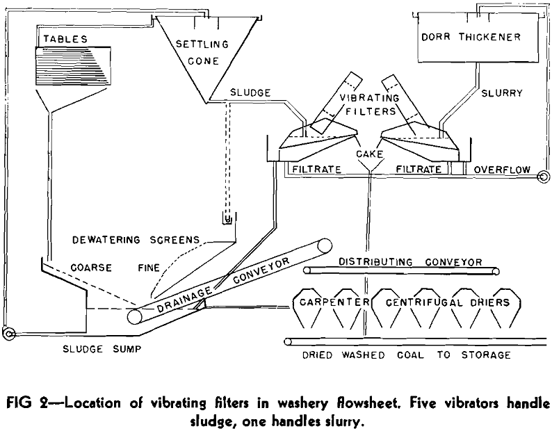
In order to regain the loss in active throughput which had been caused by this circulating load, an installation of six vibrating filters was made during the year of 1936. This resulted in an increase in normal tonnage of washed coal from 1430 to 1750 tons per 8-hr shift, a gain of slightly over 22 pct. This increase in throughput has made a very substantial decrease in the “conversion cost” per ton of washed coal. Since the vibrators were installed, we have gained about 2,000,000 tons in production, compared to what would have been produced in the same number of shifts at the former rate. Putting it in slightly different form, we have saved in the past 12 yr the cost of 1400 operating shifts in the washery.
The Filter Mechanism
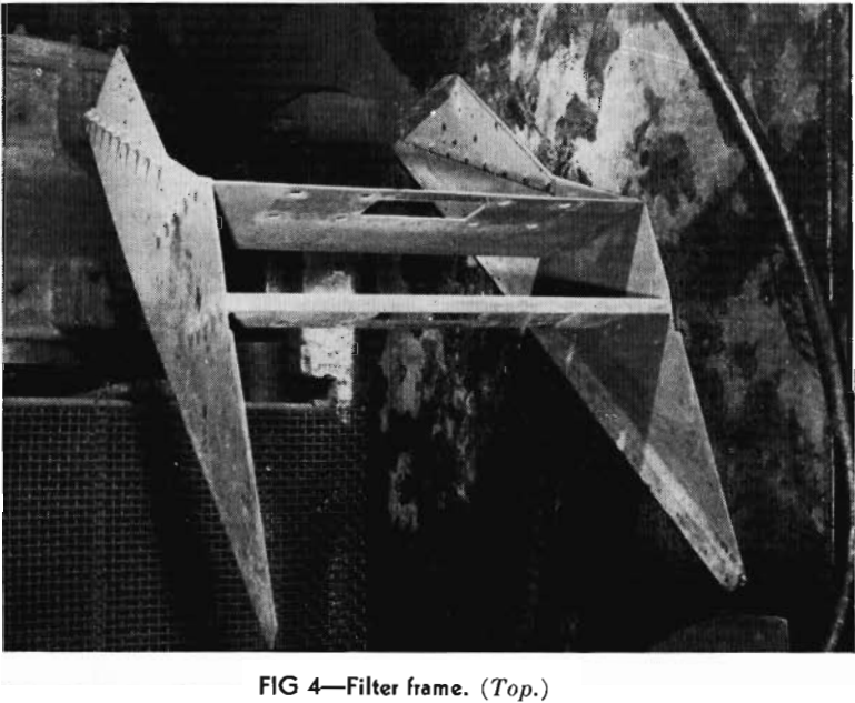
We now come to the details of construction of the vibrating filter and these are shown in Fig 4 to 7, inclusive. It will be noted that the filter proper consists of three main parts:
- A frame of welded and riveted construction (Fig 4) to support the screen assembly.
- A screen assembly (Fig 5 and 6) consisting of a foundation, a backing-up plate and a screen wire cloth.
- An electrical vibrating unit.
The frame proper needs little additional description, beyond the fact that it is made up of 3/16-in. steel plate, with careful attention being paid to the welding to ensure against failure due to the heavy vibration to which the entire filter is subjected. The frame is supported, or hung, directly from the vibrating unit, this being attached to the frame by the cross members which are securely bolted to the “bull head” of the vibrator.
The Filter in Action
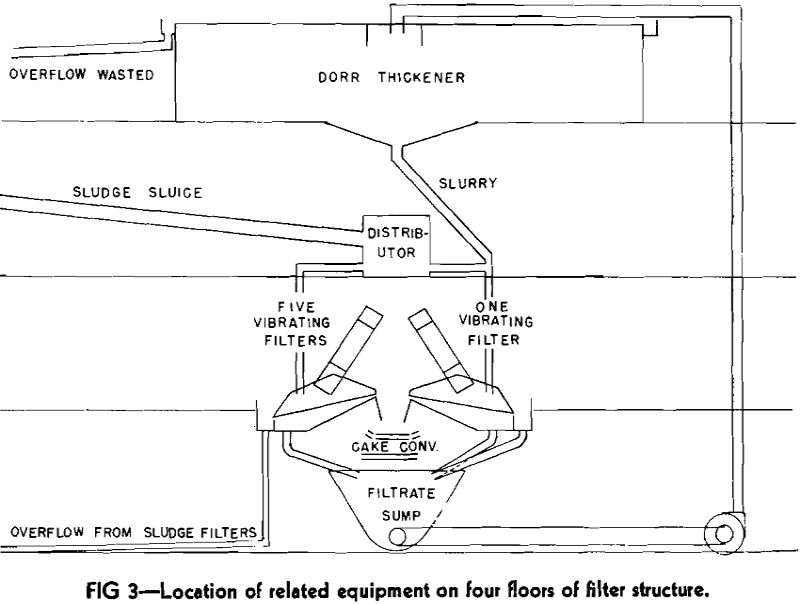
When vibration is applied to the machine, things begin to happen. The sludge settles to the bottom of the pool, the vibrating action packs the sludge and squeezes out water, the compacted cake then starts moving up the screen, due to the differential stroke employed, and is compacted further in the process, more and more of the excess water being squeezed out. In the final stage, the cake moves out of the pool, dewatering is completed, and the “dry” cake is discharged, a view from the discharge end. This cake has had its water content reduced to within 2 or 3 pct of that which would be obtained with a vacuum filter. The cake at point of discharge is dry enough and compact enough so that when it extends some distance beyond the end of the screen it will break off sharply because of its weight.
The water separated from the sludge is split between overflow and filtrate. Ideal operation would, of course, involve no overflow; but this requires the use of a feed which is difficult to obtain and difficult to handle once it is obtained. We would prefer to operate with a feed containing between 50 and 60 pct solids. Such a feed would eliminate the necessity for overflow and would almost double the tonnage with the same dewatering effect as we now obtain with feeds containing 33 to 45 pct solids. The greater part of the filtrate goes through the lower end of the screen, where there is a considerable depth of pool, and where compaction of the cake has not been fully accomplished.
Capacity of the Machine
As has been pointed out above, the capacity of the machine is limited by the amount of water in the sludge. It is also affected by the fineness of the solids. The area of the screening surface and the size of openings in the screen cloth are fairly well established and can be modified only within rather narrow limits. The maximum size of screen which we have been able to operate satisfactorily is 3 ft wide by 6 ft long. Above this size the extra weight of material which would be necessary to ensure absolute rigidity is so great that the useful load is reduced. With the 3 by 6 ft screen, and with a feed containing 40 pct solids, a cake production of 10 tons per hour per unit is regularly secured. If the feed is prethickened to 50 pct solids, the capacity is increased to 15 tons and with a feed pre-thickened to 60 pct solids, to 20 tons per hour. Since the cake with a normal sludge feed (practically all minus 6 mesh) will contain 20 to 24 pct water, the above capacity figures must be reduced by about 22 pct or to 7.8, 11.7 and 15.6 tons of dry fine coal per hour.
Dewatering Effect
The amount of dried sludge cake delivered by the unit has little, if any, effect upon the moisture content of the cake, and, at an operating rate of 20 tons cake per hour, cake moisture has been recorded lower than with 10 tons output. However, the particle size of the material present in the sludge or slurry does have an important bearing on the moisture content of the final product.
