From the old-fashioned “ grab-sample ” to the modern timing- device, which takes a machine-sample with mathematical precision, there is a wide gap, which was only crossed by many years of toil and unremitting endeavor. Even to-day, notwithstanding the advancement in the art, “ grab-sampling ” is still practiced—sometimes to afford the unscrupulous mine-promoter a basis for fairy-tales with which to entrap the too-gullible investor, and often by milling and smelting companies to determine the amount of moisture in custom-ores. The latter practice is almost as reprehensible as the former, and it causes more trouble and ill-feeling between seller and buyer than all other factors put together. No reputable concern to-day would think of attempting to determine by grab-sampling the amount of gold, silver, lead, or copper contained in an ore, and yet many buyers expect the miner to accept the results of grab-sampling in the determination of the amount of water contained in the ore, forgetting that accurate results are just as necessary here as in the determination of the metals, because the result determines the percentage of weight of the ore which shall be excluded and considered to have no value whatever.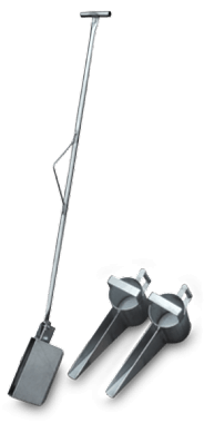
Samples for the determination of moisture should be taken with as great care as samples for the determination of metallic content, and in order to avoid the extra expense of a separate operation moisture samples should be taken from the sample-safe. As the sample reaches the sample-bin in a smaller stream and by a more circuitous route than the “ reject” travels in its path to the outgoing car, it loses more moisture en route, and a constant should be added to compensate for this difference. Carefully-conducted experiments have shown that the difference in loss of moisture between the two routes does not exceed 10 per cent, in summer and 7 per cent, in winter. For instance, a lot of ore shipped during the summer months, in which the machine-sample showed 5 per cent, of moisture, would have an actual moisture-content of 5.5 per cent. Grab-sampling by an interested party, at its best, is only a prejudiced conjecture, while at its worst it gives rise to the most unscrupulous practices with which the ore-producer and the mining-investor have to deal.
Shovel-sampling, another archaic method which is still used in some localities, consists in throwing out from the car or wagon every third, fifth, or tenth shovelful for a sample. As the portion of the pile from which the sample is taken is entirely at the discretion of the operator, the process would be more properly named fifth-shovel selection than fifth-shovel sampling. Between the conscientious workman who endeavors to be absolutely upright, and often becomes, as the Scotchman said, “ more than plumb,” and the scheming laborer who, desiring to make his “job solid,” takes a “safe sample,” there is little room for truth or accuracy in this method, and the sooner it is consigned to oblivion the better for every one concerned.
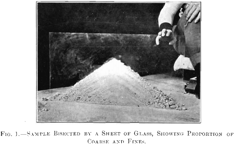
Thirty years ago Cornish quartering was the almost universal method of sampling in use, and it is still employed to a considerable extent in cutting-down machine samplers and in mine-examinations where no machinery can be had. When properly carried on with skill, care, and common honesty, fairly-good results may be obtained by quartering, but between the possibility of accidental mistakes and the opportunities which it affords for skillful and unscrupulous operators to manipulate the sample, it has fallen almost into disuse, and should have been completely abandoned long ago. The inherent defect of this system lies in the fact that piling a lot of ore in the form of a cone does not mix it, as the advocates of this system claim. Dropping shovelful after shovelful of ore on top of a cone, instead of building up a homogeneous pile, actually produces a very perceptible sorting-action, whereby the fines build up where they fall on the center of the cone and the coarser particles roll outward and down the sides. This is illustrated in Fig. 1, which is a half-tone from a photograph of a cone built up in actual sampling-practice and bisected by a sheet of glass. This section shows conclusively the great difference in the relative proportion of coarse and fines between the outer and
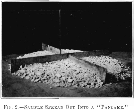
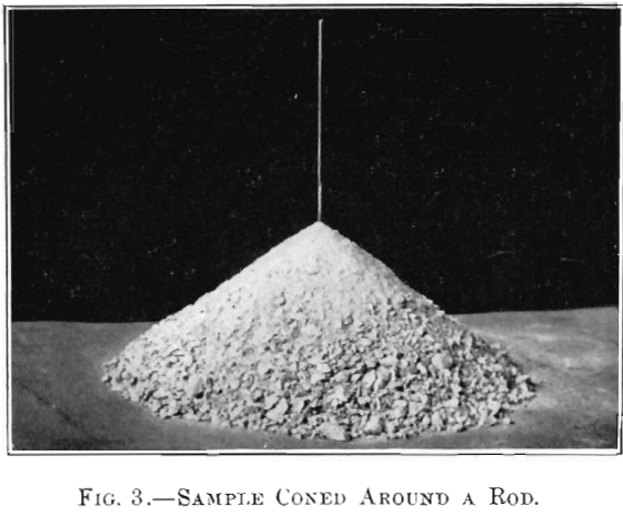
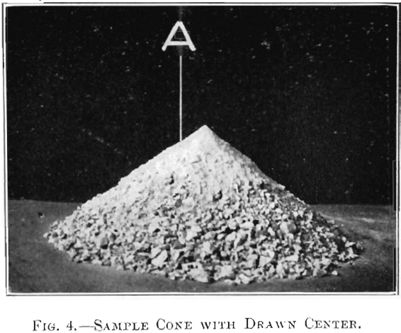
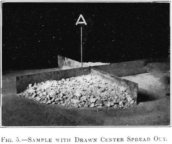
inner portions of the cone, and also makes it perfectly clear that even after the cone has been spread out into a “ pancake,” as shown in Fig. 2, the fines in the lower portion of the cone will be entirely undisturbed. The most uniform and best results are obtained by coning around a rod, as shown in Fig. 3. By this means the center of the cone is maintained in a vertical line, and if care is taken in working down the cone to a “ pancake,” as shown in Fig. 2, and separating the quarters by steel blades, so that there is no difference between the quadrants taken for the sample and those thrown into the reject, the results give a fair approximation of the truth, though it is not possible to duplicate results very closely by this method, even at its best.
It would take altogether too much space here to enumerate the different schemes which unprincipled operators have introduced into this method for the purpose of “throwing” the sample, and description of one of them will suffice.
The most ingenious of these plans, and one which is so difficult to detect that it can be carried on directly under the eyes of a skilled observer without detection, is what is known as “ drawing the center.” The cone is started on the floor, as shown in Fig. 3, but without any rod to determine the position of the center. The operator in charge of the work, in dropping his shovelfuls of ore on the top of the cone, does it in such a manner as to draw the center of the cone imperceptibly in a certain direction, so that by the time the entire sample is piled and ready for spreading, the apex of the cone, shown in Fig. 4, is several inches, we will say, to the SE. of the original center, which is indicated by the perpendicular line, A. The ore may now be spread as usual with shovels or with a board, and cut and marked into quadrants by steel blades in alignment with the four points of the compass, as shown in Fig. 5, where the rod, A, indicates the original center of the cone, which, of course, has been entirely undisturbed by the mixing and spreading of the upper portion. By rejecting the NW. and SE. quarters an excess ratio of the fines is eliminated, and since these are generally the richest ore, the metallic contents of the two retained quadrants, shown in Fig. 5, will be somewhat less than the average of the original pile. Suppose a 2,000-lb. lot is to be reduced to 62.5 lb., it would mean that the “quartering” (really halving) would have to be repeated five times; and if at each stage the sample taken represented 98 per cent, of the actual value of the cone, the final sample would only give 90.3 per cent, of the true value of the cone, as shown in the following tabulation :

The shifting of the cone-center is easily carried out; in fact it is difficult to avoid it unless some definite means of preventing it is adopted. Fig. 1 shows very clearly the structure of a cone with a “ drawn ” center, and in this instance the effect was entirely unintentional.
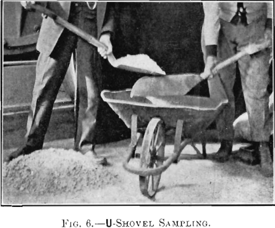
The irregularities in the results obtained by Cornish sampling, together with the cost of operation and the amount of room required, soon brought about what is known as “ split-shovel ” sampling, in which the ore is thrown from a broad shovel, handled by one operator, upon a narrow U-shaped shovel, held by another workman, usually directly over a car or wheelbarrow, as shown in Fig. 6. This method, while it requires two men to do what normally appeared to be the work of one, was cheaper than Cornish quartering, but it proved no great improvement over the latter in point of accuracy, since carelessness in almost any direction interferes seriously with the results.
The earliest attempts at mechanical sampling were made by subdividing a falling stream of ore; a process based on the supposition that an ore-stream could be mixed so as to be perfectly homogeneous. Both analysis and experience have shown that this ideal condition is impossible, and mechanical devices for taking a portion of the ore-stream all of the time have been almost entirely displaced by machines designed to take all of the ore-stream for a portion of the time. It is not practicable to produce a stream of ore which shall be continuous in value through every part of its length, any more than it is possible to produce a stream of ore that is constant in value throughout its width; but by taking a small sample entirely across a falling stream at very short intervals it is found that, while no single cut would give an exact representation of the composition of the entire lot, the average of thousands of these small samples is so nearly correct that results can be duplicated within very narrow margins, or, in other words, that individual errors are balanced. This was not the case with the devices used for taking a portion of the stream all the time, since the errors due to feed, inclination of spouts, or wear on the bottoms of the spouts are constant, and do not vary during the time the samples are being taken.
Almost coincidental with the discovery of the fact that accurate samples could be obtained by taking all of the stream for a portion of the time, came a very considerable improvement in rock-crushing machinery, so that the modern engineer has a much better opportunity to construct a satisfactory plant than the builder had 20 or 30 years ago. Not only are the rock- breakers and rolls of to-day greatly improved in design, but the manufacturers have availed themselves of modern cheap steel to give all parts an excess of strength over any possible strain, while the use of alloy-steels for the wearing-surfaces permits the machines to be kept in much better repair, and requires fewer stoppages for renewals. For sampling-work, crushers and rolls can now be had which are almost as well made as the ordinary steam-engine, and so designed as to give complete accessibility for renewals and for cleaning.
Gyratory breakers of the Gates type have the advantage of delivering a very uniform product, and in crushing ores that are hard and dry this type forms by all odds the best initial crushing-machine; but with ores that carry wet clay, slate, or other substances which will “pack,” it is necessary to use a swinging-jaw crusher, preferably of the Blake type. Rock-breakers may be set to crush to any desired fineness, but it has been found that too great a reduction in the size of the product very materially reduces the capacity. In large crushers it is not usually advantageous to attempt to crush below 2 in. in size.
First-class rolls are now always belt-driven, which eliminates the noise and danger attending the operation of the old-fashioned trains of gears. The best practice in roll-crushing is to crush not smaller than half the diameter of the particles fed to any given machine. This rule gives approximately the maximum crushing-capacity with the minimum production of fines and the lowest expenditure for power and metal. Rolls require a steady feed, and one which is uniform across the entire width of the shell; consequently, nearly all modern rolls are equipped with some feeding-device. In sampling-mills the shaking-tray is generally used on account of the ease with which the rate of feed can be inspected, and the great facility with which such feeders can be cleaned after each lot of ore has been run.
For fine-grinding machines, the coffee-mill type still successfully holds its own against most of the newer devices, although the modern sample-grinder is much heavier, better built, and more easily cleaned than its predecessors.
The first mechanical samplers were imitations of Cornish quartering, the ” whistle-pipe ” being the most common type. With ore finely crushed, fairly dry, well mixed, and entirely free from strings and rags, and with the dividers new and exactly centering the pipe, fairly good results could be obtained by this method; but as these conditions never existed in practice, and as the edges of the cutters wore rapidly, thereby moving the dividing-line back from the center, this form of sampling- machine was soon discarded, and I believe has now fallen into absolute disuse.
Following the whistle-pipe sampler came the various forms of mechanical split-shovels; but as there was no place in a spout, no matter bow wide or carefully built, where a single U-shaped spout could be placed to take a sample which would represent the entire width of the stream, this form also was soon discarded.
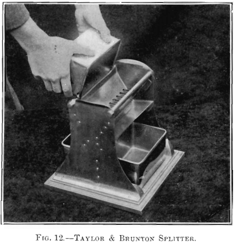
More recently this splitter has been revived by an adaptation of the ordinary hand-operated sample splitter (see Fig. 12), in which numerous small spouts are so arranged across the entire width of a larger one that the main ore-stream is divided into a great number of smaller ones, the even numbers being deflected to the right and the odd numbers to the left. This plan works very well on the first division, but as it effects a reduction of only 50 per cent, in the volume, the operation must be carried further, and the streamlets forming the sample centered into a broad stream, which, in turn, passes over another set of splitters, the operation being repeated as often as necessary to reduce the sample to the desired size. It has been found, however, that the mixture of the streamlets after their union is far from perfect, and that there is a considerable difference in the amounts of coarse and fines taken by the sample side of the second cutter, depending on its position relative to the cutter above. If the sample-compartments in the second cutter are directly below the sample-compartments in the overlying splitter, they receive the centers of the streamlets, while the “spread” passes into the reject, and the sample at each step in the bank of cutters receives an amount of fines slightly in excess of the average, thereby seriously affecting the value of the sample, provided there is, as is usually the case, a difference between the metallic contents of the coarse and the fines. Conversely, when each cutter in the bank is placed so as to take the “spread” from the cutter above it, the sample will have less than its due proportion of fines. This disadvantage could be obviated by placing a shaking-tray between each set of dividers, or perhaps even better, by moving one divider horizontally across the other, so that each set of cutters would take all parts of the streams from the cutters above them. This arrangement, however, would require considerable head-room, and give a machine which would make a large amount of dust—a feature which is always objectionable in a sample- room.
The latest types of samplers are designed to overcome the difficulties just described, and are usually known as “time-sampling machines,” from the fact that they deflect the entire stream into the sample-compartment for a varying portion of the time, depending on the percentage of sample required. Treating the falling stream of ore as a ribbon, they cut sample-sections directly across its entire width, these portions varying in shape and size with the mechanism employed. Of the many, types that have been invented and patented, only three have come into general use, and Fig. 7 show’s the shapes of the sample-sections taken by these three machines.
A represents a sample cut from the falling stream of ore by the Charles Snyder 20-per cent, sampler, with four radial intake-spouts, making 7.5 rev. (or 30 samples) per minute; delivery-spout 5 by 25 in. (This sampler is not to be confounded with the Snyder sampler.) It will be seen, on this machine, that an attempt has been made to combine the old-fashioned continuous sample with the time-sampling system by arranging the delivery-pipe and intake-spouts so that as one intake-spout passes out of the stream another enters it on the opposite side.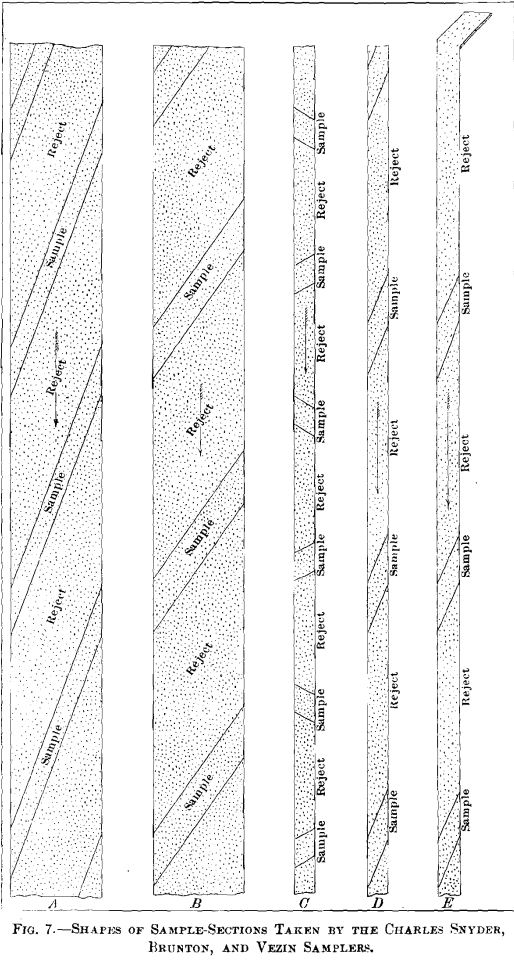
B represents a Charles Snyder 20-per cent, sampler, with two radial intake-spouts, taking 15 samples per minute; delivery-spout 5 by 25 in. This machine does not take a continuous sample, but has the advantage that the intake-spouts, for a given percentage of sample, have double the width, and are therefore much less liable to throttle or choke; at the same time there is no reason why the sample should not be as accurate as that taken with the other type of Charles Snyder sampler.
C represents the sample taken by the Brunton 20-per cent, sampler, taking 54 samples per minute; delivery-spout 5.75 by 5.75 in., cutting-edges parallel.
D represents the sample from a Vezin 20-per cent, sampler with two radial intake-spouts, taking 30 samples per minute; delivery-spout 6 by 6 inches.
E shows the sample taken by a modified form of sector-sampler, which, often through accident and sometimes by design, has come into too-general use.
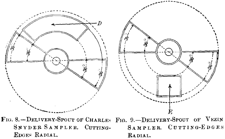
Both the Charles Snyder and the Vezin samplers have sector intake-spouts revolving on a vertical axis, the only difference betwreen the machines being that the delivery-spout in the Snyder sampler is an annular quadrant, D, in Fig. 8, while the Vezin delivery-pipe is either square or rectangular, E, in Fig. 9. In order to take a correct sample the cutting-edges of the sector intake-spouts on both of these machines must be exactly radial, as shown in Figs. 8 and 9, otherwise they will include more degrees of arc at one part than at another; and consequently the percentage of sample taken from all parts of the delivery-pipe will not be the same, as is shown by Fig. 10, in which the cutting-edges are not radial to the center of rotation. This, while by no means an exaggerated example of this form of distortion, shows a 74/360, or 20.8-per cent., sample taken on one side of the ore-stream and 88/360, or 24.4 per cent., on the other. If the falling stream of ore were perfectly homogeneous this arrangement would not make any difference, but it is well known that the ore-stream is not uniform, especially in an inclined spout, in which the coarse, rapidly-moving particles go bounding along on the top, while the finer portions hug the bottom, and on leaving the spout the coarse is projected a considerable distance and the fines drop almost vertically, which gives a sorted falling stream, with coarse on one side and fines on the other. With a tangential feed to a sector intake this sorting-action does not seriously affect the sample if the delivery-spout is perfectly level and free from ridges which would deflect the particles across the stream ; but when a radial feed is used, as shown in Fig. 9, and the intake sample-
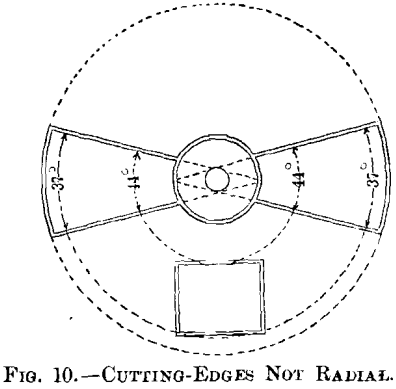
spout edges are not radial, as shown in Fig. 10, it will readily be seen that a larger proportion of coarse than of fines is taken into the sample.
Since the cutting-edges of this class of samplers, Fig. 11, are necessarily maintained in a horizontal position, they are very liable to become overhung with strings, burnt fuse, and
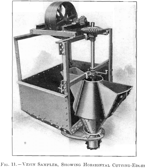
drill-rags, which the mill attendants often endeavor to remove by pounding the sides of the spout while the machine is in motion, thereby distorting the form of the intake-spout very considerably from a true sector, and rendering it impossible to obtain a correct sample unless the delivery-stream is perfectly homogeneous, which is never the case. The great length of the radial edges of the sector intake-spout renders them, of course, peculiarly susceptible to be thrown out of alignment, and manufacturers of this class of machines should do something to shorten up the length of the radial edges, or stiffen them to prevent accidental distortion. At first sight it might be thought that this could be accomplished by reducing the size of the sector, but experience has shown that the width of any spout, delivery, or intake should be something more than three times the greatest diameter of the coarsest particle passing through it; otherwise, a bridging effect occurs which affects the flow and often chokes up the spout. It is, therefore, good practice to make the width of the feed- and intake-spouts four times the diameter of the coarsest particles passing through them.
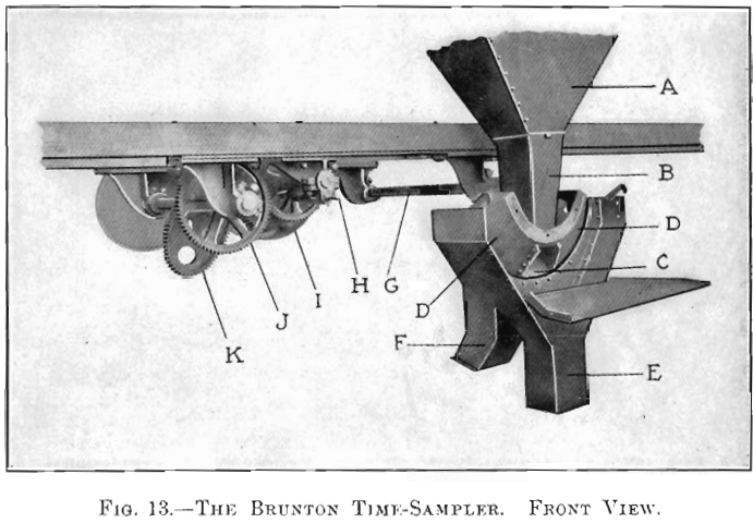
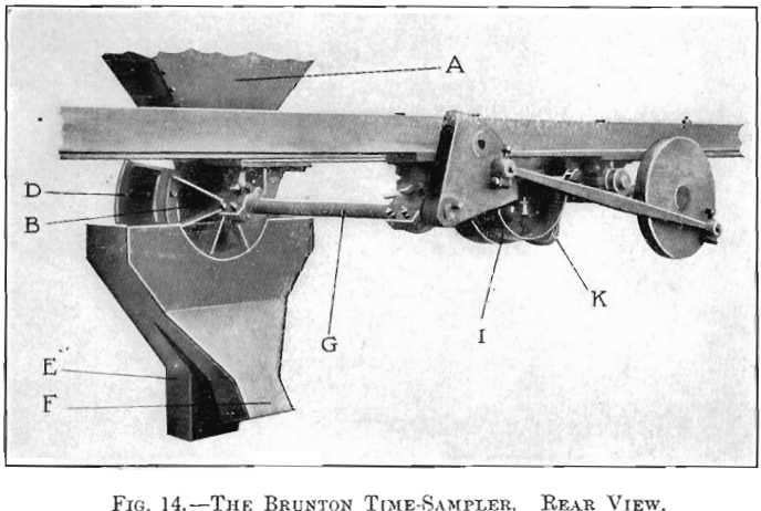
The Brunton time-sampler oscillates in a vertical plane through an arc of 120° instead of revolving in a horizontal plane like the sector-intake machines, an arrangement which permits the use of a rectangular intake-spout with cutting-edges so short that accidental distortion is impossible, while the tilting of the cutters at the end of the swing materially assists in dislodging any rags or strings which may have fallen on the cutting-edges. This construction requires less head-room than any other system, which effects a great saving in the cost of mill-construction, since it not only reduces the necessary height of the building but shortens all spouts and conveyors. The design of this machine cannot be very clearly shown in a linear drawing, but may be readily understood from Fig. 13, which is a front view of the sampler, having the housing open for cleaning. The various parts are explained as follows : A, receiving-hopper from crusher or rolls; B, delivery-spout; C, sample-intake; DD, “reject” divisions; E, housing-spout leading to the sample-bin ; F, reject-spout leading to the shipping-bins; G, oscillator-shaft; H, gear-shift; I, driving-pulley; J, spur-gear; K, eccentric gear. Ordinarily the machine is driven by the spur-gear, J, in which case a 20-per cent, sample is taken, but when a 5-per cent, sample is required the gear is slipped along the shaft, disengaging the spur-gear and bringing the eccentric gear, K, into play. Another advantage in the use of this machine is that, as the discharge of the ore from the sampler is assisted by centrifugal force instead of being retarded thereby, as is the case with all sector machines, it can be run at a much higher rate of speed, thereby increasing the number of samples per minute. This arrangement insures greater accuracy, since the more samples which can be cut from the falling ribbon without “ batting ” the ore too vigorously with the sides of the cutters, the better are the chances for obtaining an exact average of the stream. Fig. 14 shows a rear view of the same machine and gives a clear idea of the driving mechanism and a study of the relations between the oscillator rocker-arm and the disk-crank.
While there seems to be a general impression among mining-men that high-grade ores are more difficult to sample correctly than those of low grade, there is no reason for this assumption. The difficulty of sampling accurately increases directly as the difference between the value of the highest- and the lowest- grade material contained in the lot, and is at its maximum when the values are carried in large masses of metallics or crystals of very rich minerals occurring in barren rock.
If we imagine a lot, for instance, of Cripple Creek ore, composed entirely of barren gangue and one solitary piece of calaverite, it would be manifestly impossible to sample such a lot of ore without crushing, since in any subdivision either the sample or the reject would contain all of the mineral.
Suppose this lot to be subjected to a slight crushing and the solitary piece of mineral broken into three fragments, then dividing the lot into halves would at the best throw 50 per cent, more value into the one half than into the other; it is therefore clearly manifest that in order to obtain a sample which shall correctly represent this or any other lot, it is necessary to crush it to such a degree of fineness that one particle more or less taken into the sample shall not materially affect its metallic content. In other words, the maximum error is determined by the ratio of the weight of the largest particle of metal or high-grade mineral to the weight of the entire lot. At this point another condition must be considered. In any lot of ore it is easy to see that the chances of finding a full-sized piece of the highest-grade material would be much greater on
a lot of ore crushed to 0.25-in. cubes than in a lot crushed in 1-in. cubes, therefore accuracy demands that the ratio between the weight of the largest particle and the entire lot shall increase directly as the fineness.
In this particular, practice and theory are in complete accord, and all of the latest and most improved mills practice alternate crushing and subdivision from the coarsest size down to the finest. It is customary at each successive stage to reduce the diameter of the coarsest particles one-half, thus decreasing

the volume to one-eighth, or 12.5 per cent. The usual sample taken at each successive stage is 20 per cent., so that while the size of the particle at each step has been reduced to 12.5 per cent., the amount of sample taken is 20 per cent., consequently the ratio between the weight of the largest particle and the weight of the sample rises steadily from the beginning of the series of operations to the end, thereby meeting the conditions theoretically necessary to an accurate determination of value.
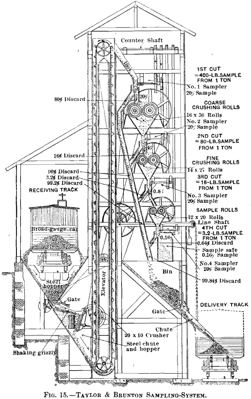
An ideal sampling-mill, where the situation and nature of the service will permit this form of construction, is shown in Fig. 15. This plant is entirely automatic, and when the ore is received in hopper-bottom cars no manual handling is required at any stage, while the sample is automatically delivered into a
locked steel safe. To simplify the drawing, the roll-feeders have been omitted.
Fig. 16 is a vertical longitudinal section of the new Taylor & Brunton mill at Silver City, Utah, completed January, 1909. Like the plant shown in Fig. 15, it is automatic throughout, electric driven, and contains every modern device for facilitating crushing, sampling, and cleaning, the latter operation being performed by compressed air.
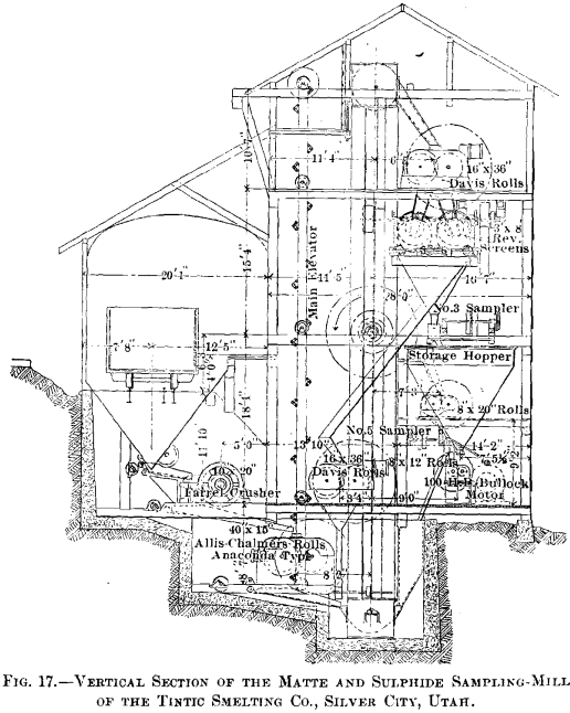
A good example of a modern crushing-, screening-, and sampling-plant is shown in Fig. 17, which is a longitudinal section through the new matte and sulphide mill of the Tintic Smelting Co. at Silver City, Utah.
It is not the purpose of this paper, however, to take up and illustrate details of construction, but rather to show the methods which are being employed to produce the best results in the
valuation of ores; an operation which means everything to the mining and metallurgical industries. One of the first requisites for successful mining is an accurate knowledge of what a property is producing, and this of necessity involves correct sampling, both underground and on the surface. The first essential to success in all metallurgical work is a knowledge of the exact value of the ore going into the works, and of the different products issuing therefrom.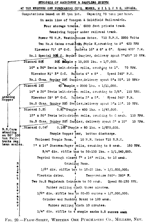
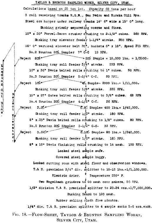
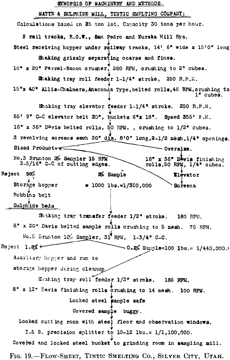
In order to show the methods of operation in vogue in different districts, I present Figs. 18, 19, 20, and 21, which contain the flow-sheets of a number of the newest and largest sam
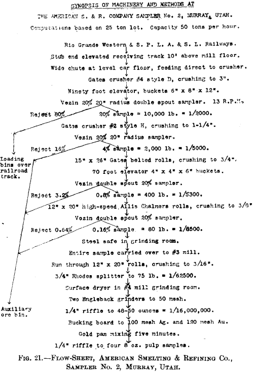
pling-works, clearly showing every detail of the process, and the machinery employed in the alternate operations of crushing and subdivision, as well as the increase of ratio as the final stages are reached. This style of flow-sheet was originally type-written on ordinary 8.5- by 13-in. paper, perforated for a loose-leaf binder. In this way flow-sheets of many classes of operations may be preserved in convenient form.
These flow-sheets show considerable differences at all stages, and a great divergency in the methods of subdividing the final sample. Too many manual operations are in use, and there is no doubt that the complete elimination of the personal equation by using a small Taylor & Brunton splitter with 3/8-in. riffles (shown in Fig. 12) gives by far the most accurate subdivision.
To show how closely results between different mills and repeat-sampling in individual mills may be made to check, the following examples, taken at random, should suffice:
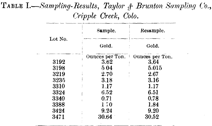
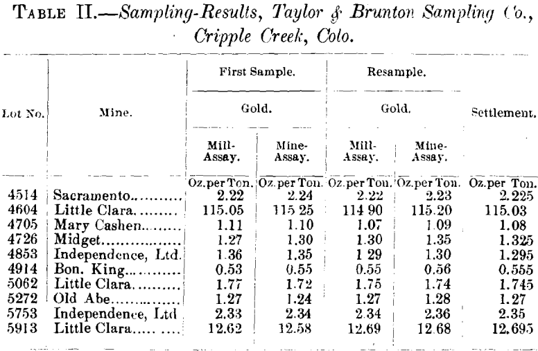
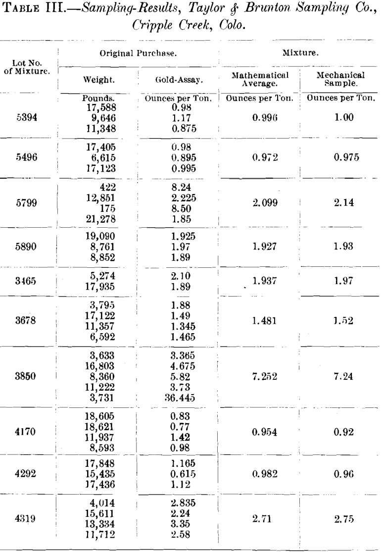
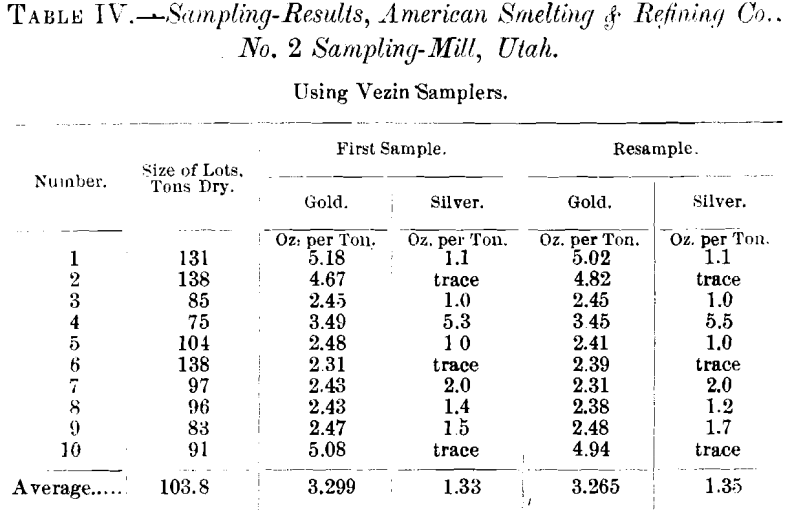
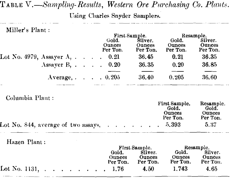
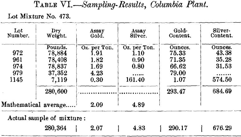
Table VII. gives a comparison on a lot of Bullfrog Pioneer ore sampled at Columbia plant, and afterwards screened through a 3/8-in. screen at Hazen; fines sold to reverberatory and coarse to blast-furnace smelters, actual weights and moistures having been determined both on the fines and the coarse, which makes a showing of a slight loss in weights.
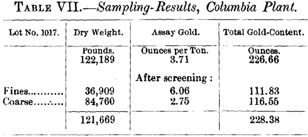
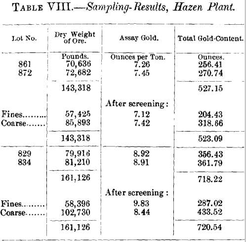
Table VIII. gives a comparison of assays and total ounces of gold contained in four lots of Engineers’ Lease ore from the property of the Florence-Goldfield Mining Co., in Goldfield, Nev., sampled at the Columbia plant and afterwards screened through 3/8-in. punched screen at the Hazen plant, and the coarse and fines sampled separately after screening.
The dry weights show the same in each case, due to the fact that the fines after screening at Hazen were actually weighed and the moisture determined, thus ascertaining the exact dry weight, which was deducted from the total purchased dry weight, making a figured dry weight of the coarse.
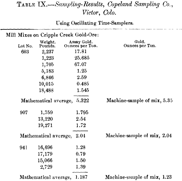
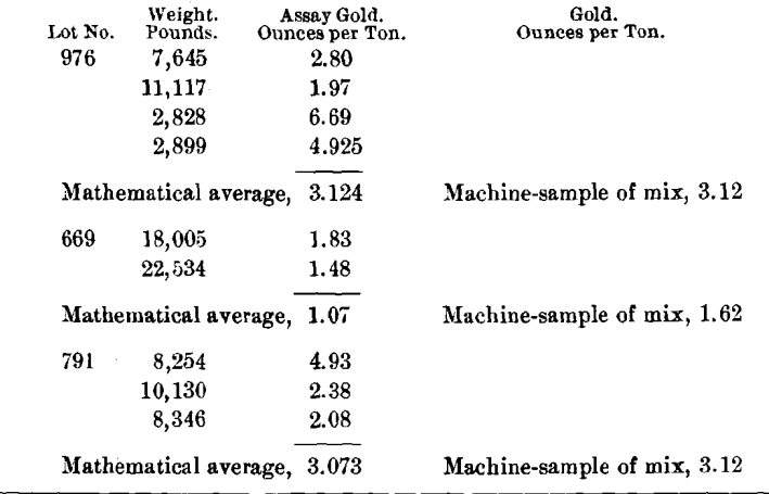
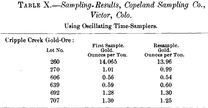
The most convincing tests of correct valuation in ore-sampling are those in which numbers of small lots are bought and paid for individually, and stored for a considerable time, until a sufficient quantity of ore has been collected to form one large lot. When this period arrives the individual lots are not mixed, but run through the mill in succession, and it is usually found that the mechanical sample of the mixture agrees with the calculated average, as determined by the values in the original purchases, as closely as the best control-assays.
The small lots when originally received, sampled, and purchased were coarse and generally wet, but when run through the mill the second time they are both fine and dry, giving thereby the greatest possible dissimilarity in conditions of size of particles and moisture-content. The excellent checks obtained on this class of work show conclusively that with “ time-sampling ” the results obtained are in no way affected by the physical conditions of the ore, and may be implicitly accepted as correct.
The art of sampling has now reached a stage where a standardization of methods is both desirable and possible, and it is to be hoped that the Mining Congress, or the proposed Bureau of Mines, will take the matter under consideration and appoint a thoroughly qualified commission which will give the subject the study and investigation its importance demands. Recommendations by an unbiased, competent board would do much to eliminate faulty methods, and bring about the adoption of standard systems of valuation, which would prove of inestimable benefit to the mining and metallurgical industries from both a business and a scientific stand-point.

