Making a sketch of the pump system, including dimensions, is very helpful in determining the static heads, friction heads, etc. After determining the top size of the solids and solid size distribution by the results of a screen analysis of the material, we can select the materials to be used in the construction of the pump. Having determined the flow rate and the total discharge head, we may now actually size the pump for the given duty.
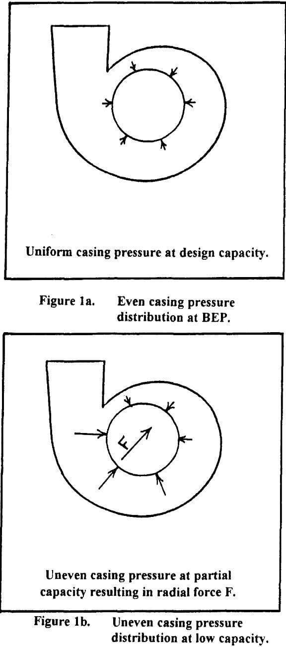
The size selection should be based on the pump operating as near the best efficiency point (BEP) as possible. Operation at or near the BEP will result in an even pressure distribution within the pump volute reducing the radial loading on the bearings giving longer bearing life. (Figure 1a). It will also cause less shaft deflection and increased packing and gland area wear life. Operation off the BEP will result in uneven pressure distribution in the volute causing higher radial loading. (Figure 1b)
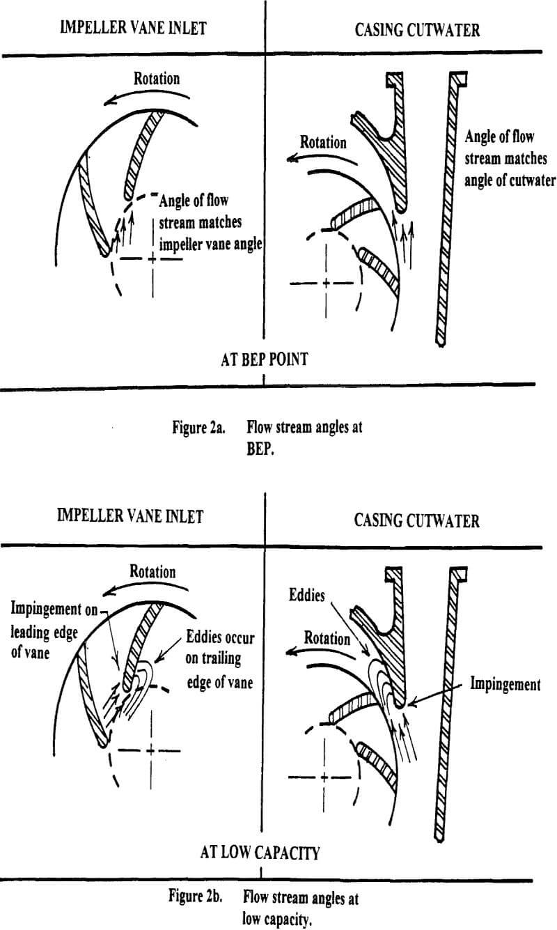
Operation near the BEP will also result in the flow stream passing through the impeller at the same angle as the impeller vanes and the cutwater. (Figure 2a) By matching the flow angle and the vane angles we reduce the impingement of abrasive particles on the wear surfaces of the pump. This greatly increases the wear life of the pump.

Operating at capacities lower than the BEP will result in the slurry impinging on the leading edge of the impeller vanes and creating eddies on the back side of the impeller vanes. The flow exiting from the impeller vanes does not match the cutwater angle resulting in turbulence and wear after the cutwater. (Figure 2b)

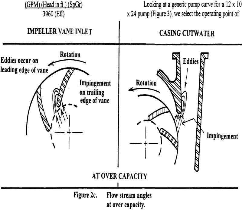
When operating at capacities beyond the BEP again the flow stream does not match the impeller vane angles and the cutwater angle The eddies now appear on the front side of the impeller vanes and on the discharge throat side of the cutwater (Figure 2c)
Operation beyond the BEP can be caused by adding safety factors to head and flow parameters when sizing pumps. This will be discussed in more detail later.
The actual size selection of the pump is such that the required flow is at or slightly to the left of the BEP on the pump curve. The total discharge head must be within the head parameters, as shown on the curve.
The curves for slurry pumps are based on water performance for that pump. The horsepower shown on the curves is clear-water horsepower. In order that the clear-water horsepower be corrected to slurry brake horsepower, we must multiply by the specific gravity of the slurry. This is normally sufficient providing the slurry concentration is not above 5%.


