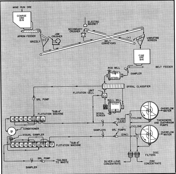
The recovery of silver minerals occurring in a lead- zinc sulfide ore is efficiently accomplished using the above flowsheet. The process consists of selective flotation to produce a mixed silver-lead concentrate for maximum smelter return and a separate zinc concentrate. Over-grinding of silver minerals is detrimental to efficient flotation recovery, so the Unit Cell is used in the grinding circuit to recover a large part of the silver and lead values as soon as liberated.
The flowsheet is for a plant having a capacity in the range of 300 to 500-tons per day.

The Flowsheet
CRUSHING SECTION: The crushing section consists of primary and secondary crushing with intermediate screening. Both crushers are located in the same building and conveniently attended by one operator. A minimum of conveying equipment is required by this arrangement. Dust collecting facilities are, likewise, limited to only one building.
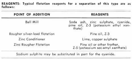
Grinding Circuit: The crushed ore after automatic sampling is subjected to two-stage grinding using a Rod Mill in open circuit and a Ball Mill in closed circuit with a Classifier. The Unit Flotation Cell receives the discharge from the ball mill for recovery of a substantial amount of the granular silver minerals together with galena as soon as freed. Reagents are added to the ball mill. Tramp iron and occasional oversize gangue are removed from the circuit by the Spiral Screen attached to the ball mill and this prevents excessive wear or plugging of the unit cell. The classifier is of the latest design.
The Mineral Jig is not included in the flowsheet, but on many ores of this type it is applicable either alone or with the unit cell. The grade of jig concentrate is usually very high grade and ideal for blending with the flotation concentrate. If native silver or gold values are present, the jig is a very essential addition to the flowsheet and would be used on the rod mill discharge in this case.
Selective Flotation: The classifier overflow is treated in a conventional manner using “Sub-A’’ Flotation Machines of cell-to-cell design which enables double cleaning of the silver-lead and zinc concentrates without the need of pumps. For large tonnage operations the “Sub – A” Free Flow Machine is optional for roughing and scavenging, but the cell to cell type is always used in the cleaner circuits where high selectivity is essential. The two flotation banks are arranged so that the banks face one another and can be conveniently controlled by one operator from a single aisle. Operation of the Conditioner can also be observed from this aisle. A Visual Sampler is used on the zinc tailing to provide an instant means for the operator to evaluate plant results. Some plants find it beneficial to use a visual sampler on the lead tailing ahead of the zinc circuit. The Visual

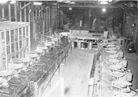
General view of the flotation section at a modern silver-lead-zinc mill. The lead circuit is on the left and the zinc circuit is on the right.
Sampler is also useful for evaluating the lead or zinc concentrate.
Thickening and Filtering: The silver-lead concentrate (including the unit cell concentrate) and the zinc concentrate are separately treated through wet cyclones to remove the coarse sulfides as thick underflow products suitable for direct filtration. The cyclone overflow products are ideally suited for thickening and subsequent filtration with their respective cyclone underflows. This procedure avoids any overload of heavy sulfides in the thickeners and, therefore, simplifies the operation of the thickeners. SRL Pumps are engineered for use with wet cyclones and give trouble-free service.
Sampling: In addition to the feed sample, which is cut by means of a Type “C” Automatic Sampler, the final silver-lead and zinc flotation concentrates are sampled using Type “B” cutters. The final plant tailing is also sampled in the same manner.

Summary: This flowsheet incorporates all features of a modern day mill for optimum efficiency and general simplicity for ease of operations. Instrumentation devices can be included to facilitate automatic control of the plant circuits if desired.
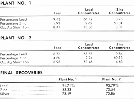
Typical Metallurgical Results
Many factors affect the metallurgical results of every plant. However, in a study of this type it is interesting to note the recoveries and grades that are actually being made at successful mills. The figures of these two plants are included for their value in making economic studies of new deposits.

SHIFT SCHEDULING SOLVES PROBLEMS IN CONTINUOUS OPERATION
A new mill commencing continuous operations or an existing plant that has not been working on a continuous basis is often confronted with planning a work schedule for employees when converting to a three-shift, seven-day per week operation.
This problem can be approached in a number of ways, but the schedule below is particularly convenient for all employees. Four crews are required to continually fulfill the three-shift requirements. In the table the crews are designated as “A”, “B”, “C”, and “D” and a four-week schedule starting with Monday is shown.
During this four-week period it will be noted that each crew will have four consecutive days off and these will be on Monday, Tuesday. Wednesday, and Thursday. The schedule can be shifted forward or backward if a different group of days should be more desirable. The general pattern of the schedule is: 7 day shifts — 4 off; 7 graveyard shifts—2 off; and 7 swing shifts— 1 off during each four-week period. The schedule repeats itself every four weeks.
The shaded portion indicates a typical schedule for shift “B”.

