Table of Contents
Construction of a 250-p.s.i.g. helium-recycle system to operate with gas temperatures as high as 2,500° F. appears feasible. More development work is required, however, on heat exchangers and compressors.
Many problems inherent in large nuclear systems are not present in the pilot-scale ISR system. Although the cooler in the ISR loop operated satisfactorily, thermal expansion and leakage likely will be problems in larger heat exchangers. “Canning” can be used to prevent helium leaks from small compressors but gastight shaft seals will be required on larger units. Also, in a large system, compressors with gas-lubricated bearings might be used advantageously to avoid contaminating the helium with lubricants.
The deterioration of alumina-silica refractories in the ISR indicates that they are not suitable for use in high-temperature helium. Porous carbon performed satisfactorily, and contamination of the recycled helium by gases occluded in the structural materials was greatly reduced.
Leakage of helium in the loop probably can be limited to less than 1 std. c.f.h. At the octagonal ring joints, sealed with annealed-copper rings, no leakage of helium at 1,000° F. and 250 p.s.i.g could be detected. Although the bellows-seal valves performed satisfactorily during the 1,000-hour run, other tests have shown that this type of valve is not reliable for continuous service. When such valves are operated frequently, failures sometimes occur in the metal bellows. Further testing will be required to demonstrate the reliability of valves for continuous use in 1,000° F. helium.
As part of a joint program of the U.S. Atomic Energy Commission and the Federal Bureau of Mines for using nuclear energy to supply process heat, the Bureau designed and constructed a pilot-scale simulated nuclear reactor system. Although workable components were developed, the simulated nuclear reactor could not be operated continuously at its design conditions of 2,500° F. and 250 p.s.i.g. because the refractory materials used for insulation deteriorated. Replacement of these materials with porous carbon permitted sustained operation at design conditions, and a 1,000-hour demonstration run was completed successfully.
No serious operating difficulties developed during the test. Leakage of helium after 1,000 hours was only 3 to 4 std. c.f.h. Inspection after the run revealed no damage to any of the components.
Including earlier runs during previous research the system has been operated about 4,000 hours, of which 1,120 hours have been at 2,500° F. or higher. The helium-recycle compressor performed satisfactorily with no maintenance whatever for 2,445 hours, with about 2,000 hours at 900° to 1,000° F.
As part of a continuing program to reduce the cost of producing synthetic liquid and gaseous fuels from coal, the Federal Bureau of Mines, in cooperation with the U.S. Atomic Energy Commission (AEC), has begun research on the use of high-temperature nuclear heat for the gasification of coal with steam and for other chemical processes. The indirect cycle, in which heat from a gas-cooled nuclear reactor is transferred to process streams in an external heat exchanger, was chosen for the initial development. The Bureau already has demonstrated the feasibility of gasifying low-rank coals in externally heated alloy-steel tubes.
The Bureau designed and constructed a high-temperature, simulated nuclear helium-recycle loop to operate at 2,500° F. and 250 p.s.i.g. to develop and test components and demonstrate the feasibility of a high-temperature gas-recycle system. Heat for the system is provided by electric induction because it most nearly simulates the type of heating furnished by nuclear fuel. Heat, generated within a bed of graphite spheres that simulate nuclear fuel elements, is transferred to a pressurized stream of recycled helium that can heat chemical process streams to 1,800° F. in an external heat exchanger.
Because the energy required to circulate hot helium through the system decreases rapidly with increase in helium pressure, the proposed nuclear system is particularly well adapted to pressure-gasification processes. Most gas-synthesis processes require gas at pressures of 20 atmospheres or more. When these gases are generated at the required pressure, considerable savings are made in compression costs. Also, stresses of the metal tubes in the gasifier (heat exchanger) are reduced to a minimum by balancing the pressure of the unreactive helium on one side of the tubes with the pressure of the reducing gases and steam on the other side.
Objectives of the development of the prototype system are twofold:
- To reveal and solve the engineering problems connected with the design, construction, and operation of the system and its components, particularly those relating to heat transfer and fluid mechanics of high-temperature helium, so as to advance nuclear process-heat technology.
- To obtain information for the design, construction, and operation of a coal gasifier (heat exchanger) that can transfer nuclear heat to a steam-coal mixture with virtually no radioactivity imparted to the product gas.
Description of the Loop
A simplified flowsheet (fig. 1) shows the induction-heated, simulated nuclear reactor (ISR) system. Figure 2 shows the pilot-scale installation.
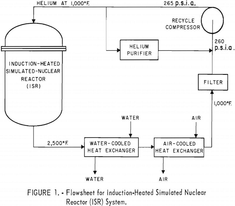
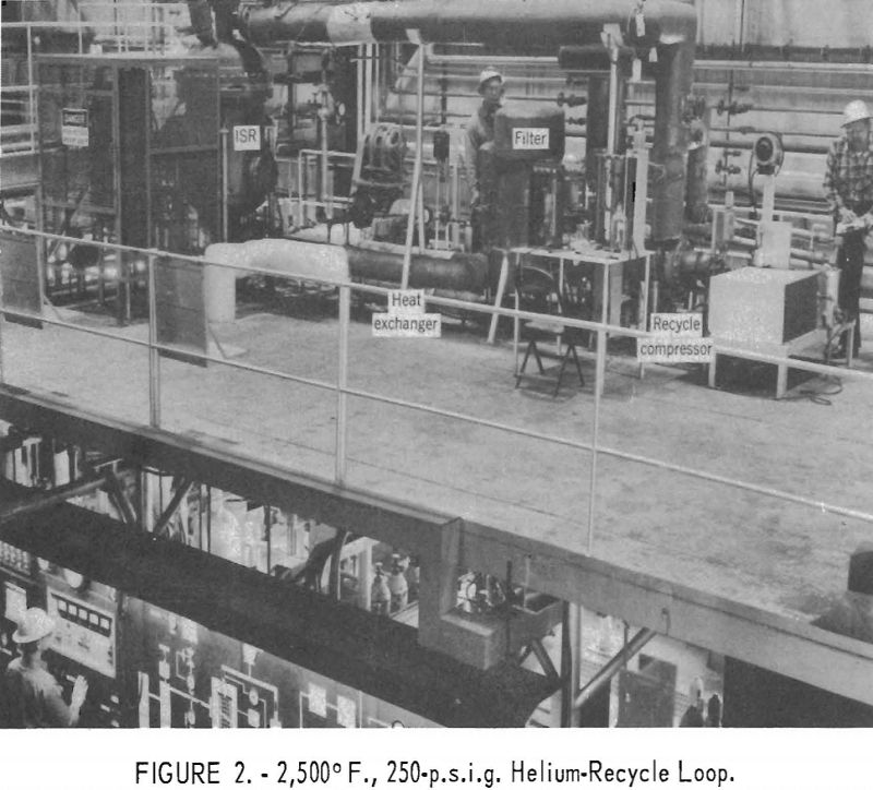
A recycle compressor circulates helium through a gastight reactor vessel containing a bed of graphite spheres heated by an electric induction coil. The helium, which can be heated to 2,500° F. , is cooled to 1,000° F. or lower in a concentric-pipe heat exchanger, filtered, and recirculated to the reactor.
All the system components were described in a previous report. Subsequent modifications and the operating performance of the equipment are discussed in this report.
Induction-Heated Simulated Nuclear Reactor (ISR)
For the runs that preceded the 1,000-hour test, the ISR was constructed as shown in figure 3. The shell is a type-304 stainless steel pressure vessel designed for 300 p.s.i.g. and operated at 250 p.s.i.g. Helium enters the top of the vessel at 1,000° F. and flows downward over a 6-inch-diameter, 24-inch-high bed of graphite spheres heated by an electric induction coil. The helium leaves the reactor at 2,500° F. through a refractory-lined nozzle and is piped to the heat exchanger.
In the original design (fig. 3) the spheres were contained by a silicon carbide tube that was inside a zirconia or alumina insulating tube. Granular alumina between the tubes helped to reduce heat loss. The helium outlet consisted of silicon carbide tubes insulated by K-28 brick (45 percent Al2O3, 52 percent SiO2). Fiberfrax, a fibrous alumina-silica insulating material, insulated the sphere-containing assembly from the shell.
During operation, deterioration of these materials became a serious problem. The K-28 insulating brick was replaced with porous-carbon blocks. A KT-type silicon carbide tube was used to replace the containment tube of normal silicon carbide, and the zirconia insulating tube was replaced with a tube of silicon carbide foam.
Normal silicon carbide is a ceramic-bonded silicon carbide (89 percent SiC), whereas KT silicon carbide is a dense, self-bonded silicon carbide (96.5 percent SiC). Silicon carbide foam is a lightweight, open cellular form of self-bonded silicon carbide. Figure 4 shows these materials.
Figure 5 is a view looking down into the bottom of the partly assembled ISR. In the center is a slotted disk of silicon carbide that rests on a tube of porous carbon. Around the disk is a 7-inch-deep section of porous-carbon fragments and bricks. Fiberfrax, the white ring between the bricks and the vessel wall, provides additional thermal insulation. The two tubes seen at the left are leads for the induction-heating coil. Porous-carbon bricks and fragments were used instead of larger units to increase the interfaces within the carbon, thereby increasing the electrical resistance and minimizing heating from the induction field.
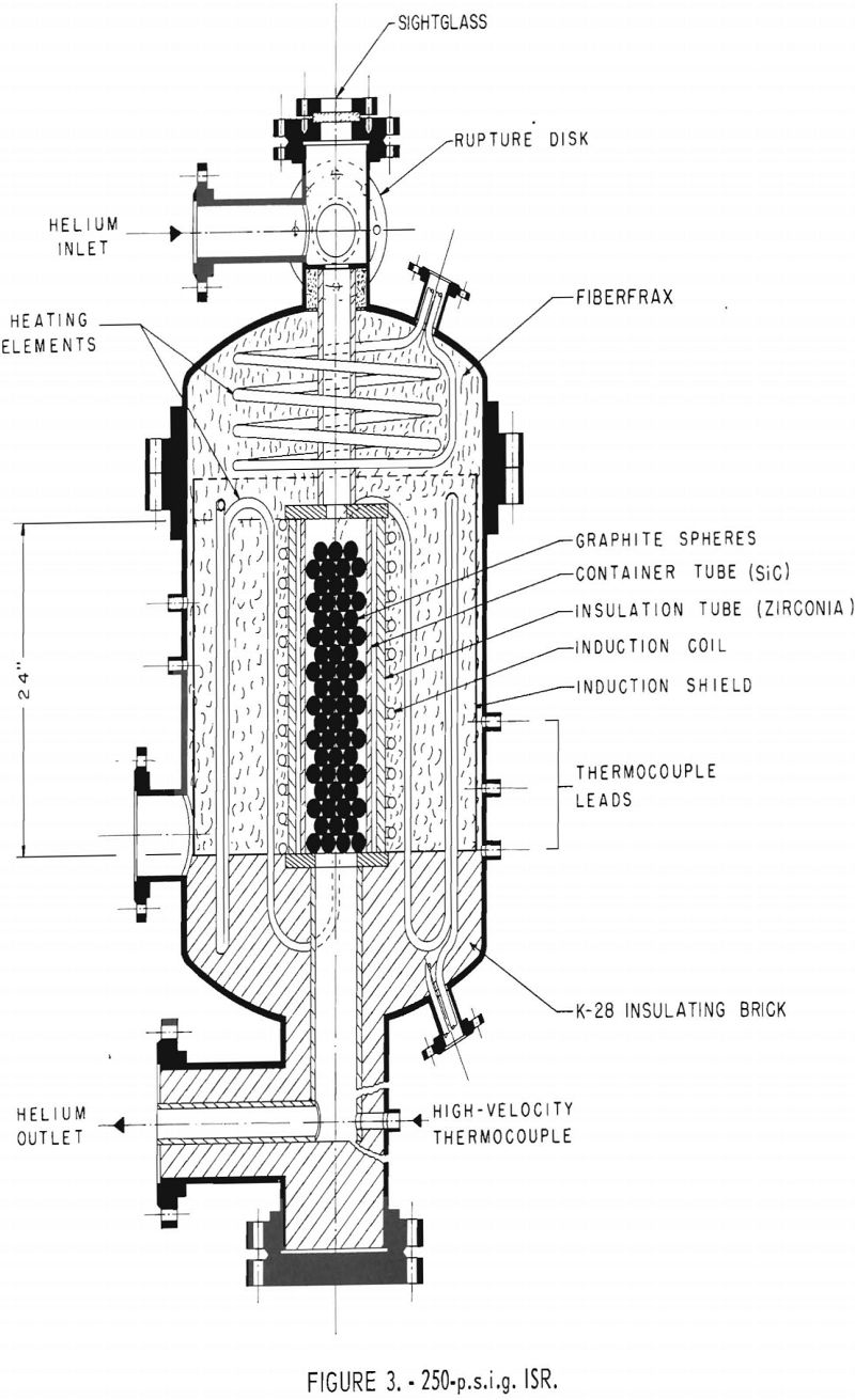
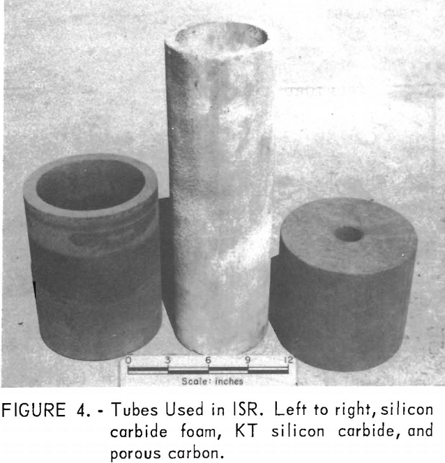
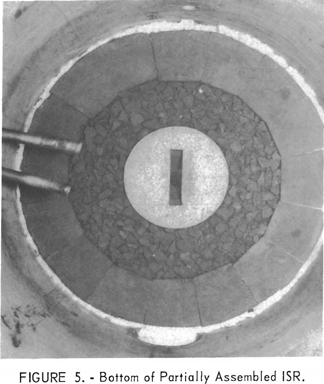
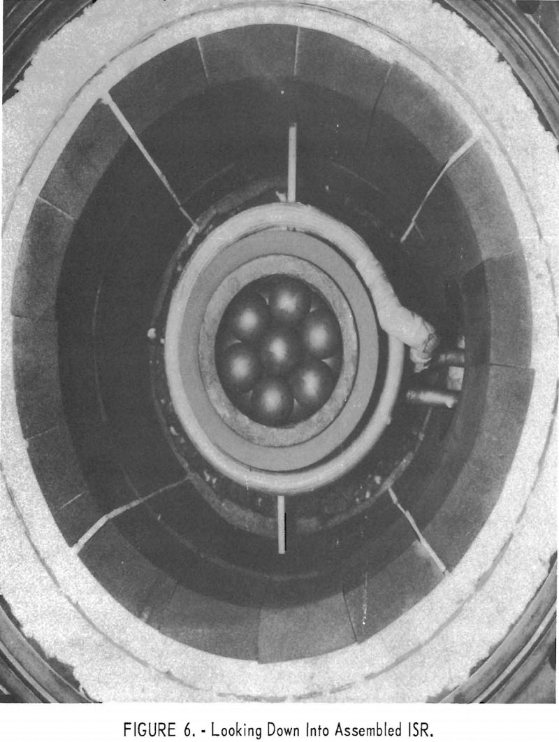
Figure 6 shows the assembled ISR. The 2-inch graphite spheres are inside the KT silicon carbide tube that rests inside the silicon carbide foam insulating tube. The water-cooled induction coil that provides the field for heating is outside the insulating tube. The porous-carbon bricks are backed up by two layers of Fiberfrax separated by a copper sheet that shields the vessel wall from the induction field. Thin refractory inserts at four places in the carbon-block assembly increase the electrical resistance of the assembly and thereby reduce inductive heating.
During electrical load-matching tests with the new materials, the KT silicon car-bide containment tube heated inductively because of its high electrical conductivity at elevated temperatures. In addition, the KT silicon carbide tube cracked and a siliceous substance from it or from both it and the silicon carbide foam insulating tube cemented them together. Therefore, the KT and foam tubes were replaced with tubes of normal silicon carbide and zirconia, as in the original installation (fig. 3). After 50 hours of operation at the design conditions of 2,500° F. and 250 p.s.i.g., excessive pressure drops in the loop caused termination of the test. Inspection revealed that siliceous deposits, probably originating from the silicon carbide, had caused the high pressure drops. Figure 7 shows some of these deposits on the outer surface of the silicon
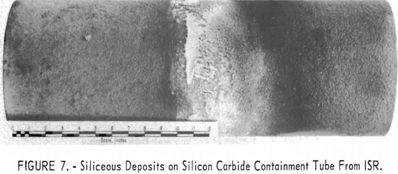
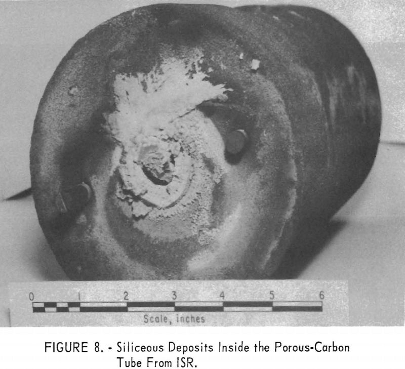
carbide containment tube. The 1%-inch-inside-diameter porous-carbon tube from the outlet nozzle of the ISR was almost completely plugged with this material (fig. 8).
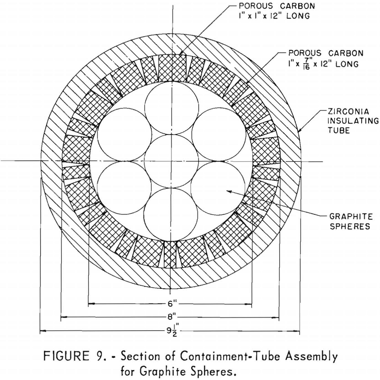
The porous carbon, however, was in good condition. Because all evidence pointed to the silicon carbide as the source of the deposits, the silicon carbide containment tube was replaced with a tube of porous carbon, but inductive heating of the porous carbon was excessive during subsequent tests. Therefore, the porous-carbon tube was replaced by strips of porous carbon fitted longitudinally against the inner surface of the zirconia tube as shown in figures 9 and 10. This arrangement provided many high-resistance joints that reduced inductive heating of the porous-carbon liner. Figure 10 shows the final interior ISR assemblage, and figure 11 shows a cross-section of the final ISR assemblage.
Deterioration of insulation was eliminated, and a sustained run of 1,000 hours at the design conditions of 2,500° F. and 250 p.s.i.g. was satisfactorily completed.
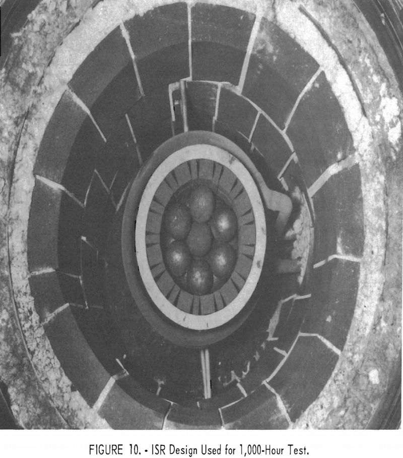
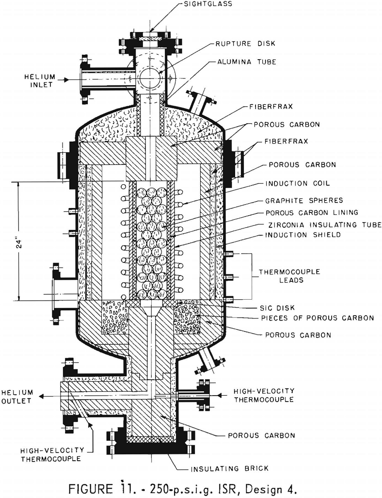
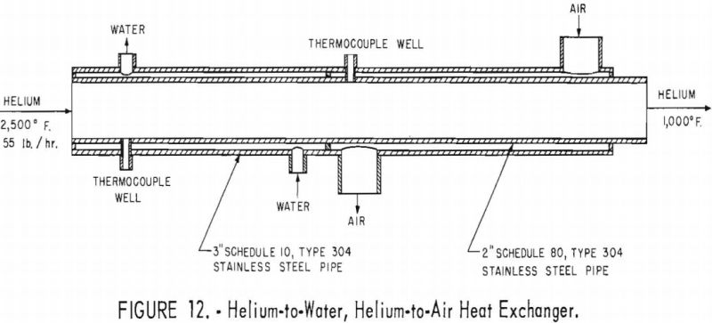
Figure 12 shows the 7½-foot-long concentric-pipe heat exchanger used in the 1,000-hour test. The annulus between the pipes is partitioned into two sections. Water flowing countercurrently is the coolant in the hotter section, and air flowing countercurrently cools the helium in the downstream section.
Helium-Recycle Compressor
The helium-recycle compressor (figs. 13 and 14) is a single-stage centrifugal type with overhung impeller, diffuser, and drive motor. The motor-compressor assembly is “canned,” but is flanged for easy disassembly. The compressor increases the pressure of 1,000° F. helium from 260 to 265 p.s.i.a.
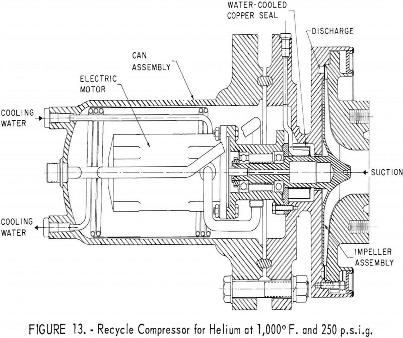
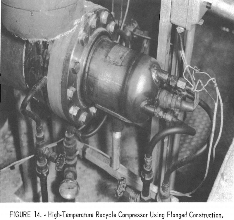
The rotor is made of W-545 alloy (13 percent chromium, 25 percent nickel, 3 percent molybdenum, and 1 percent boron). Bearings are of the Barden-sealed type, and the grease is Military Specification L-7711, Barden Specification G-19. The motor and compressor bearings are water cooled. Temperature of the bearing nearest the impeller does not exceed 140° F.
Dust Filter
The dust filter is designed to protect the recycle compressor from particles entrained in the helium. The filter vessel is type 304 stainless steel and is flanged at the top and bottom. A rectangular filter element made of Fiberfrax packed between parallel screens, placed longitudinally across the centerline of the vessel, gives a 1- by 3-foot filter surface.
Helium-Purification System
Because gaseous impurities, mostly oxygen and water vapor, are occluded in the materials of construction in the ISR, a 1 to 2 percent side stream of the helium must be continuously purified. As originally installed, the purification system comprised a vessel with hot copper turnings, freon-cooled condensers, and a phosphorous pentoxide drying unit. In this system, oxygen combined with the copper, and hydrogen a product of the steam-carbon reaction-reacted with oxygen to form water that was removed by the condensers and phosphorous pentoxide drying unit.
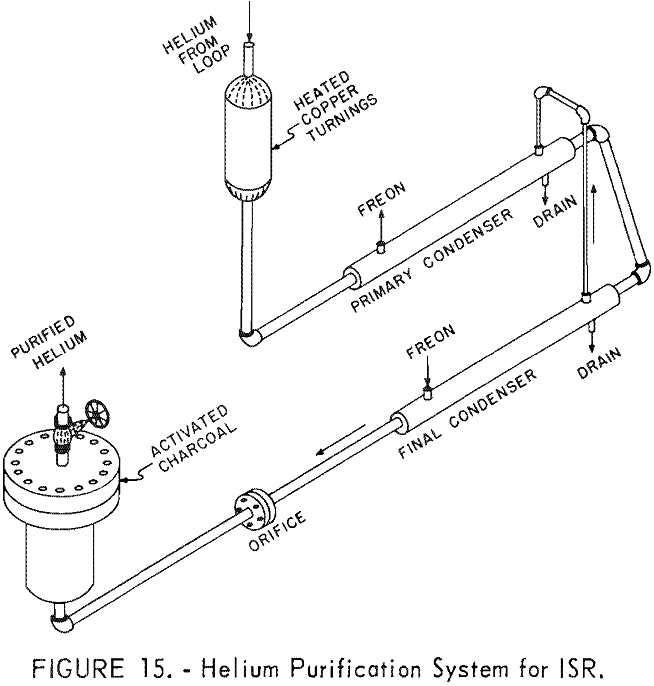
Because laboratory tests showed that sulfur-bearing gases evolve from porous carbon at temperatures above 2,100° F., the helium-purification system was modified before the 1,000-hour run to provide for sulfur removal (fig. 15). Normally, negligible quantities of sulfur-bearing gases evolve from the porous carbon below 2,100° F., so contamination of the helium was not expected to be a serious problem, but, as a precaution, the phosphorous pentoxide in the purification system was replaced with activated charcoal to adsorb any sulfur-bearing gases.
Performance of ISR System During 1,000-Hour Test
The ISR operated continuously for 1,000 hours with helium flowing at 5,000 std. c.f.h. and 250 p.s.i.g. Helium entered the reactor at 1,000° F. and was heated to 2,500° F.
At the end of the 1,000-hour test, helium leakage was only 3 to 4 std. c.f.h., or about 2 to 3 percent of the system capacity. Most of the leaks were concentrated where the induction coil enters the ISR and through the diaphragm of inch-diaphragm valve in a gas-sample line. No leaks were detected at the octagonal ring-joint flanges sealed with annealed-copper rings. A Veeco Mass Spectrometer Leak Tester, Model MS-9A, was used to check for leaks.
All units operated satisfactorily. Additional details about the main components are given below.
Induction-Heated Simulated Nuclear Reactor
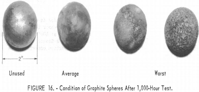
Throughout the test there was no evidence of refractory deterioration and no major difficulties with the ISR. Internal inspection revealed no damage to the porous carbon, not even to the lining for the graphite spheres. The zirconia insulating tube was cracked, probably by thermal shock, but showed no signs of deterioration. All graphite spheres were in good condition, except those in the hottest part of the bed, about 18 to 20 inches from the top. A few of these spheres had undergone chemical attack, probably by reaction of the graphite spheres with small amounts of water occluded in the materials of construction (fig. 16).
Of the average 85 kw. (290,000 B.t.u./hr.) input to the induction coil, about 29 kw. (99,000 B.t.u./hr.) were transferred from the sphere bed to the recycled helium.
Helium-Recycle Compressor
This unit performed satisfactorily with helium at 950° to 1,000° F. It has now operated without maintenance for 2,445 hours, with about 2,000 hours at 900° to 1,000° F. During the 1,000-hour test the bearings were checked daily by measuring the vibration of the machine. Vibrometer readings of 0.001 inch did not increase throughout the test. Temperature of the bearing nearest the impeller never exceeded 140° F.
Heat Exchanger
The concentric-pipe heat exchanger operated satisfactorily throughout the test, cooling the helium from 2,500° F. to approximately 1,150° F, a heat duty of about 89,250 B.t,u./hr. (As a result of heat losses from the system the temperature of the helium entering the compressor was about 950° to 1,000° F.) About 70 percent of the cooling, or 62,800 B.t.u./hr was done by the 200 g.p.h, of water in the water-cooled section. Temperature of the helium leaving the water-cooled section was about 1,550° F. Temperature of the water at the inlet to the cooler ranged between 65° and 80° F.; temperature rise of the cooling water was about 38° F. The overall coefficient of heat transfer in the water-cooled section was approximately 18.5 B.t.u./ (hr.)(sq.ft.)(° F.), In the air-cooled section of the exchanger, about 6,000 std. c.f.h. of air further cooled the helium to a temperature of 1,150° F. Air entered the cooler at 100° F. and left at about 330° F. The overall coefficient of heat transfer in the air-cooled section was about 10.5 B.t.u./(hr.) (sq.ft.) (° F.).
Dust Filter
Inspection revealed only small amounts of dust on the filter element. This dust probably accumulated during earlier tests when silicon carbide tubes were still being used. The relatively clean filter illustrates that refractory deterioration in the ISR was negligible.
Helium-Purification System
Contamination of the recycled helium by gases occluded in materials of construction has been greatly reduced. Before the 1,000-hour test, the ISR system was precleaned three times by circulating helium at 800° F. for 3 hours, bleeding to atmospheric pressure, then evacuating with a Stokes vacuum pump. Evacuating the helium at 800° F. prevented the construction materials from readsorbing the contaminants.
Probably a more important factor in reducing troubles caused by contaminants was the replacement of the alumina-silica bricks with porous carbon. In earlier runs, water of crystallization from the deteriorated insulating bricks reacted with the graphite spheres. This did not occur with the porous carbon, as shown by the good condition of the graphite spheres after the 1,000-hour test (fig. 16).
