Table of Contents
In order to simulate a grinding circuit, it is necessary to obtain valid mathematical models of the grinding mills and classifiers in the circuit. Several models of grinding mills have been proposed and models of cyclone classifiers are available.
Description of a Circuit
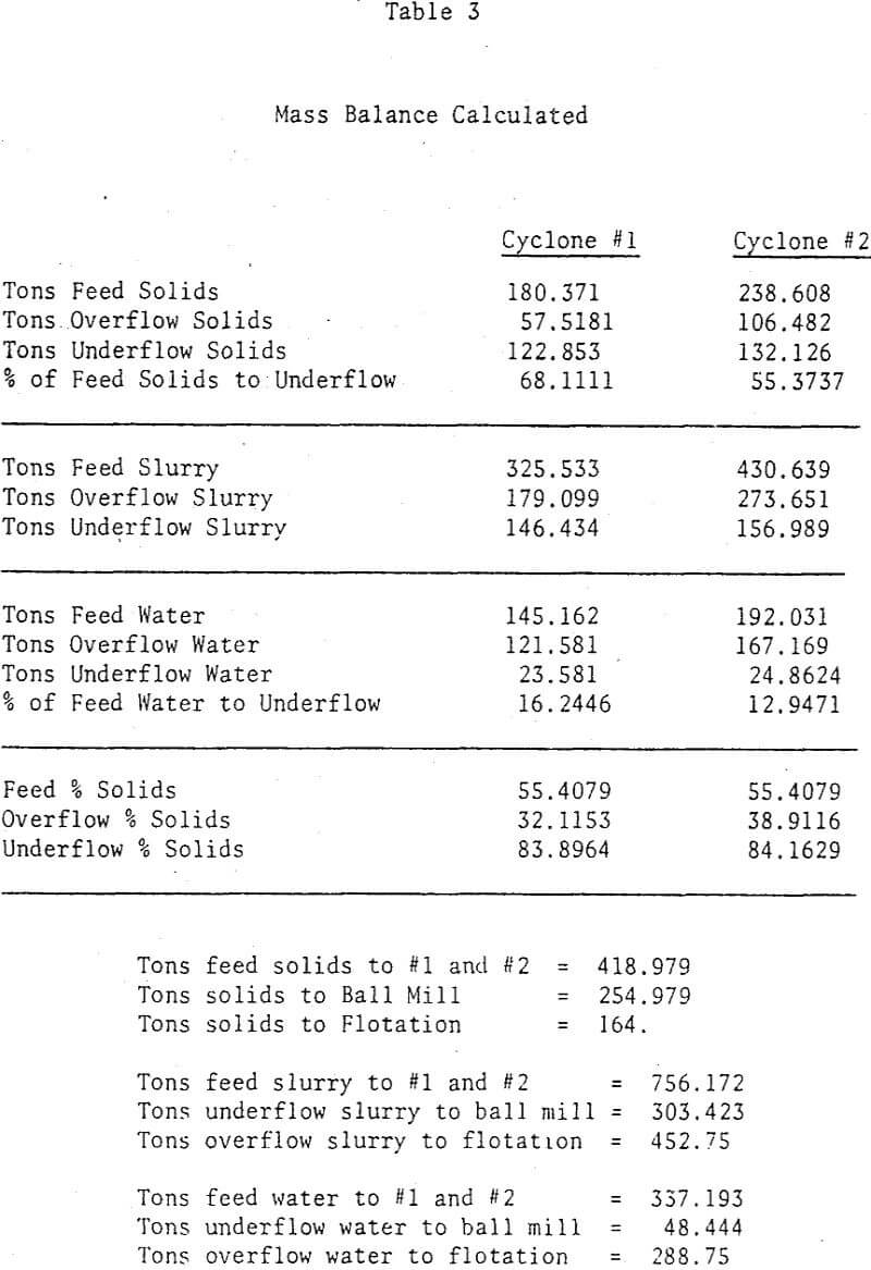
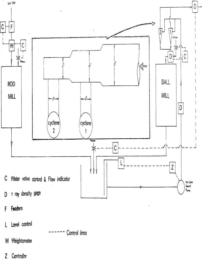
New feed enters an open circuit rod mill at a rate of 164 TPH (dry). The rod mill discharges to a sump, where the slurry joins with slurry that discharges from a ball mill in closed circuit with two Krebs 20″ cyclones in parallel. The contents of the sump are pumped to the cyclones. Cyclone underflow slurries are recycled to the ball mill, while overflow slurries are sent to flotation.
After careful reflection, it is apparent that with this feeding arrangement, feed solids will not split equally between the two cyclones. Cyclone 2 is treating a higher tonnage. Moreover, the characteristics of slurry flow lines within this feeding system are such that coarse solids probably tend to by-pass cyclone 1. Likely, cyclone 2 is treating more of the coarser feed solids. These preliminary considerations have important implications as we shall see.
Lynch Model of a Cyclone
The cyclone model developed by Lynch et. al. consists of a set of four equations each of which contains a parameter which is a constant for any given ore and cyclone combination. These equations are:
The Reduced Performance Curve

where
Y(corr) is the weight fraction of feed of size d undergoing classification which appears in the cyclone underflow, corrected for short circuiting.
a is a constant
X is the ratio of d/d50 (corr)
d50(corr), is the size of classified feed solids, half of which goes to underflow and the other half to overflow.
The Capacity Equation
![]()
where
Q is the cyclone capacity, mass or volume of slurry/time
K1 is a constant
VF is diameter of vortex finder, inches
P is pressure at feed inlet, PSI
FPWAT is percent of water in feed, by weight
The d50(corr), Equation
![]()
where
K2 is a constant
A1 is a constant equal to 1/2.6 for Lynch’s work
A2 is a constant equal to -1/3.5 for Lynch’s work
A3 is a constant equal to 1/10.7 for Lynch’s work
A4 is a constant equal to -1/52 for Lynch’s work
(SPIG) is the spigot diameter, inches
(WOF) is the mass of water in the overflow, tons/time
The Overflow Water Equation
![]()
where
K3 is a constant
B1 is a constant equal to 1.1 for Lynch’s-work
B2 is a constant equal to -10 for Lynch’s work
(WF) is the mass of water in the feed slurry, tons/time
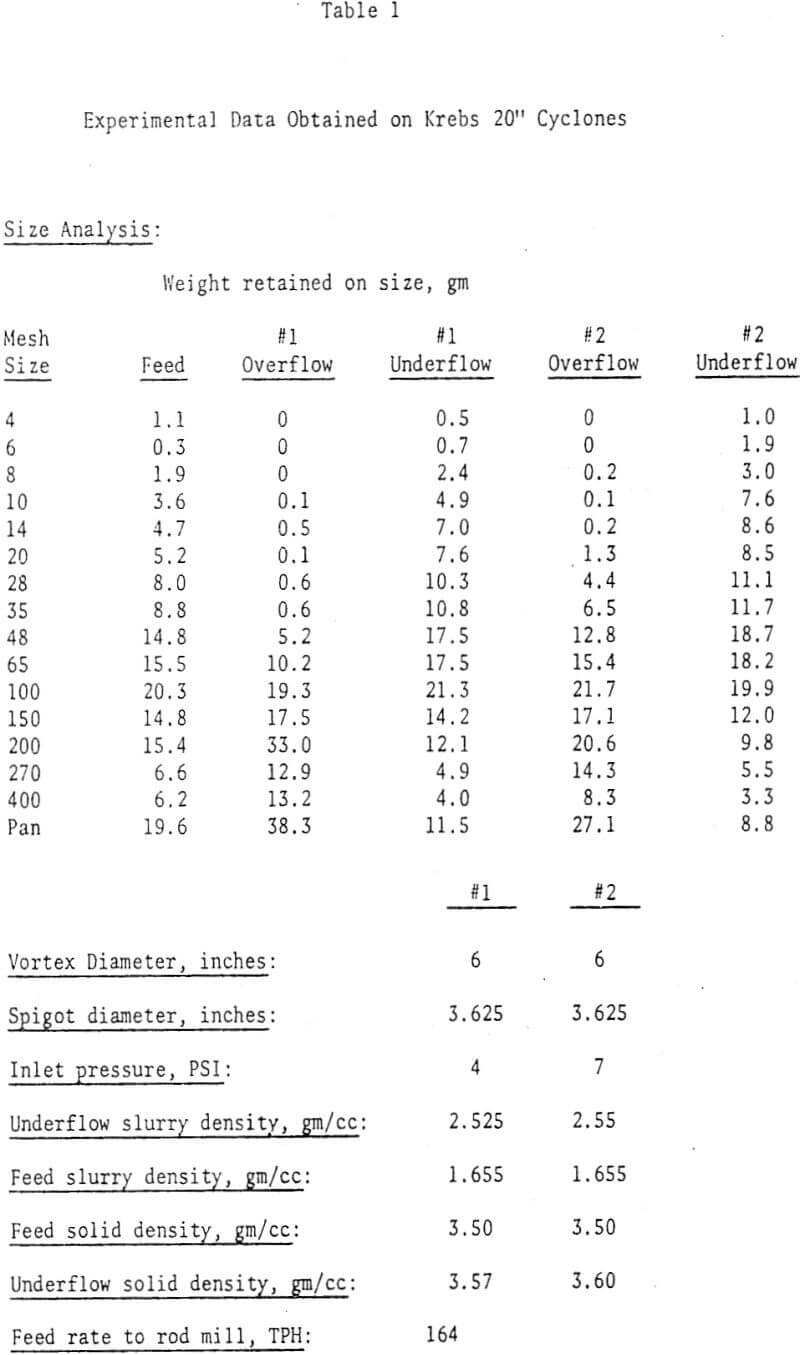
Computational Procedure to Obtain Constants for Cyclone Model
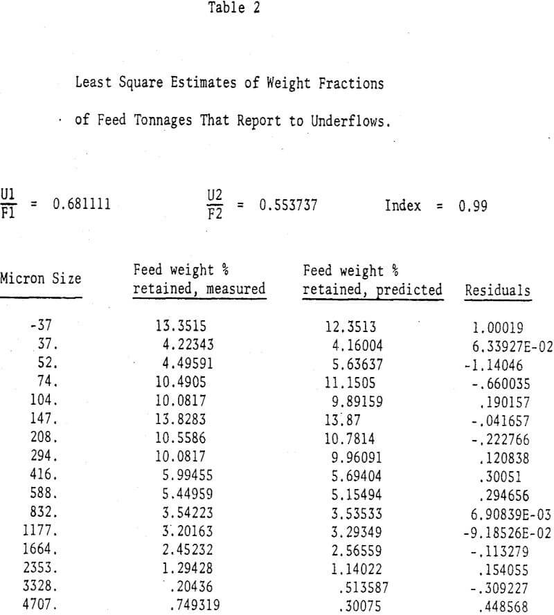
A useful initial step for subsequent calculations is to make a solids and water balance around each cyclone. From a mass balance around a given cyclone for each size fraction, it may be shown that

where
f1 and f2 are weight percents retained on size in feed to 1 and 2 respectively.
u1 and u2 are weight percents retained on size in underflows from 1 and 2 respectively.
o1 and o2 are weight percents retained on size in overflows from 1 and 2 respectively.
U1 and U2 are tons of underflow solids leaving 1 and 2 respectively.
F1 and F2 are tons of feed solids entering it 1 and 2 respectively.
From steady state considerations it may be shown that

where W is the tons of solids being fed to both cyclones. Both cyclones are identical in dimensions, so both should have similar capacity equations (the constant K1 should be the same for both).
