Table of Contents
- Mixer Settler
- Mixer Box
- Introductory Slot and Picket Fences
- Weirs
- Surge Tanks
- Process Sump
- Flotation Cells
- Pumps
- Crud Removal
- Plant Control
- General
- Flowsheet Selection
- Rapid Mathematical Method for the Prediction of Raffinate Copper Concentration
- Description of Process Design Procedure
- Mass Balance Process Flowsheet, and Equipment Design
- Process Flowsheets
- Equipment Design
- Impeller and Draught Tube
- Draught Tube
- Mixer Impeller Drive Units
- Notes
- Design of Top Baffle
- Design Critera
- Settler Design
- Introductory Slot and Entry to Settler
- Slot Area and Number Off
- Positioning of Introductory Slots



 Mixer Settler
The Mixer-Settlers are of the pump-mixer type in which the Mixer Impellers, in addition to mixing the process liquors, also provide the pumping head necessary to transfer them between stages. The variable speed Impellers can be used either with, or without, spoiler blades, the design of which is such that when fitted the increased power is almost wholly available for mixing.
Mixer Box
The Mixer Box is equipped with concentric Draught Tubes having anti-swirl Vanes. The Organic solution is introduced directly into the eye of the Impeller via the central tube, and the Aqueous by the outer one. This technique reduces the differential head required to be produced by the Impeller and, consequently, the power requirements. The Top Baffle or Vortex Breaker of the Mixer Box is specially designed to facilitate installation and removal. The top plate is free of large surface projections which would interrupt solution flow, and is also removable for cleaning purposes should there be any build up of deposits. A soft seal is incorporated between the Baffle and Mixer Box lining to prevent fretting and by-passing of solution.
Introductory Slot and Picket Fences
The fluid dispersion is introduced to the Settler Introductory Slot over a greater width than appeared in earlier designs for the purpose of reducing dead areas to a minimum. Two types of Picket Fences are used on the Settler, being positioned to maximise Settler efficiency. The front Picket Fence is adjustable laterally whilst the other can be lifted clear of the liquors.
Weirs
The separated Organic solution is removed from the Settler Tank via the fixed Organic Weir. The Aqueous solution underflows this Weir and overflows into the Aqueous Weir. This Weir is adjustable vertically and two outlets are used, one serving the Recycle line and the other Interstage solutions. Previous experience has led to this modification for the purpose of improving Plant operation by steadier and constant Flow Conditions.
Surge Tanks
The Loaded Organic Tank is sized to accommodate normal operational requirements plus the contents of a Mixer-Settler. Facilities are provided for removing entrained Aqueous solution and for returning this to the Extraction Section. Two Storage Tanks are provided for Advance Electrolyte solution (2 hour capacity at design flow.) To facilitate construction the dimensions of the Loaded Organic and Advance Electrolyte Tanks are the same.
Process Sump
The Process Sump is divided into two compartments to enable separation of the chloride and chloride containing solutions to be accomplished. Each compartment will hold approximately the contents of one Mixer-Settler.
Flotation Cells
The Raffinate and Advance Electrolyte lines convey solutions leaving the Mixer-Settlers through Flotation Units where recovery of the Organic Reagent takes place. The froth is collected in an overflow Tank and returned into the S-X circuit.
Pumps
Since many of the discharge heads required are very similar, Pumps have been selected with a view to standardisation on driving motors and spare parts, (e.g. Flotation Pumps) and the seals specified will not allow more than a minimal amount of water into the process liquors. The Organic Make-up Pump is capable of supplying the LIX 64N and Tridecano accurately (with 0.5% at full capacity) at the design 40 : 60 ratio, and is sized to serve present and future streams on a batch basis.
Crud Removal
Facility is provided to enable Crud to be removed from the Settlers and to be pumped to two storage vessels which are sized to accommodate about 1 months accumulation.
The Crud is treated in two Centrifuges arranged in series, the Organic being recovered from the first Unit and the Aqueous from the second Unit. Solutions thus recovered are returned to the Sump.
Plant Control
The plant is provided with sufficient surge capacity and Instrumentation to ensure continuing and smooth operation with the minimum of operator involvement. Major process variables may be monitored in the central control room, whilst Emergency Alarms and trips are also provided.
General
Materials of construction have been selected to provide an acceptable balance between durability and initial cost.
The Process Plant is located in the open, but the Mixer Settlers, Tanks and Sump are provided with roofs to prevent ingress of dust and sand and to, reduce loss of the organic phase by evaporation.
Flowsheet Selection
Countercurrent System
A Conventional countercurrent flowsheet (Fig. 3.2.1) will normally be selected for pregnant liquors having compositions from 1 to 10 gpl Cu 2+, as countercurrent operations are the most efficient inasmuch as stripped organic is contacting the weakest aqueous solution. Alternative flowsheets may be considered for pregnant liquor compositions outside this range.

Crossflow System (See Fig 3.2.2)
In general this flowsheet may be useful for pregnant liquor feeds with more than 15 gpl Cu 2+. The maximum working solubility of LIX in kerosene is 40 Vol % which can give a maximum loaded organic concentration of 10 gpl Cu 2+ (maximum LIX loading 0.25 gpl Cu/% LIX, although normally choose to work at about 70% of this).
A conventional countercurrent flowsheet used with high strength pregnant liquor feeds would require using a large overall organic to aqueous ratio, and with DPG mixers it would be necessary to recycle large amounts of aqueous to maintain the operating O/A ratio in the vicinity of the optimum of 1:1 for copper systems.
The crossflow system has the advantage that all extraction stages work at 1:1 without the need for recycle. In each stage the organic is loaded to its working level, and the concentration of the aqueous is progressively decreased as it passes through the extraction cascade. A crossflow system may require more stages than a countercurrent system but the individual stages may be smaller. An economic comparison of number and size of mixer settlers and organic inventory and ancillary pumps and tankage should be made. The crossflow system with probably 6, 7 or 8 extract stages is not sensitive to bypassing a single stage for cleaning.
See Figure 3.2.3 for McCabe Thiele construction.


Stepflow System (Fig. 3.2.4)
In general this flowsheet may be useful for pregnant liquor feeds containing less than 0.5 gpl Cu 2+ together with low acid content. Flowsheets for processing these low copper concentrations are probably only viable with knitmesh which reduces the organic inventory.
This stepflow system has the advantage that all stages work at 1:1 without the need for recycle. The stepflow system is going to involve a large number of units but a conventional countercurrent flowsheet will probably have to be multi streamed as it will be treating a large flow of weak solution and there is the constraint that the mixer may not have a capacity greater than 80 m³. The stepflow system has the advantage of reduced organic inventory.
E.g. 4000 m³/hour of pregnant liquor at 0.5 gpl
1 Stepflow 8E+4S RT = 3 mins.
gives 12 mixer settlers each handling 1000 m³ /hr total flow to mixer.
2 CC 3E+2S 4 Streams
gives 20 mixer settlers 2000 m³/hr total flow to mixer.
See Figure 3.2.5 for McCabe Thiele construction.


Rapid Mathematical Method for the Prediction of Raffinate Copper Concentration
The relationship between the copper and free acid concentrations of the aqueous phase and the equilibrium copper loading of the organic phase which forms the basis of the Cuad Curves is utilised to predict the aqueous raffinate copper content of any given system. Thus it can be shown that the copper/acid relationship ((Cu/H2SO4)0.5) of the raffinate cannot be less than that of the spent electrolyte and in real systems there must exist a finite difference between these two values as a result of inefficiencies in operation and the nature of the system under consideration.
A study of previously evaluated systems indicates that the spent electrolyte (Cu)0.5/H2SO4 ratio will approach 70% of the raffinate (Cu)0.5/H2SO4 ratio and therefore the following will apply.
Raffinate (Cu)0.5/H2SO4 ratio = Spent Electrolyte (Cu)0.5/H2SO4 ratio/0.7 = 1.4 (Spent electrolyte (Cu)0.5/H2SO4 ratio)
A typical solvent extraction/electrowinning spent electrolyte containing 25 gpl Cu 2+/150 gpl free H2SO4 has a (Cu)0.5/H2SO4 ratio of 0.03333 and in accordance with the above the raffinate (Cu)0.5/H2SO4 ratio will equal
1.4 x 0.03333 = 0.0466
This value can now be used to calculate the raffinate copper content using the aqueous feed copper and free acid contents, as described below.
Let the aqueous feed contain 5 gpl Cu 2+ and 1 gpl free H2SO4, and the amount of copper extracted = x.
Then the amount of copper in the raffinate = (5-x) and the amount of free acid in the raffinate = (1 + 1.544x) 1.544 gm of H2SO4 being produced for each 1 gm of copper extracted.
The value of 0.0466 determined above equals the (Cu)0.5/H2SO4 ratio of raffinate and can be used to calculate the copper content of the raffinate as shown below,

It must be emphasised that the method described above should be used to quickly appraise the feasibility of obtaining a given raffinate from given aqueous feed and spent electrolyte copper and free acid concentrations. Alternatively the changes in aqueous feed or spent electrolyte copper and free acid concentrations which are required to enable a given raffinate copper content to be theoretically achieved can be determined.
The method does not say HOW the raffinate can be achieved in terms of numbers of stages but only that it can be achieved, with the aqueous solutions as defined. In order that the practicality of the required solvent extraction circuit can be investigated it is necessary to employ additional calculation methods, three of which, differing in complexity and accuracy are described in the following text.
Description of Process Design Procedure
The input required from Process Engineering will be defined in, the Contract Instructions issued by the Project Manager.
From the agreed design basis and information supplied from R&D Process Dept will produce generally.
a) Mass Balance
b) Process Flowsheet for the system detailing the mass balance pressure-temperatures and the physical characteristics of all fluids.
c) Preliminary Engineering Flowsheet in accordance with the Process Metallurgical Design Manual
d) Process specifications for all major and auxilliary equipment and instruments
e) Performance and Operating data
f) Organic Inventory
g) Operating and Commissioning Instructions
h) Process Design Document for submission to Client.
In addition the Process Engineer will provide assistance to other Departments during the cause of the Contract.
e.g. Finalisation of E.F.D’s and Plot Plan. Hazardous Area Classification and Fire Fighting. Vendor selection during procurement.
It must be noted that the above mentioned has only been considered in general terms and will probably vary from contract.
Reference should be made to the Process Metallurgical Design. Manual.
Mass Balance Process Flowsheet, and Equipment Design
Mass Balance
From date supplied by R&D a mass balance for the system should be evaluated. The form of the balance e.g. Weight/unit time or volume/unit time at a given solute concentration is to be agreed previously.
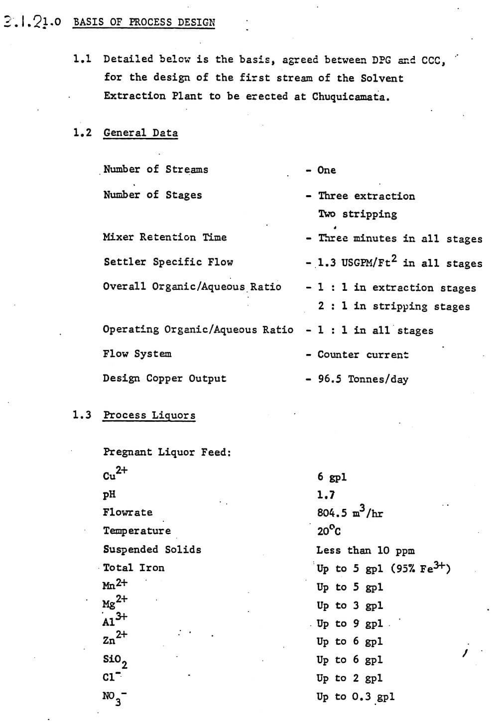
Table I and fig I give such a balance for the Chuquicamata commercial plant for reference only. The format of the calculation will obviously depend upon the type of system used.


Process Flowsheets
The following flowsheets are examples of the systems evaluated to date.
a) Chuquicamata
b) NCCK
c) T. Buttes
d) Butte
e) Luilu
Equipment Design
Mixer-Box
The essential details for a square mixer-box design are shown in Fig I
The required mixer-box volume is calculated from the total solution flowrate i.e aqueous + organic + recycle and the mixer-box retention time

Circular Mixer Bos:
Design as for a square mixer-box and calculate the diameter of a circle which would give the same area. The depth remains at 0.8W
d = 1.2155 (Vol.) 1/3 = 1.1283W
Impeller and Draught Tube

Double shrouded with eight backswept vanes


Inlet shroud = D/2
Shroud clearance = D/7
Radius of blades = D/√8
Shear blade heights (see figure 2 illustrating impeller configurations)
BB – no shear blades
CC2 – 2D/59
CC4 – 4D/59
DD3 – O – 3D/59 – Triangular shear blade
Impellor eye cone = 120° cone angle = 2D/21 cone height
It is a feature of the DPG design that the impeller should be located at the midpoint of the mixer-box. The responsibility for the detailed mechanical design of the impeller i.e. plate thickness, shaft diameter shaft and drive couplings is placed on the manufacturer.
Draught Tube
Diameter of draught tube = diameter of impeller/2 = D/2
The following recommendations for the impeller/draught tube clearance are made:


With draught tubes of greater than 0.6M diameter a ‘sacrificial’ sleeve i.e. viton A uPVC can be used to reduce the clearance between the draught tube and impellor to effectively zero and installed once the impeller is in position.

To minimise the head required of the mixer-impeller the standard DPG design can incorporate a concentric draught tube arrangement in which the light phase is normally fed to the eye of the impeller. This reduces the hydrostatic head required.
Anti-swirl vanes are fitted to the draught tube with a pitch/chord ratio of 1.5 to 2.0/1
Mixer Impeller Drive Units
The approximate tip speeds are advised for design purposes:
Pilot Plant:
All types impellers 600-1200 Ft/min
Full Scale Plant:
Type BB – 800-1200 ft/min
CC2 – 800-1000 ft/min
CC4 – 800-1000 ft/min
DD3 – 800-1000 ft/min
The attached specific performance curves are to be used for calculating the flow head and power characteristics of the various types of mixer-impellers.
Fig 3 Specific Head V Specific flow
Fig 4 Specific Power V Specific flow
Since the head delivered by the impeller is a function of the tip speed and independent of the S.G. of the fluid being pumped the heads as calculated from Fig. 3 will be translated directly to head of solution involved.
The absorbed power requirements are thought to be conservative giving rise to a possible 10% over-design factor. For design purposes, however it is assumed to be precise and since the graph is based on water the figures require correction by multiplying by the average S.G. of the solutions being pumped.
A sample calculation is given below.
Date Total solution feed (Q) to mix box = 6000 I GPM
Average S.G of solution feed = 1.1
Mixer-box size = 15.33 ft
Impeller type CC4
Impeller diameter (D) = 9.0 ft
Impeller tip speed = 1000 ft/min
Calculation Nrpm = 35.37
N r.p.s = 0.59
N3D2(r.p.s)3 (ft)2 = 16.64
N2D2(r.p.s)2 (ft)2 = 28.20
N3D5(r.p.s)3 (ft)5 = 12.127
N D3(r.p.s) (ft)3 = 430


Specific Flow Q/ND3 = 13.95
Specific Head N/N2D2 = 1.71
Specific Power P/N3D5 = 5.55
Hiead (inches water) = 48.22
Head (inches solution) = 48.22
Tower Ft lb/Sec (Water) = 67.305
Power Ft lb/Sec (Solution) = 74.035
Absorbed HP (Solution) = 135
Before the calculated figure for head could be accepted as a basis for design it must satisfy the pressure drop considerations dictated by the plant layout and piping details.
Fig 5 illustrates the hydrodynamic model for a mixer-settler from which the following system equations can be derived.


Notes
a. All heads have been corrected to equivalent head of dispersion
b. H4 is defined as the head loss in the draught tube, mixer box and top baffle.
c. The maximum pumping head requirement is imposed when the solution weirs are almost empty, i.e, h1¹, h2¹ and h3¹. Solution levels below these could result in our entrainment and subsequent loss of pumping performance due to air encapsulation on the eye of the impeller.
d. HV and HL can impose limitations upon equipment selection. The pressure drop that is available for dissipation across the control valve is usually small and care must be taken in selecting the type of valve whose characteristics enable satisfactory flow/pressure drop regulation during operation. Close liaison is therefore required between Process, Instruments and Piping Groups. Similar precaution is also required for flow indicators incorporated into the design since these can significantly alter the value of HL.
e. A reduction in impeller head requirements is obtained by using a concentric draught tube since the datum line is moved to the top of the draught tube.
Once the head requirement of the impeller is determined a series of calculations are required on head/power relationships as described previously. From there the type of impeller can be selected and defined in terms of operating speed and absorbed horse power needed. The type of drive can either be infinitely variable, or fixed with pulley change etc and the final selection should be assessed on progress, mechanical and economic considerations.
Design of Top Baffle
The essential details of the top baffle are shown in Fig 6 and should be used only as a basis for design. Reference should be made to previous designs and operating performances but the design should be evaluated for the particular system under investigation, i.e, satisfactory process requirements consistent with care of installation and subsequent maintenance.
The following points should be noted during the design stage:
a. The top plate of the baffle should be totally removable particularly it solid deposition is expected and the complete unit should be designed to be removable without disturbing the mixer-impeller drive unit.
b. A soft seal should be incorporated between the top baffle and the lining of the mixer-box to obviate by-pass, and fretting of the lining material.
c. The top plate of the baffle should be made as free as possible of surface projections, i.e, supporting and lifting lugs etc. Where these are essential they should be positioned to produce as little solution turbulence as possible.
Design Critera
The top baffle is installed in the top of the mixer-box at the 0.8Wlevel
Let W = width of mixer box
From scale up criteria in laboratories,
Diameter of bottom disc = 0.75 x W
Diameter of hole in top baffle = D/2


Picket Fence Design
DPG design to date has been to install two picket fences one just downstream of the introductory slot and the other upsteam of the organic weir. Experience from NCCM has indicated that the Front picket fence should be about 1½m beyond the slot and the back picket fence about 3m before the organic weir for this size of operation.
The information below indicates some of the different designs which have been used with regard to spacing.

The picket fences are normally about 50mm above the operating liquid level in the settler and are free swinging.
If crud formation is considered to be a major problem, i.e, results from pilot plant etc then the design should enable removal, particularly of the back picket fence for cleaning.
Head Loss
A head loss of 3″ of liquid should be allowed across the top bottle when calculating the power requirement of the impeller drive unit. A head-loss- check calculation should be carried out on the finalised design before commitment to manufacture.
Settler Design
Critical Velocity Criteria


Settler Area
Total dispersion feed, to settler = Q USGPM or M3/hr
Design Specific Settling flowrate = S USG/ft2/Min or M3/M2/hr
Then Settling Area required = Q/S
Knowing the minimum settler width allowable the effective settler length can be determined so that,
Le/Wmin is of the order of 2.5 to 3:1
NB
The effective settler length is the distance between the front face of the introductory slot and the leading edge of the organic weir.
Design of Weirs
a. Height
It is normal practice in DPG designs to attain the desired hydrodynamic balance in the settler by having an adjustable aqueous weir. Under these conditions the organic weir is normally fixed although it may be considered necessary to have some degree of adjustment for precise setting of its level following installation.

Following the determination of the weir under design conditions the effect of variations in Flowrate, SG of the solutions, organic and aqueous depths must be assessed. From this the adjustment considered necessary can be defined. The engineering tolerance should be taken into account during the final design.
Overflow Weir
For details of the determination of the height of the overflow weir refer to the process design calculations on Twin Buttes and NCCM Ltd (E Crisp.)
The overflow weir is located behind the aqueous weir and is designed to overflow aqueous only. In the extreme condition the maximum aqueous leg that can be balanced is,
Lo = Depth of settler x eo/eo
The crest height over the weir is calculated using the Francis formula. Then maximum height of overflow weir Lo-crest height.
However, consideration of the maximum permissible height in the mixer box is essential and, should be used in defining the height of the overflow weir. For the level in the mixer-box the height of liquid in the
settler can be determined (see Twin Butte calculations) and the level of the overflow weir will be the aqueous leg required to balance this value.
b. Depth and Width
Process requirement is basically the size of the outlet pipe. Liaison essential with Engineering Department on method of Construction. The hold up time in the weirs should be assessed when the final parameters are defined.
Both organic and aqueous weirs run the full width of the settler.
The width of the overflow weir to be defined by the process parameters.
c. Outlets
Where recycle is required two separate pipes should be used, one for the recycle and the other for the interstage line.
Vortex breakers should be installed in the outlet of the pipes from both the organic and aqueous weirs to reduce air entrainment.
d. Profiles
Refer to previous design work.
No standard DPG design is available and the previous work should be treated as a basis for future design. This is particularly true in the method for the aqueous weir adjustment.
Introductory Slot and Entry to Settler

The dispersion leaves the top hole in the top baffle and flows down into the distribution slot entering the settler via the introductory ports.
The width of the slot (X) is dependent on the total flow and its associated pressure drop.
It can be assumed that the worst condition as regards pressure drop is when the liquor turns through a 90° bend and travels the full width of the settler.
The assumption is made that the total flow is divided equally into two rates as shown above.
The slot was 24″ wide on the NCCM Ltd plant but operating experience indicated that this could be reduced; 18″ was used on the Chuquiccamata design.
As a generalisation the maximum head loss should be of the order of 1″ WG at a velocity of 1-1.5 ft/rec but these figures should only be taken as being indicative.
The flow of dispersion from the top hole of the baffle and its subsequent distribution to the slot is dependent on the magnitude of angle. This angle should be such that an even flow of dispersion is obtained with a minimum of dead area at the end of the settler. Liaison is required with both Civil and Engineering Groups to ensure that the process parameters are compatible with the engineering philosophy being adopted for erection and installation.
Slot Area and Number Off
The latest DPG design was installed on the Twin Buttes plant and is given for reference. The operating performance of this design should be obtained prior to future development work.
Apertures 150mm deep (this figure should be related to the dispersion bed depth) 375mm long 75mm spacing
By calculating the area of the slots and knowing the flow then the average velocity and pressure drop can be calculated (should be less than 1″ WG).
Positioning of Introductory Slots
Information required:
a. Static and subsequent dynamic levels of aqueous and organic
b. Thickness of dispersion bed depth and phase continuity (R&D Input)
c. Operating data from similar full scale plant designs, if available.
The effect of changes in organic and aqueous depths and phase continuity to be assessed before the design is finalised.


