Table of Contents
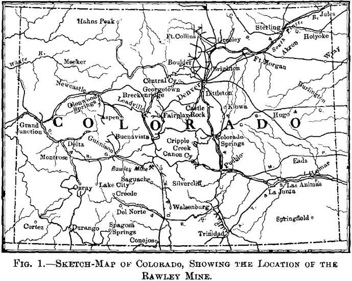
The Rawley property is located in the Kerber Creek mining-district, Saguache county, Colorado, at an elevation of 10,600 ft. (See sketch-map, Fig. 1.) Ore was found in this vicinity, and claims covering a large area were located and in many instances patented. The ores, however, being of comparatively low grade, and the nearest railway station, Villa Grove, being some 20 miles away, it is extremely doubtful whether any considerable amount of ore was ever handled at a profit.
About that time a very capable promoter gathered together a group of these claims and interested some New York people, who had had no previous mining experience, in the purchase of these claims. Following the organization of a company, this promoter became General Manager. As often happens under such conditions, the first step was to erect a mill to treat 100 tons per day. It may not be fair to this enterprise to say that the failure which followed might have been foretold, simply on general principles, but this much is certain—the water supply fluctuates in the course of a season through a wide range and for a considerable portion of the year was inadequate to run this mill at capacity. Further, it is currently reported that some of the mill foundations were placed on ice. However true this statement may be, it is a fact that, when first inspected by us, many of the belts in the mill were held on their pulleys by means of idlers. A shut-down followed, with a material re-adjustment of interests, at which time we became consulting engineers for the company.
The question which then confronted the owners was, briefly, whether to abandon the enterprise as a total loss, or to pursue a course of systematic development of the ore body as exposed by three short drifts.
Without committing themselves to an extensive policy of development, the stockholders finally decided to do a small amount of development-work—to put some money into the ground. Almost from the start, this work showed encouraging results in the way of blocking out ore of a satisfactory grade, although it was conducted during the next few years under many discouragements. Besides the natural difficulties of doing
work at such a distance from the railway, there were frequent labor disturbances, causing a shut-down, in one instance, of nearly two years. This brings to a time we had proved the vein to a depth of 600 ft,, and had developed in “ blocked out ” and “ probable ” ore. We found that the water was increasing at the rate of about 100 gal. per min. for each 100 ft. of added depth. Also, we found the character of the ore had changed, as we had anticipated in a report several years before, from a silver-lead-copper concentrating-ore in the upper levels, to a semi-pyritic silver-copper ore on the sixth level.
In view of the altered problem of mining and treatment which this new condition presented, we concluded that it would be very desirable to block out a large tonnage of this silver-copper ore, in order, first, to prove the average character of ore to be encountered with depth, and, second, to obtain ore to which the silver-copper concentrates derived from the silver-lead- copper ore of the upper levels could be added and more economically treated.
The following summary of the facts so far demonstrated by our work and study will aid to a more complete understanding of the problem which now confronted us :
1. The country-rock for several miles in each direction is of igneous origin, and all of strictly surface types—either tuffs, felsites, pumices, amygdaloids, simple andesites, or flowage-breccias. To the north, east and west, in various gulches, rock of this character is exposed at elevations of from 1,000 to 2,000 ft. lower than our 6th-level workings.
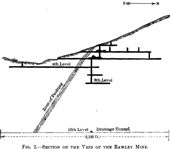
2. Across the country from east to west, cutting the Rawley vein nearly at right angles, is a zone of faulting some 50 ft. wide, dipping at an angle of about 55° S., as shown in Fig. 2.
This faulting was subsequent to the vein-formation, and the zone encloses, at various places, bunches of ore detached from the veins which it intersected. The lateral throw of this fault was slight, if any, but there is reason to believe that the vertical throw must have been considerable. However, no definite data existed at the time, and only meager data have since been developed to indicate the amount of this vertical displacement. There being but little lateral throw, the alignment of vertical or nearly vertical veins was only slightly disturbed by this faulted zone.
3. The Rawley vein is nearly vertical, extends in a general N-S. direction, and would undoubtedly be classed as a fissure. The walls are well defined, and no evidence of any fault, except the one above described, appears on the surface for a long distance on either side. The vein was developed more or less on six levels, as shown in Fig. 2.
4. We made many sections of the country-rock from various levels and from the surface for microscopical study. This work was done by Dr. Charles Berkey, of the Geological Department, Columbia University. Generally speaking, the rock consisted of a series of igneous flows. A very important point which we wished to determine was the general dip and strike of these flows. The difficulty of finding a true bedding-plane and distinguishing between it and a fracture was great. We finally obtained a sample of rock properly oriented on the ground, which gave us approximately this information. We also had many sections of the ore from various levels made for microscopic study. The results of this were very instructive, and
showed, first, that there was no indication of secondary enrichment, and, second, that the governing factor in the deposition of the minerals, as the evidence seemed to indicate, was the hydrostatic pressure of the mineralized water at different depths. Thus, galena predominated in the upper levels and gradually gave place to iron and copper as depth was obtained. Assuming this to be the correct theory, we reasoned that there was a probability of the increase of gold- and silver-values with greater depth. (We may here add that this has actually proved true. On the 12th level, the average gold- and silver-content has more than doubled.)
5. Surveys showed that the property was only about 6.5 miles in an air-line from a point on the railway at which an adequate water supply was found. According to careful estimates, Rawley ore could be handled at a good profit on a scale of from 200 to 300 tons per day to this point, and the ore blocked out above the 6th level would net considerably.
6. Surveys showed also that a tunnel some 6,200 ft. long would intersect the Rawley vein (if it was there) on the 12th level, 600 ft. below our lowest workings.
With the above facts as a basis, two courses were open: to continue sinking, or to drive a tunnel.
Several years’ experience in sinking, or trying to sink, had demonstrated that the cost of fuel and supplies was excessive, that the supply of labor for sinking a wet shaft was extremely fluctuating, as a rule inadequate, and always inefficient (good men do not have to locate in a remote camp); that pumping had to be continuous, whether progress was being made or not; in short, that the most liberal estimate for cost had to be multiplied by x to the nth power.
The alternative plan of driving a tunnel offered certain marked advantages. The cost of tunnel-driving could be estimated with a fair degree of accuracy; we were firmly convinced that the vein would be found in place, with perhaps a slight flattening towards the east; we were very sure that, if the vein were encountered, the upper workings would drain without the necessity of an up-raise; whether we encountered the vein or not, the decreased cost of developing and extracting the ore above, due mainly to the elimination of continuous pumping, would fully pay for the tunnel; and, finally, the tunnel would serve to develop certain veins, showing on the surface, in claims owned by the company along the proposed course.
The oft-repeated maxim, “ stick to your ore,” is to the mining engineer almost what the theory of the conservation of energy is to the mechanical engineer; and the members of the Institute can understand with what reluctance we finally advised our clients contrary to such a generally accepted and safe mode of procedure. However, we believed that at a stage in the development of a mining property such as we had reached, we were warranted, after having given long, close, and intelligent study to the characteristics of the ore deposit, in offering advice on economic grounds, without giving such overwhelming weight to the question of the continuity of the ore body. Realizing our great responsibility, however, we suggested the engagement of some prominent and unbiased engineer to go over all the facts and conditions which we could submit, and pass on our conclusions.
This suggestion was adopted, and, after careful deliberation, the engineer reported. His conclusions, which, unlike those of physicians in consultation, were adverse to ours on practically every important point, may be fairly summarized as follows: The rock-formation (igneous flows) would change at or before reaching the depth of 1,200 ft., and the vein would probably not be found at that depth, or, if found, would probably be barren, or of too low-grade to work at a profit; the tunnel would not drain the upper workings without a very expensive up-raise ; and altogether the risk was far too great to warrant so large an expenditure.
It is apprehended that these conclusions would have been approved by a large number of members of the Institute. It is not in any way a reflection on his recognized great ability, but only an illustration of the great difficulty that one engineer must find in giving due weight to the study and experience of another engineer, that he proved to be in error on every important point. The company finally assumed the risk of running the tunnel; and the results verified the correctness of our deductions.
Tunnel
Except the preliminary surveying and the placing of compressor-foundations, preparations for driving this tunnel began April 1, and actual work at the portal, May 7.
The first work was to establish, near the portal, camp-buildings suitable for the accommodation of from 30 to 50 men. In order to secure good men and keep them in a place like this, two things are very essential: clean, comfortable quarters; and an abundance of the best food obtainable. No reasonable expense was spared in order to meet these requirements.
In a general way we planned to locate the power house, black-smith shop, tool house, etc., as close to the portal as practicable, and so arranged as to involve the minimum amount of labor in handling steel, pipe, tools, etc. The bunk houses and boarding house were placed as nearly on a level with the portal as possible, and just so far away that the men when off shift could sleep undisturbed by the handling of steel, dumping of rock, and other noises. We may seem to be giving undue prominence to these little matters; but, in our opinion, attention to these and similar small details saved thousands of dollars during the course of the work.
The power plant consisted of one 80-h-p. return tubular boiler, with one 40-h-p. return tubular boiler in reserve; one Rand Imperial type No. 10 compressor (all of which were on hand); one No. 3 Roots blower (capacity 7.75 cu. ft. per rev.) direct connected to a 9- by 9-in. upright engine.
For drilling, we used two No. 8 Leyner drills, with crossbar, keeping one extra drill (and later on, two) in reserve, and maintaining also an abundance of extra parts always on hand. In the blacksmith shop we had one No. 2 Leyner steel-sharpening machine, operated by compressed air at 100 lb. pressure. Next to the steel-sharpener was placed a No. 8 Bradley coke-furnace for heating the steel, operated by a steam-driven turbine-blower, 12 in. in diameter, and furnishing at normal speed about 8 oz. pressure.
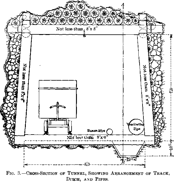
The cross-section of the tunnel was made 7 by 8 ft. in the clear, and where timbering was necessary the same dimensions were maintained inside the timbers. The arrangement of track, ditch, and pipes is shown in Fig. 3.
The grade of the tunnel was fixed at 0.5 per cent. For track, 18-in. gauge, 16-lb. steel rails were used, placed on ties 2.5 ft. apart from center to center. At frequent intervals, ties were placed across the ditch to support the pipes. Switches were provided at intervals of about 1,500 ft. for the passage and storage of cars. For fuel, wood was purchased from the Forest Reserve, at points so located that the haul to the tunnel portal would be down-grade. For blasting, 40 per cent, dynamite was used almost exclusively.
The tram cars used were 4 by 2 by 2 ft., body of 0.25-in. steel, with double bottoms, boxes reinforced around rims and centers with 0.5- by 2-in. steel, and with turn-table dump, mounted on chilled iron wheels. The cars had a continuous draw-bar and were coupled by means of three long links, giving considerable slack for facilitating the starting of a train. Mules were used for tramming, and by reason of this slack between the cars, one mule could start a train of 8 or 10 cars.
The labor for this work was organized as follows:

The above gives a fair representation of the working-force, and, with uniform rock-formation, little change in number or arrangement would be required. Unfortunately, however, the rock proved to be anything but uniform. At any moment, the andesite might change from a very soft material, full of slips, and requiring to be timbered close to the face, to a very tough, hard rock, highly silicified. This silicified rock, largely jasper, carried sometimes 30 per cent, of pyrite, and would eat up steel faster than the blacksmith could get it sharpened. For instance : one day so much muck would be brought down that we could not put muckers enough in the tunnel to get it out on time, while, perhaps, on the next day, two or three muckers per shift would be ample.
This irregularity of the rock-formation had far-reaching effects. By reason of it, no system of drill-holes was possible, and, from day to day, each shift had to lay out the holes in such a way as seemed best to the foreman or the shift-boss.
Moreover, in the use of powder, no attempt could be made to determine a point of maximum efficiency, as would have been possible with uniform ground.
The sequence in the operations of driving the tunnel, when everything was in proper running order, was about as follows: Just before shooting, the compressed air was turned on through a small nozzle pointed directly at the place where the muck pile would be. At the same time the blower was speeded
up. After a round had been fired, the blower cleared the air by suction from the face sufficiently to allow the men to begin work, an operation requiring about 20 min. The foreman and drill-men would then begin picking down roof and face. When the roof was in a safe condition, the drillers, or helpers, would “ muck back ” sufficiently to allow the bar to be set up in its upper position. This mucking, as a rule, took a few minutes only, and simply amounted to trimming off the top of the muck pile. During this time and while the bar was being set up, helpers would be connecting up hose and muckers bringing up empty cars. The hose was never allowed to lie along the bottom of the tunnel and on the muck pile, where it would be constantly exposed to damage, and would interfere more or less with the mucking. To avoid this we put near the roof, at frequent intervals, cross-pieces over which the hose was hung. The cross-pieces consisted of two pieces of pipe, telescoped, and with a set-screw, permitting them to be put up and taken down with great facility. In order to have the bar set up each time at the same height above the grade-line of the tunnel, iron hangers were hung from the last two survey points, for example, 100 and 300 ft. from the face, respectively. By means of wire at the top, these hangers were adjustable; and, as a hanger was moved forward to a new station, its length was calculated exactly, so that its bottom, shaped like a stirrup and carrying a candle, would be at the same height above the grade-line as the bar was required to be set. As the survey points were exactly along the center-line of the roof, the foreman, by standing back and sighting towards the face, could, in about a minute, signal to the driller at the face both the center-line and the height at which to set the bar. This operation was performed before each set-up, and no difficulty was experienced in keeping the alignment and grade almost perfect.
As soon as the condition of smoke permitted, mucking began. The sequence of the various operations of mucking was about as follows:
Empty train arrived and was pulled as near to muck pile as practicable.
Empties were turned on sides.
Down-tunnel end-car of empties righted on track, and pushed to muck pile.
Mucking began.
Full car pushed down beyond last empty.
Next empty car righted and pushed to muck pile.
Same order as above was followed, until train of empties was all loaded.
Another train of empties arrived and was hauled to a short distance from loaded train.
Mule was detached from train of empties and hauled loaded train hack towards muck pile as far as practicable.
Train of empties was hauled as near loaded train as practicable.
Empty train was turned over on side.
Loaded train started for portal.
The foregoing data give the full cycle of events as regards mucking; but perhaps a few additional remarks may be appropriate. When the rock breaks well, and the advance is regular and rapid, the rate of advance becomes a question of disposing of the muck. Hence the system as above outlined must be carried out with almost mechanical precision. It is here that attention
to small details is of great importance. Consider, for instance, the question of whether men are right-handed or left-handed. Suppose you have four men shoveling into the car. The ideal condition in that case is to have two right-handed and two left-handed men. Located so far from an adequate labor supply,
we found it, at times, impossible to fulfill this condition ; but it was constantly kept in mind when employing new men.
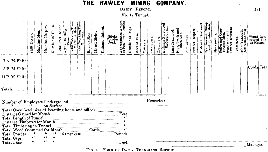
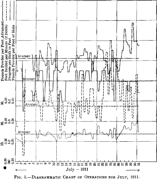
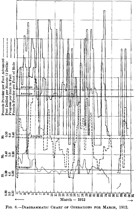
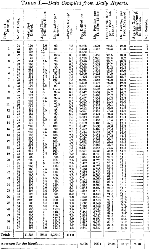
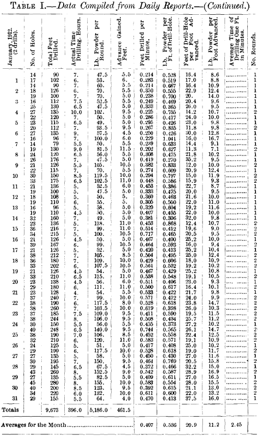
Beginning June 14, 1911, and continuing throughout the course of the work, a daily report, shown in Fig. 4, was sent to the New York office. From these daily reports various details were calculated and the data tabulated for each month. As 17 months of these tabulated data seems an unnecessary mass of figures to present, we have selected the months of July, 1911, and January, March and July, 1912, as representing typical periods under varying conditions. (See Table I.) In addition, we present the totals and averages for all the months. (See Table II.) From the tabulated data for July, 1911, and March, 1912, was made the efficiency-chart, Figs. 5 and 6. It is with regret that we call attention to the omission of one item that could easily have been supplied, viz.: The number of drills dulled per round. However, after the work was under way and some little time had gone by, we did not like to introduce a new item into the already lengthy daily report.
As hereafter explained, we used, after March, 1912, three full shifts in driving the tunnel. In tabulating the data for a continuous chart, we combined the results of two shifts in order to maintain the uniformity of our chart. A simple inspection will show, as a rule, where this combination is made. Of course, the chart does not really show anything more than the figures show, but, from an examination of the chart, one can see better at a glance the relation of the various factors given.
It was our idea to have one line on our chart represent, if we may use the expression, the “ tunneling quality ” of the rock. For this purpose we had a record kept of the data which would permit us to calculate, for each round of holes, the distance in feet drilled per minute. Of course this is only one of many factors that would be necessary in order truly to represent “tunneling quality.” We believe equally good data to represent this line could have been obtained by keeping a record of the number of feet drilled per round, and the number of drills dulled per round, with the advantage of possibly greater accuracy in the record. However, it is interesting to note that the months when our average in “ Feet drilled per Minute ” was high, were quite uniformly good months, both in progress and general efficiency.
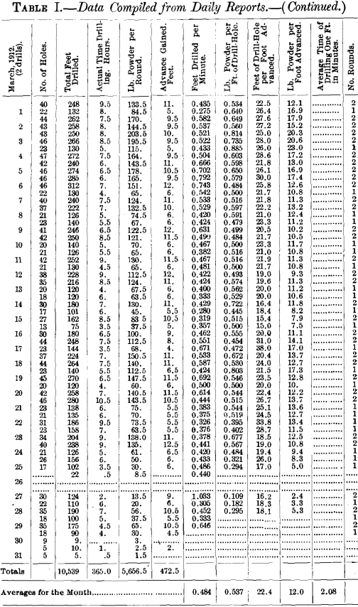
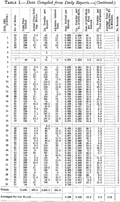
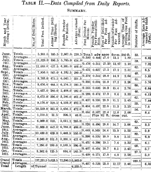
The other lines on the chart, “ Pounds of Powder per Foot Advanced,” “Advance Gained,” and “Pounds of Powder per Foot of Drill-Hole,” were made, not only for our own study and information, but quite as much to encourage the men to be economical in the use of powder, and incite them to rivalry in the “Advance Gained per Shift.” We have introduced isolated charts for two typical months only, because the continuous chart from the beginning of the tunnel to the end is about 9 ft. long and consequently seemed too long for convenient publication. (See Figs. 5 and 6.)
At first we operated on the basis of two 8-hr. shifts per day. Each shift drilled one full round with the view of “ pulling ” 8 ft. While following this plan our best month was July, 1911, in which our progress was 414 ft. We have taken this month, therefore, as typical of the most successful operation of the method. It will be seen that the maximum progress in any day was 15.5 ft.; and it is safe to conclude that more than 16 ft. was not possible.
With the view of devising a method which would at least render possible a greater progress per two shifts, we studied the problem carefully, on the basis of the data already obtained (such as the average feet drilled per minute, etc.), and came to the conclusion that two drillers and helpers, in good drilling- ground, could put in two rounds of from 4.5 to 5.5 ft. in one 8-hr. shift, which would make it possible under favorable conditions to advance from 18 to 22 ft. per day. The work of mucking under this method would be very much facilitated, because fully 25 per cent, more muck could be landed on the muck-plates, and, if necessary, a third shift of muckers could be used.
It is one thing to lay out a carefully worked out plan, but it may be very difficult to inaugurate the plan under favorable auspices. A good plan may easily fail by not having the enthusiastic support of the men essential to its success.
The following statement of the progress per month shows that September, October, November, and December were comparatively poor months. This was in part due to very difficult ground, containing a large amount of the jasper before mentioned. Nevertheless, in our opinion, a much better record could have been made had the plan of short rounds been adopted during this time.
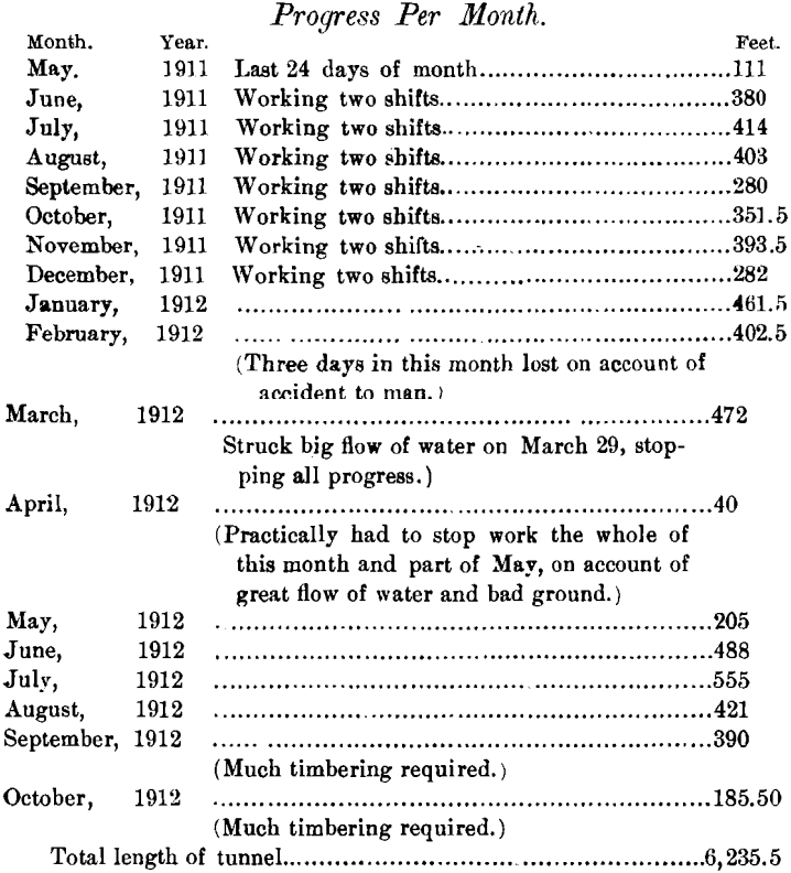
The tunnel reached the vein on Oct. 23 at a point 4 ft. from our calculation.
There was no favorable opportunity for trying out the plan of shorter rounds until Dec. 22, 1911. On that date we advanced 21 ft.; and, after this demonstration of the possibilities of the plan, there was no further trouble in putting it in force.
In applying this method, we found that the drill-men on an 8-hr. shift had to work overtime on an average of perhaps 1 hr., for which they were paid an extra amount. The drill-men and their helpers were glad to get this overtime. We found that with this method, in fairly good ground, two 8-hr. shifts of drill-men could pull as much ground as three 8-hr. shifts of muckers could handle. The method produced very efficient results all along the line. But we were not long permitted to derive benefit from it. Towards the end of March, we were notified by our attorney that a late decision of the Colorado courts made the working of men longer than 8 hr. (even though desired by the men) an offense punishable by fine and imprisonment. This had very much the appearance of putting a premium on inefficiency, for we were forced to employ two extra drill-men and helpers for 8 hr. in order to do 2 hr. work. This is the law in a State which, during the past few years, has been loud in its lamentations over the decline of mining. Under this mandatory condition, we could gain little, if any, efficiency and economy over our original method.
Towards the latter part of March, as noted in the foregoing statement of progress, a large flow of water was encountered, which almost stopped our progress for about six weeks.
This sudden influx of water was interesting, but very expensive. About Mar. 25 we struck the zone of faulting mentioned in the early part of this paper and shown on Fig. 2. In this zone the rock is full of slips and very much ground up. The tunnel was perfectly dry for a distance of about 40 ft. in this formation. On Mar. 29, a round of holes was put in, the bottom of each hole being perfectly dry. When this round was fired a flood of water came with it. The ground-up material of this formation seemed to disintegrate in contact with water and filled the entire face of the tunnel. It was roughly estimated that the volume of water amounted to more than 1,000 gal. per min. After trying in vain to catch up the ground at the face, the Superintendent came back about 50 ft. in the tunnel, and started a cross-cut at an angle to encounter the water some distance from the face, and thus divert the flow, or most of it, from the main tunnel. This plan succeeded; enough water was diverted to enable us to proceed with the driving of the main tunnel, although for many weeks it was only with the greatest effort that any progress whatever was made.
There is an interesting feature in connection with this matter, outside of the difficulties in the prosecution of the work. As we understand it, the zone of faulting constituted in effect a water-tight dam. Penetrating this dam with the tunnel, a point was finally reached where the pressure of water broke down the barrier remaining. That there was an actual hydraulic pressure back of this zone, seems to be clearly indicated by the fact that after several weeks of flow the force of the incoming water grew very rapidly less, and within a short time the flow became quite negligible.
No serious difficulty was encountered during the construction of the remainder of the tunnel, but progress during the latter part of August and during September and October, 1912, was much impeded by reason of the timbering required.
The maximum advance for any one month was 555 ft., made in July, 1912. However, we were forced, as already remarked, to use three full shifts of drillers as well as muckers during that month, and so do not consider that it equaled in economy and efficiency either January, February, or March; during which months two shifts of drillers were used.
We were much in error in our original estimate of the amount of timbering that would be required. All told, it was necessary to timber 1,618 ft., most of which required full sets, instead of only 500 ft., as we had expected. Moreover, much of the timbering in August, September and October, 1912, had to be done so close to the face as to hinder seriously, and at times entirely stop, the progress.
Summary of Costs
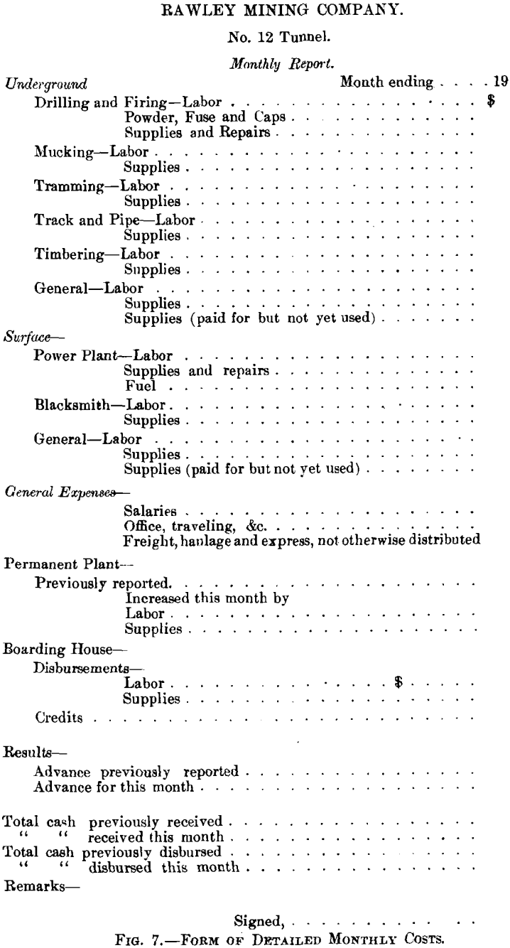
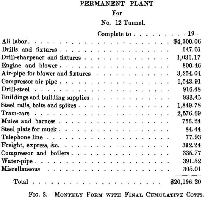
Each month, as the work progressed, we had two forms filled out, as shown in Figs. 7 and 8.
Form No. 1, Fig. 7, gives the detailed costs; Form No. 2, Fig. 8, the costs chargeable to the permanent plant. There were two reasons for keeping the record in this way. In the first place, bills for the various items under “ Permanent Plant ” came in very irregularly, and would have greatly delayed making out the monthly cost-sheet. In the second place, it was convenient in the end to have the various items of the “ Permanent Plant ” kept separate, so that the apparatus and material could be charged back to the general mine-equipment at a proper figure. We have charged back in this way the following items at 50 per cent, of their cost:
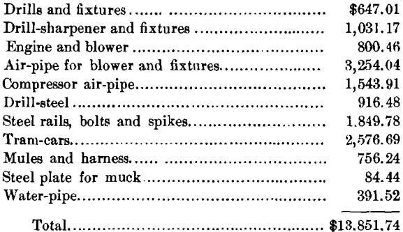
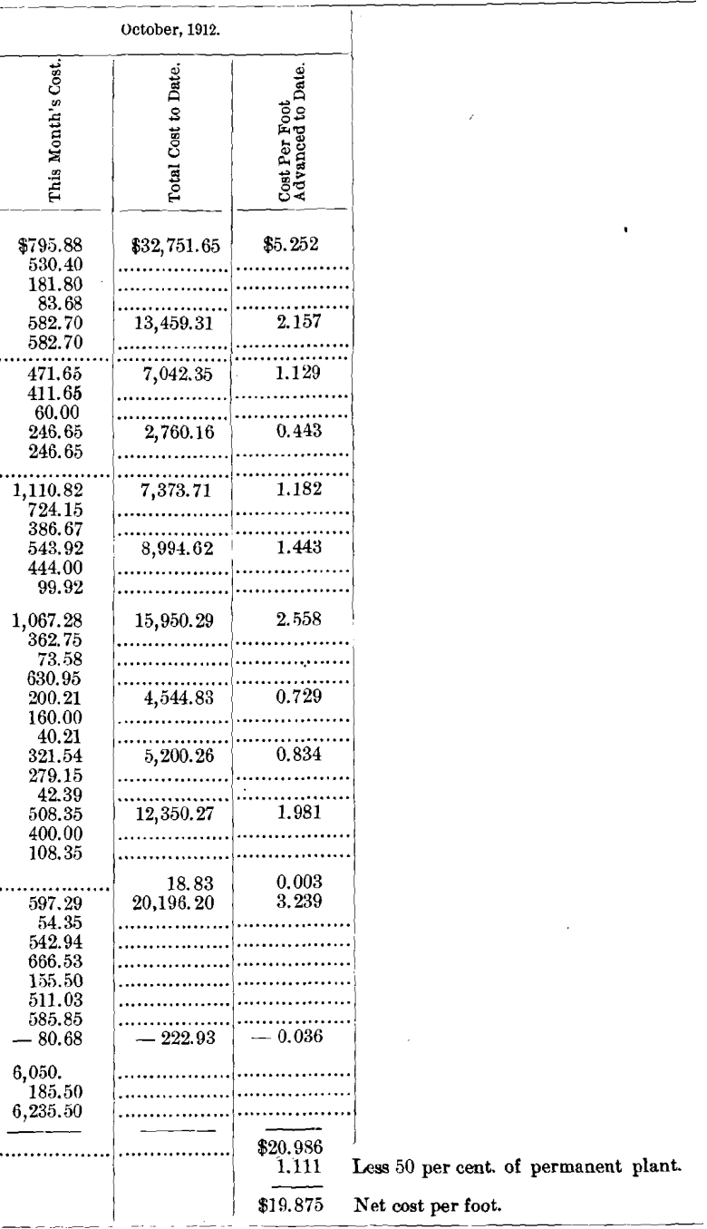
Taking 50 per cent, of the $13,851.74 above given and which represents that part of the permanent plant to be salvaged, and dividing by 6,235.5, the length of the tunnel, we have $1,111 to take from the total cost of $20,986 per ft. of the tunnel, making the actual cost per ft. $19,875.
Our original estimate on the cost of driving this tunnel was $21.12 per ft. After deciding to construct the tunnel, we prepared plans and specifications, and advertised for bids. The lowest responsible bid received was $26.50 per ft., and this did not include the timbering.
From the monthly cost-sheets given above we have made up the complete and cumulative statement of costs which follows. The arrangement of this statement of costs can be most clearly understood by an example. Taking the month of June, 1911, it will be seen that “ This Month’s Cost ” for “ Drilling and firing” is $2,160.49. This figure is the sum of the “ Labor,” “ Powder, fuse and caps ” and “ Supplies and repairs,” set immediately below the $2,160.49. Under “ Total Cost to Date ” the $2,921.88 is the sum of the $2,160.49 and $761.89, the “ Total Cost to Date ” of May. The “ Cost per Foot Advanced to Date,” $5,951, is obtained by dividing the “ Total Cost to Date,” $2,921.88, by 491 ft., the “ Total advance.” The figures for “ Mucking,” “ Tramming,” etc., are arranged in a similar manner.
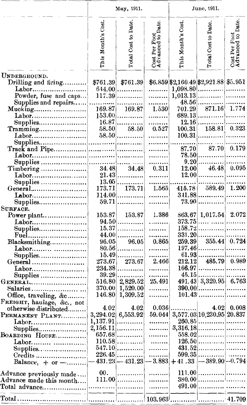
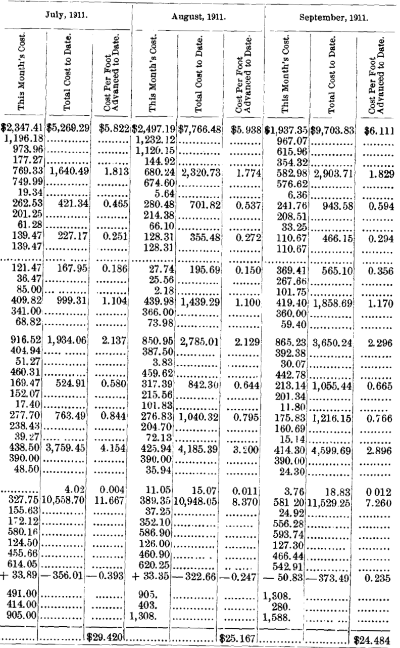
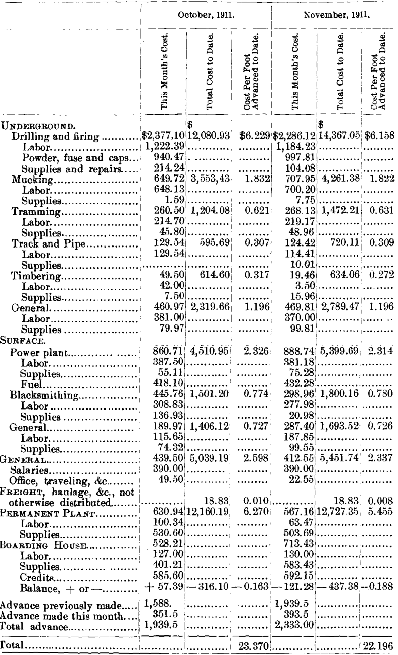
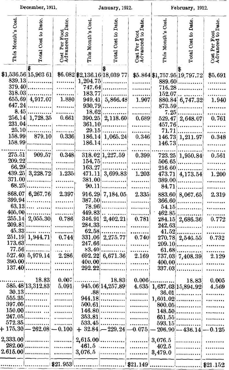
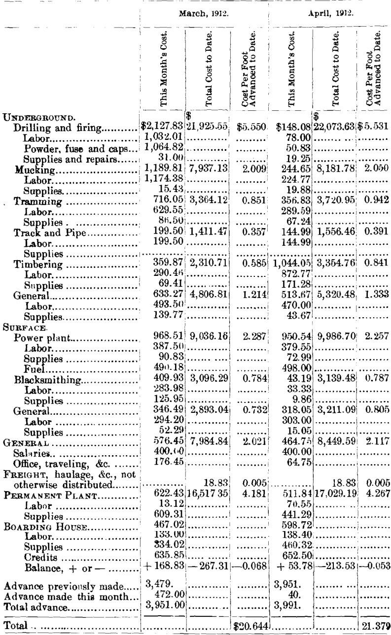
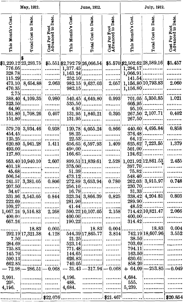
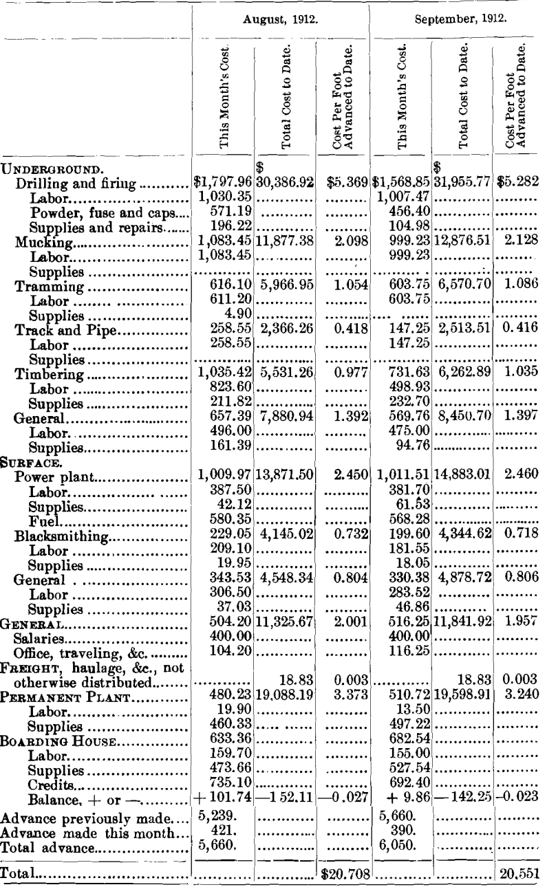
It is to be noted in analyzing these figures that there are some seeming inconsistencies. For instance, the cost of mucking gradually increased throughout the course of the work. Theoretically there should be no difference in the cost of shoveling rock into a car whether it is 5,000 ft. from the portal or 500 ft. The explanation for this increase is threefold: first, the labor cannot be maintained in exact ratio to the progress (if three men can muck a maximum of 8 ft. per shift, four men must be used to muck 9 ft.); second, if the tunnel breaks large there is more muck per foot advanced, and the cost per foot increases; finally, the efficiency of the mucking crew decreased, in our opinion, for various reasons, as the work progressed.
Another apparent inconsistency is the gradually-increased cost of track- and pipe-work. This was very probably due to the fact that with every foot advanced there was 1 ft, more of track, pipe, and ditch to maintain and keep in repair.
We submit the foregoing discussion of the mining problem, together with the complete data regarding the driving of the tunnel, in the hope that it will have value to those who maybe confronted in the future with somewhat similar situations. As regards the tunneling data, we have tried to make them complete, and consequently it is a record of unsatisfactory as well as satisfactory results. We trust it may serve both as a warning against uneconomical methods, and as an aid to securing greater efficiency in work of this character.
In conclusion, we wish to pay a deserved tribute to the men whose labors contributed in large measure to any success attained. No more fitting comment can be made than the statement that the work throughout was delayed less than 80 min. on account of trouble with the power-plant, and this statement simply illustrates the efficient service rendered in every department. To Will C. Russell, who had charge of this work, and to Charles E. Beckwith, his assistant, unstinted praise is due for their unflagging zeal, fidelity, and vigilance.
Discussion
W. L. Saunders, New York, N. Y.:—Mr. Burns in his native Colorado modesty has said that he apologizes for things left out of this paper. I am much impressed by what he has put into the paper, as of all the papers that I have read on the subject, describing, as it does, a specific piece of work that has been accomplished, I do not recall one that gives so much information in such a practical way. Mr. Burns has also said that it is very hard to get men to put things down while the work is being driven. My experience is that it is very much harder to get the men in charge of work of this kind to bring them in the form of a report before a body of engineers after the work is done. We have a great many cases where records are kept in much detail, but they are usually kept under cover, with the mistaken idea that the information gained is private information for the benefit of those who have done the work. Messrs. Simonds and Burns have opened up this case so that we can get the benefit of that experience which they have had, and so that we can learn something for the future.
The description contained in this paper, as I have said, is a very practical one. You will notice in going through it that the authors have given in detail a record of their work from the beginning to the end, and they even go so far as to publish an exact copy of the Rawley Mining Co.’s daily report. That daily report is something which those of us who are engaged in similar work might copy to great advantage, and having it before us we can check up our men while doing work and exact from them equal conditions, if it is possible to do so.
The dimensions of this tunnel are 7 ft. high by 8 ft. wide, with a length of a little over 6,000 ft., so you see we have here a typical mining tunnel, a little over one mile long, and with the usual dimensions of 7 by 8 ft. The best monthly progress, firing from 8- to 12-ft. rounds, was 414 ft., and the best monthly progress for the shallow rounds, from 4.5 to 5.5 ft., amounted to 555 ft. I want to call particular attention to that statement, and those of you who have read the paper will see that when they changed from a double shift to a triple shift, putting in shallow holes, they got better progress. The shallow hole idea is the European idea, it is the Alpine tunnel idea, it is the idea by which engineers have carried through those great enterprises of piercing the Alps, in the case of the Simplon tunnel and the Arlberg and the Loetschberg tunnels. These recent tunnels which have been put through the Alps have all been driven on the shallow hole plan; in other words, a hole is put in about a meter or a little more than a meter in depth, and of rather large diameter, as compared with the American system, which is, a hole as large as you can reasonably get it, and that means, by the time it is in to the bottom, say 10, 12, or 14 ft., it is just a little larger than the diameter of the steel, the result being that you are putting the explosive at the bottom in a section of hole of small diameter, which is the very reverse of what is wanted in order to produce the most effective results. It is much better—and this is a point that I have emphasized before the Institute in papers in the past years—to put in a large number of shallow holes of large diameter and use a great deal of powder than to put in a small number of deep holes and try to save powder and try to be very particular about the exact direction that the hole must take. The European system simply peppers the head with holes, and better results are obtained by that method.
The total cost per foot of advance in the completed tunnel was $19.87. That is a very fair figure, and less than the estimate of cost made before this tunnel was driven. The average total cost per cubic yard excavated was $7.64. That may seem high to some of us, but if you go over the figures of labor cost in this paper you will see that the wages are higher. The people employed on this work evidently were compelled to pay a maximum rate of wages for this class of work, and, taking that into consideration, the figures are not high. The average number of feet of hole per drill per drill-hour was 12.2. The average inches per drill per minute was 2.5. The approximate yardage per foot of advance, allowing for 25 per cent, of over-breakage and swelling, was 2.6 yards, or a cost of $7.64 per cubic yard. In all of this we must take into consideration the difficult rock which was encountered and the water troubles which they had; yet, comparing the progress of this tunnel with that of any of the recent tunnels of which we have records, the progress appears to be very favorable. The most recent of these records was made at the Arizona Copper Co.’s mines at Morenci, Ariz., the tunnel being 8 by 9 ft., where 780 ft. advance was made in 29 days, employing two C-110 drills mounted upon a cross-bar. We also have the record of the Laramie tunnel, in Colorado, which is similar to this one except that it has a ragged section. It is nothing but a hole, without any specified dimensions of outline, but it serves its purpose very well as a drainage tunnel. Being ragged, it enabled progress to be made in excess of that given in this paper.
Now, the description of the process of driving tells us that this tunnel was driven by the system of mounting the drills on a horizontal cross-bar across the tunnel. Here we have a thoroughly modern system; the same, by the way, as was used at the Laramie tunnel. In the American system of tunnel-driving vertical columns with arms on them are usually employed. The European system of tunnel-driving is one in which horizontal bars mounted on carriages are employed. The system described in this paper is neither one nor the other, but the drillers used a horizontal bar without any carriage; in other words, they adopted the Alpine system of tunnel-driving, but did away with the carriage. Now, they were able to do away with the carriage because they used hammer drills instead of piston drills in the headings. The piston drill is a machine which reciprocates and which creates a great deal of shock on its mounting, necessitating a very heavy bar or column. The machine itself is heavy, and necessitates the use of either the carriage system or the vertical column with arms.
It appears that those who drove this tunnel used the hammer drill, which is lighter in weight and does not give the jarring and reciprocation, hence they were able to use a light bar, which a few men in the heading can handle to advantage. This light bar is carried on top of the muck pile after the blast and jacked in place close to the roof; the drills are put on and put in operation; the men work the drills standing on top of the muck, the muckers being at work at the same time in digging away the muck underneath them. By the time the muck is largely removed the drillers are about ready to let the bar down, and just about that time the muck has been taken away, so that if necessary the bar can be placed in a lower position in order to put in the lower round of holes, if these cannot be drilled from a single setting of the cross-bar. By such a system as this they were able to make a progress, I believe, of 26 ft. per day; in other words, a little more than 1 ft. an hour during all of the 24 hours in the day. That, of course, is not the record. The Alpine system has made about 30 ft. per day, and in the Laramie tunnel they made something like 24 ft. a day. Comparing progress of this character, however, we must always take the character of the rock into consideration; also the length of the tunnel. The Alpine tunnels are longer tunnels, and, by adopting a certain system and carrying it out for a long period of time, it was possible to get the efficiency of the workers very high.
The engineers in this tunnel decided that better results could be obtained by drilling shallow holes and operating three shifts per day. This plan was put into effect in December, 1911, and, as I understand from reading the paper, it proved to be very efficient. The results, as given in the table printed in the paper, show that the average number of feet of hole per drill per drilling hour was 12.2. This is good, but not remarkable, as it involves only approximately 2.5 in. per min. Of course, the rock conditions govern this. On page 171 reference is made to the results obtained in the entire equipment of the tunnel.
This subject is one which is very active at the present time, because American engineers are adopting a system of tunnel-driving which is to a certain extent a cross between the European and the old American system, but which has, I think, a great many points of advantage over both of them.
The Chairman :—May I ask, when the tunnel got to the vein did it satisfactorily drain out all the water, or did the water go down through the vein itself or through the false zone outside ?
Mr. Burns :—We reached the vein on Oct. 23, but we did not have to wait to know that it would drain; the influx of water informed us of that. The upper levels drained in about 30 days.
The Chairman : — There was an open connection right through the tunnel ?
Mr. Burns :—Yes.
Prof. Henry S. Munroe, New York, N. Y.:—I hope the authors will supplement this paper with additional details regarding the method of ventilation employed. I note that they used a rather small pipe for so long a tunnel. From the scale of the drawing I should judge it was about 12 in. in diameter. It appears also that the heading was ventilated by exhaust instead of by pressure, and that they used a Roots blower, indicating that a high water-gauge was employed.
As the use of auxiliary fans is common in mines, and as we have little information as to the working results, I hope that the authors can give us some idea as to the leakage in this long pipe; and as to the type of joint used, with the method of calking or wrapping, or the precautions taken to lessen leakage. It would be of interest to know the actual amount of air entering the pipe at the face of the tunnel as compared with that discharged by the fan; also, the water-gauge at the fan, the number of revolutions necessary, and the horse-power required.
It would be of interest also, as bearing on the relation between diameter and thickness of metal, to know whether the air pressure from heavy blasts tended to collapse the pipe, how near to the face the pipe was laid, and whether suction was efficient in removing the powder smoke quickly after a blast.
Mr. Burns :—I think I can furnish a good deal of the data that Professor Munroe asks for. The information he desires is among those things we did not give and is, perhaps, conspicuous by its absence from our paper. We got good results. To show the volume of air which our blower sucked out, I can say that in 20 min. our heading was clear of smoke, so that the men could go in and go to work. That was the practical thing that we were looking for, and possibly we overlooked making as careful records in regard to work of that character as we otherwise should have done. We got the results, and that was our chief object.
Now, this much is certain: our pipe work was done pretty well. I think if there had been any very serious leakage in our pipe it would have been discovered very soon. A leakage 1,000 ft. from the portal, when we were in 5,000 ft., would not have had to be very large in order to interfere seriously with sucking the smoke out rapidly and efficiently, and our men who repaired the pipes and took care of the track were constantly on the lookout for any leakage and immediately repaired it. A serious leak would become quite evident on account of the noise made; and further, our men carried their lights along the pipe, and a leak of any kind was very soon discovered.
At this time I wish to call attention to the cost data which we give on the track and pipe work: You will notice that the track and pipe expense shows a gradual increase from the first month to the end. At first I was puzzled to know why that should be, but I believe that it was because every foot of pipe and track completed became just that much more to keep in repair.
Messrs. Simonds and Burns (communication to the Secretary):—In response to certain suggestions by Prof. H. S. Munroe, we take pleasure in submitting the following details:
The ventilation pipe consisted of No. 18 U. S. standard gauge, riveted steel, coated with asphalt, 12 and 18 in. diameter, in lengths of about 20 ft. Slip joints with lugs were used, and tar paint was used on all joints. It was only occasionally necessary to use the lugs, in which event bailing wire was looped around the lugs and twisted till the necessary tension was produced. In case any leak developed in a joint a thick layer of tar paint was spread on a strip of canvas and bound tightly over the joint.
It was occasionally necessary to remove a length of the ventilation pipe either on account of damage from falling rock or because timbering became necessary. In order to provide for this contingency lengths of flanged pipe were put in every few hundred feet.
The reason for using two sizes of pipe was that, in shipping, the pipes could be “ nested,” and consequently not only save freight but somewhat lessen the liability to damage.
It is quite probable that for a permanent length of 6,000 ft. a ventilating pipe 12 in. in diameter would not be the efficient size to adopt, cost of pipe and cost of fuel properly considered, but it must be remembered that the distance was not 6,000 ft. but zero to 6,000 ft. Anticipating an extra demand on both engine and blower as the tunnel neared its maximum length, we provided in the beginning an engine 9 by 9 in., instead of the 8 by 8 in. engine more commonly supplied by the manufacturers for this size blower.
It may be of interest to discuss this problem of ventilation from an initial point of view—whether to ventilate by “ pressure ” or “ exhaust: ”
So far as the question involves the operation of the engine and blower, either method could be adopted, but it is far different when the question of installing and operating the pipe is taken into account. The pipe when operating under exhaust can be installed much more rapidly because very little care is required in order to make tight joints. In case leaks develop at the joints the defect can be easily and quickly remedied; in fact, this is true of almost any damage that is likely to occur, such as the penetrating of the pipe by the sharp corner of a rock or the sharp point of a pick. No tendency in the pipe to collapse appeared at any time either from the exhaust pressure or from the effect of blasting. Practically no damage of any kind occurred to the pipe except as the result of falling rock, and this, considering the treacherous nature of much of the ground, was of infrequent occurrence.
Finally, considering the question from the standpoint of the results to be accomplished,—viz., the removal of the noxious gases in the least possible time,—the reasons seem to be very conclusively favorable to the suction method, at least after the face of the tunnel has reached a point about 1,000 ft. from the portal. Whichever method is employed, the pipe cannot safely be carried much closer to the face than 150 ft. In either case, also, just before blasting, the compressed air nozzle would be placed some 35 ft. from the face, pointing directly thereat, and the air turned on. This not only stirs up the gases at the face but quite rapidly forces them towards the ventilating pipe. In case of a suction pipe this action is accelerated, but in case of a pressure pipe the action would be retarded. Assume, for instance, that the tunnel is in 6,000 ft. and that the blower has a capacity of 8 cu. ft. per rev., or 2,400 cu. ft. per min. Under this condition it took rather less than 20 min. to suck practically all the noxious gases from the face. In 20 min., at the above rate, 48,000 cu. ft. would be removed, and this corresponds to the removal of air (expansion, contraction, and compressed air not considered) from 860 ft. of the tunnel. Comparing this with the pressure method under similar conditions, if the incoming air from the blower could immediately collect the noxious gases in a body and push them towards the portal it would take (expansion, contraction, and compressed air not considered) some 2.5 hr. to remove them from the tunnel. Of course in this latter case there would result a gradual mixing of the air and gases, making the same breathable but probably not very healthy.
Following out suggestions made by Professor Munroe, we have had some measurements made of velocity of air and vacuum produced by the fan. The pipe was partly dismantled, but 4,650 ft., measured from the blower, was still in place. Making correction for error in the anemometer readings, the velocity of air obtained was approximately 3,000 ft. per min. at inlet and discharge, at 300 rev. per min. of the fan. The vacuum at the fan was 2.5 lb. From this data a rough calculation makes the theoretical velocity about 2,800 ft. per min. Water is discharged with the air at the outlet, making it impracticable to measure the velocity accurately, but the leakage is apparently negligible.
The comments by Mr. Saunders are interesting, and particularly gratifying to us in one respect—the facility with which he has transformed our data into other terms for the purpose of consideration and discussion. This was one special object which we had in view, viz., to give the data so completely and specifically that engineers could use the same for estimates and comparison free from doubt as to the inclusiveness of any particular item.
We are of the opinion that Mr. Saunders was either under a misapprehension in one respect, or inadvertently misstated himself. We refer to the statement “ that when they changed from a double shift to a triple shift, putting in shallow holes, they got better progress.” Of course we naturally would have secured better progress with a triple shift, but what we particularly wished to emphasize was the fact that when we changed from a double shift using long holes to a double shift using shallow holes, but with three shifts of muckers, we secured better progress and greater efficiency. The maximum progress possible, as pointed out, with a double shift using long holes was 16 ft., while with a double shift using shallow holes 19 ft. and over was not at all unusual, as shown by the following record:


