Table of Contents
In open pit mine planning, the design of the most profitable ultimate pit limit is a prerequisite to developing a feasible mining sequence. Presently, the design of an ultimate pit is achieved through a computer program in most of the mining companies. 3-D block model is commonly applied to represent geologic and economic information of an orebody. Once the deposit is divided into rectangular blocks by constructing a three dimensional grid, a grade extension technique is used to extend drill hole assays to each block. A block is classified as either ore or waste according to its net value obtained from mining. A block is considered as a possible ore block if the profit value of that block is positive. Otherwise, the block is considered as a waste block.
The algorithm assures to produce a true optimal solution to a 3-D mine model. The algorithm formulates the 3-D block model into a directed graph consisting of many trees. The vertices in the graph are equated to the blocks in the mine model and the imposed arcs in the graph represent pit slope constraints. Arcs are only generated between either ore to waste vertices or waste to ore vertices. No arcs are generated between the ore vertices nor between the waste vertices. Each directed arc which points from an ore vertex to an overlying waste vertex or points from a waste vertex to an underlying ore vertex indicates that the removal of the overlying waste block is necessary before mining the underlying ore block. Initially, the values of vertices are set equal to the values of corresponding blocks. As the graph is transformed, the values of the vertices keep changing to indicate the current status of the vertices within a given tree. The algorithm determines a closure, that is, a feasible contour of a pit with maximum mass, thus achieving the optimal pit limit.
Rules of Arc Generation
The rules which dictate whether a positive arc or a negative arc should be generated are as follows:
- A positive arc is generated from an ore vertex to an overlying waste vertex if the current value of the ore vertex is greater than the current absolute value of the waste vertex. Figure 1 gives an example of a positive arc. In figure 1, waste vertex j is supported by ore vertex i and, after allocating 5 units of profit to offset waste vertex j, ore vertex i still has 5 units of profit left.
- A negative arc is generated from a waste vertex to an underlying ore vertex if the current value of the ore vertex is less than or equal to the current absolute value of the waste vertex (see figure 2). In figure 2, ore vertex i is used to partially support waste vertex j and, after receiving 5 units of profit from ore vertex i, waste vertex j still has -5 units of profit left.
When the above rules of arc generation are applied, a vertex may have more than one successor, but it can only have one predecessor. In the situation where the value of an ore vertex is big enough to support several overlying waste vertices, this ore vertex is likely to have several successors. Likewise, in the situation where the value of a waste vertex is big enough to require several underlying ore vertex to support it, this waste vertex may have several successors.
Figure 3 shows an eight block 2-D model problem, where the dashed arrows represent the assumed slope constraints in order to expose the bottom ore blocks. Since ore vertex 6 can completely support waste vertex 1, a positive arc, arc 1, is generated from ore vertex 6 to waste vertex 1. After offsetting waste vertex 1, the remaining value of ore vertex 6 becomes 7, which is still big enough to completely offset the waste vertex 2. Therefore, another positive arc, arc 2, is generated from ore vertex 6 to waste vertex 2 (see figure 4). After offsetting waste vertices 1 and 2, the current value of ore vertex 6 becomes 2, which is not enough to offset waste vertex 3. Therefore, a negative arc, arc 3, is generated from waste vertex 3 to ore vertex 6.
After adding arc 3, waste vertex 3 still cannot be removed by ore vertex 7. Another negative arc, arc 4, is therefore added from waste vertex 3 to ore vertex 7 in figure 5. Now the current value of waste vertex 3 is -4, which can be completely offset by ore vertex 8. A positive arc, arc 5, is next added from ore vertex 8 to waste vertex 3 in figure 6. The final graph shown in figure 6 consists of three trees which are rooted at vertices 4, 5 and 8, respectively (please see that L(4)=L(5)=L(8)=0). Of the 3 trees, vertices 4 and 5 are trees themselves. All the three trees are positive trees.
Shell Pattern of A Cone
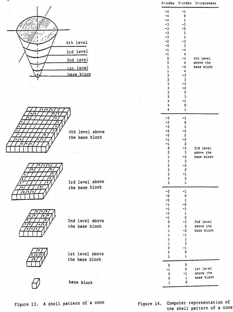
Due to both the mining sequence and the variable slope requirements for different sectors in the pit, one has to identify which waste block in the model should be removed before a particular ore block can be mined. Many iterations are generally needed to determine the overburden for an ore block. This procedure has to be repeated for all ore blocks in the mine model for numerous times in order to establish the optimal pit limit. Therefore, this procedure of overburden determination for each ore block is the main operation of the algorithm. A shell pattern (or a template) of a cone is used to perform the above iterative operation. For the sake of simplicity, 45 degree slopes at all directions and cubic blocks in the mine model are assumed in the following figures. It should be emphasized that such a template works well for variable slopes and for rectangular blocks as well.

Figure 13 shows a template which can be used to determine the overburden for an ore block. One only needs to place the template on the interested ore block and to check all the waste blocks within the template. The desired checking can be accomplished by performing vertical searches inside the template, since the lateral extent of a lower level is always contained within that of an upper level inside the template. In other words, lower levels always penetrate upper levels when the search proceeds upward. Figure 14 shows the computer representation of the template. One array is used for the relative index coordinates in X- direction and the another one is used for the relative index coordinates in Y-direction. The increments along the vertical direction can be easily applied by DO-LOOP in computer program. For a particular ore block, cone can be generated by adding the relative X and Y index coordinates and the vertical increments to the index coordinates of that ore block. Therefore, any one block within the cone can be determined by only three addition operations.

